
Index 97
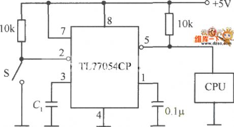
The voltage monitoring and resetting circuit composed of TL7705CP
Published:2011/6/28 20:44:00 Author:qqtang | Keyword: voltage monitoring, resetting circuit
View full Circuit Diagram | Comments | Reading(892)
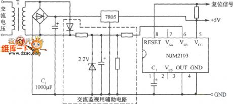
The double system monitoring circuit composed of NJM2103
Published:2011/6/28 21:37:00 Author:qqtang | Keyword: double system, monitoring circuit
View full Circuit Diagram | Comments | Reading(1122)
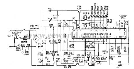
Rice cooker Circuit diagram 02
Published:2011/6/27 2:24:00 Author:zj | Keyword: Rice cooker, 01
View full Circuit Diagram | Comments | Reading(5220)
Rice cooker Circuit diagram 01
Published:2011/6/27 21:17:00 Author:zj | Keyword: Rice cooker, 01

View full Circuit Diagram | Comments | Reading(1769)
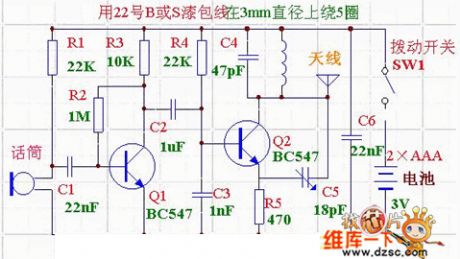
Telephone Schematic 09
Published:2011/6/27 4:11:00 Author:zj | Keyword: Telephone Schematic, 09
View full Circuit Diagram | Comments | Reading(1202)
Telephone Schematic 08
Published:2011/6/27 4:16:00 Author:zj | Keyword: Telephone Schematic, 08
View full Circuit Diagram | Comments | Reading(3657)
Telephone Schematic 07
Published:2011/6/27 4:16:00 Author:zj | Keyword: Telephone Schematic, 07
View full Circuit Diagram | Comments | Reading(1066)
Telephone Schematic 06
Published:2011/6/27 4:17:00 Author:zj | Keyword: Telephone Schematic, 06
View full Circuit Diagram | Comments | Reading(716)
Telephone Schematic 05
Published:2011/6/27 4:18:00 Author:zj | Keyword: Telephone Schematic, 05
View full Circuit Diagram | Comments | Reading(808)
Telephone Schematic 04
Published:2011/6/27 4:19:00 Author:zj | Keyword: Telephone Schematic, 04
View full Circuit Diagram | Comments | Reading(1674)
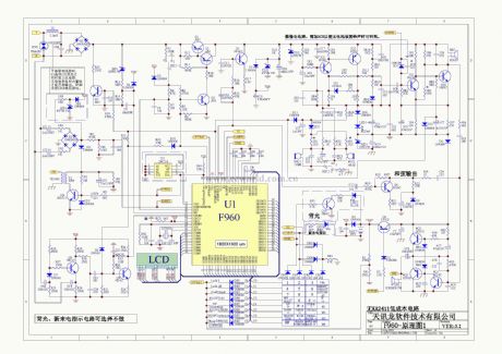
KS57C2616QFP IC Typical Application Circuit (2)
Published:2011/6/22 8:21:00 Author:Robert | Keyword: IC, Typical, Application
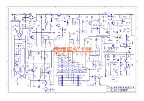
The KS57C2616QFP is a communication single-chip micro-computer IC which is mainly used as the mobile phone control microprocessor in the cordless telephone.
The KS57C2616QFP IC's internal part is made upof CPU, keys scanning pulse generating circuit, keys command coding circuit, clock oscillation circuit (main oscillation and displaying oscillation), charging detecting circuit, power control circuit, PLL circuit, screen displaying decoding driving circuit and so on.
The KS57C2616QFP IC uses 100-pin quatuor package and its typical application circuit is shown in the pictrue.
The picture shows the KS57C2616QFP IC's typical application circuit. (View)
View full Circuit Diagram | Comments | Reading(590)
The time delay alarm circuit
Published:2011/6/26 21:59:00 Author:Borg | Keyword: time delay alarm
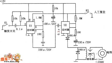
In the figure is the time delay alarm circuit. The alarm consists of 2 NE555 timers, a relay, a ring and a switch circuit, etc. When the switch K1 is closed, the first NE555 alarm is going to making sounds in 20s or so, which controls the working of the 2nd NE555. The second NE555 makes sounds for about 60s. The time delay of about 20s is for the following purposes: first, letting the thief think he is safe, so people can seize him in the basement; second, letting the owner have enough time to reset the switch.
(View)
View full Circuit Diagram | Comments | Reading(1108)
Diode light changing switch circuit
Published:2011/6/27 3:25:00 Author:TaoXi | Keyword: Diode, light changing, switch circuit
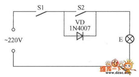
As the figure shows, when the S1 and S2 are closing, the light E lights normally; when the S1 is in the closing state, and the S2 is opening, the light E outputs the dark light; if you open S1, the light E will turn off no matter the S2 is opening or closing.
(View)
View full Circuit Diagram | Comments | Reading(642)
Teana A33-EL indoor lamp 3
Published:2011/6/22 9:55:00 Author:Nancy | Keyword: Teana, indoor lamp
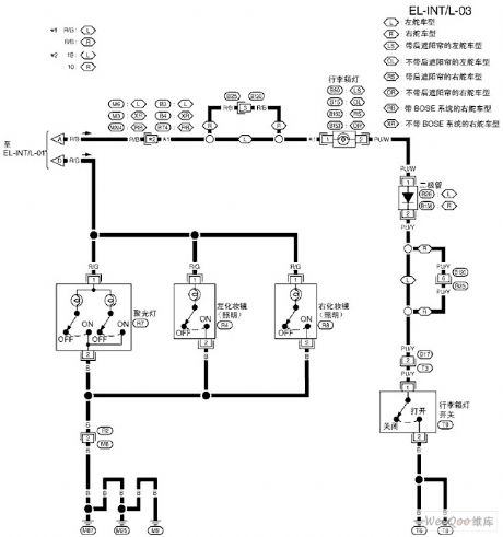
View full Circuit Diagram | Comments | Reading(566)
Teana A33-EL indoor lamp 2
Published:2011/6/22 9:54:00 Author:Nancy | Keyword: Teana, indoor lamp
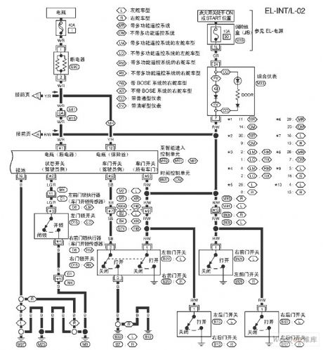
View full Circuit Diagram | Comments | Reading(557)
Teana A33-EL indoor lamp 1
Published:2011/6/22 9:52:00 Author:Nancy | Keyword: Teana, indoor lamp
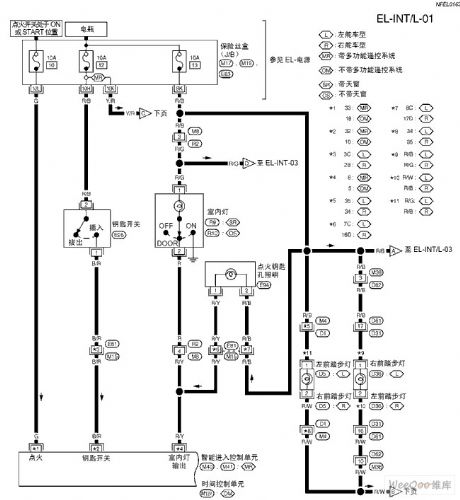
View full Circuit Diagram | Comments | Reading(508)
the interceptor circuit
Published:2011/6/25 1:58:00 Author:qqtang | Keyword: interceptor
View full Circuit Diagram | Comments | Reading(964)
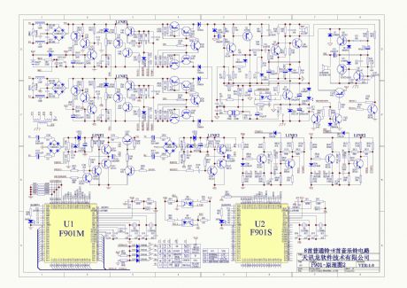
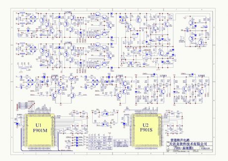
K5S7C2616B IC Typical Application Circuit
Published:2011/6/22 8:19:00 Author:Robert | Keyword: IC, Typical, Application
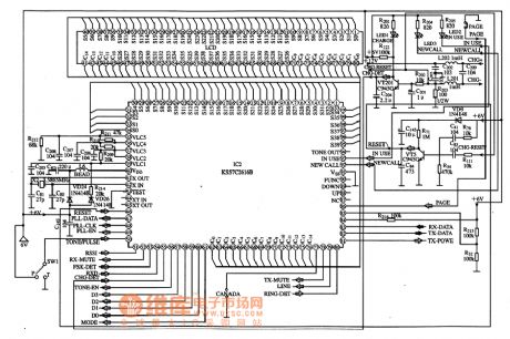
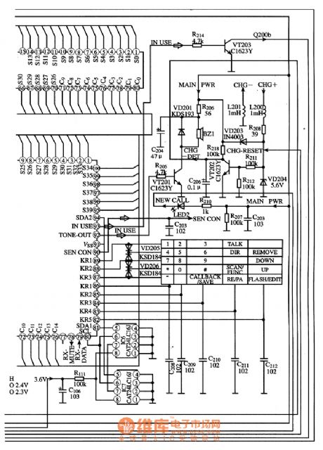
The K5S7C2616B is a communication single-chip micro-computer IC which is mainly used as the mobile phone control microprocessor in the cordless telephone.
The KS57C2616B IC's internal part is made up of CPU which is used to control many kinds of commmand signals' input and output, FSK decoding circuit, many kinds of command signals receiving and detecting circuit and resending circuit, and signal path selection circuit, system clock oscillation circuit, transmitting and receiving static double tone/pulse dialing selecting circuit, ring signal detection circuit, indicator light control, LCD liquid crystal display decoder driving circuit and so on.
The comtrol circuit's typical application circuit composed of K5S7C2616B IC is shown in the pictrue.
The picture shows the KS57C2616B IC's typical application circuit. (View)
View full Circuit Diagram | Comments | Reading(628)
Optically controlled insects trap lamp circuit diagram
Published:2011/6/18 21:00:00 Author:Lucas | Keyword: optically controlled, insects, trap lamp
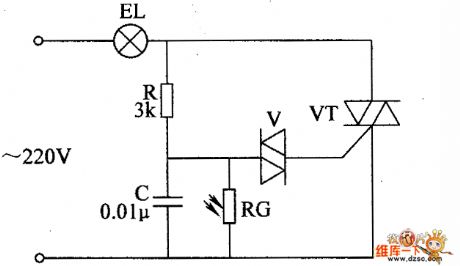
The optically controlled insects trap lamp circuit is composed of the bidirectional diode thyristor VT, two-way trigger diode V, photoresistor RC, resistor R, capacitor C, and light bulb EL, and the circuit is shown in the chart. R selects the 1W metal film resistor. RC uses MC45 series of photosensitive resistor, and it should be applied with a transparent rain cover. C selects the polyester capacitor or CBB capacitor with the voltage in 400V. V uses the DB3 or 2CTS2 two-way trigger diode. VT uses TLC336A (3A, 600V) bidirectional diode thyristor. EL uses 5 to 10 pieces of 40W, 220V incandescent bulbs conected in parallel, and the installation should add rain-proof glass shade, and lamp shade should be brushed a layer of black lacquer to enhance the effect of attracting insects.
(View)
View full Circuit Diagram | Comments | Reading(1363)
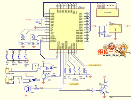
The LCD display circuit of Angel water dispenser and Samsung 57C2304
Published:2011/6/23 10:52:00 Author:qqtang | Keyword: LCD display, water dispenser
View full Circuit Diagram | Comments | Reading(1290)
| Pages:97/126 At 2081828384858687888990919293949596979899100Under 20 |
Circuit Categories
power supply circuit
Amplifier Circuit
Basic Circuit
LED and Light Circuit
Sensor Circuit
Signal Processing
Electrical Equipment Circuit
Control Circuit
Remote Control Circuit
A/D-D/A Converter Circuit
Audio Circuit
Measuring and Test Circuit
Communication Circuit
Computer-Related Circuit
555 Circuit
Automotive Circuit
Repairing Circuit