
Index 93
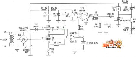
Cell phone lithium-ion battery charger circuit diagram
Published:2011/6/30 3:12:00 Author:Ecco | Keyword: Cell phone , lithium-ion, battery charger
View full Circuit Diagram | Comments | Reading(2567)
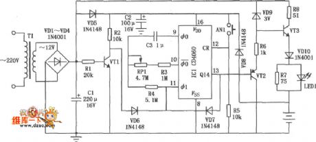
Nickel cadmium battery charger circuit diagram with timing function
Published:2011/7/1 2:17:00 Author:Ecco | Keyword: Nickel cadmium battery , charger , timing function
View full Circuit Diagram | Comments | Reading(886)
IR2156--The fluorescence lamp integrated electric ballast circuit
Published:2011/7/5 22:20:00 Author:qqtang | Keyword: fluorescence lamp, electric ballast circuit
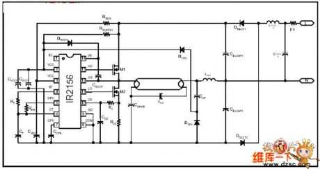
IR2156 is the high-cost, high-benefit solution of the fluorescence lamp ballast, which integrates the programmable working frequency, which can pre-heat, light lamp and keep the ballast work, the ballast and lamp fault protection.
Figure: IR2156--The fluorescence lamp integrated electric ballast circuit (View)
View full Circuit Diagram | Comments | Reading(2069)
The electric fish trap circuit (2)
Published:2011/6/23 0:46:00 Author:qqtang | Keyword: fish trap
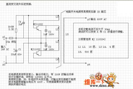
Only by changing several data can the circuit use 12V batteries. Considering the current istwo high, the power supply is designed to be 24V. The circuit should make full use of the component parameter, so that the circuit will be small-sized and efficient.
(View)
View full Circuit Diagram | Comments | Reading(2680)
The electric mosquito swatter circuit
Published:2011/6/24 8:02:00 Author:qqtang | Keyword: electric, mosquito swatter
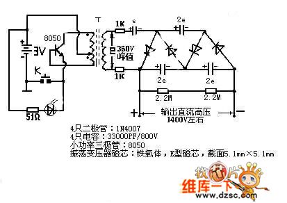
Instructions: (1) this circuit is the picture of the typical electric mosquito swatter; (2) oscillating transformer: the coil is sealed by insulated paint, so the turns are unknown, which is to be provided, the output voltage of the oscillating transformer is a AC, the peak value is 350v.(3) the oscillating transistor: as the amplifier parameters of the pipes are different, when we feel hot of the transistor while using the swatter, we can install a resistor of 100Ω or so to limit the basic electrode current, then it is cooled.(4) rectifier part
(View)
View full Circuit Diagram | Comments | Reading(11015)
Electronic pests repeller circuit diagram 1
Published:2011/6/12 22:54:00 Author:Lucas | Keyword: Electronic, pests repeller
The electronic pests repeller circuit is composed of the clock oscillator, counter, multivibrator and the audio output circuit, and the circuit is shown as the chart. Power supply circuit is composed of the power transformer T, rectifier diodes VD1 ~ VD4 and filter capacitor C1. Multivibrator is composed of the time-base IC IC1 and resistors R1, R2, capacitors C2, C3. C4 is the coupling capacitor; BL is the speaker. The AC 220V voltage bucked by T, rectified by VD1 ~ VD4 and filtered by C1 to produce 12V (Vcc) DC voltage for IC. When the multivibrator gets power and does oscillation work, the pin 3 will output 48KHz square wave, which is changed into the ultrasonic by BL radiated outward, then it can drive away near the pests.
(View)
View full Circuit Diagram | Comments | Reading(571)
Electronic pests killing lamp circuit diagram 3
Published:2011/6/12 22:56:00 Author:Lucas | Keyword: Electronic, pests killing lamp
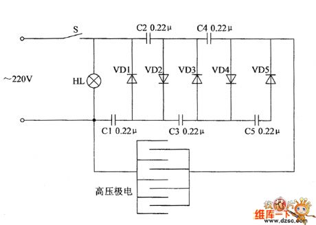
The electronic pests killing lamp circuit consists of the power switch S, trap lamp HL, high-voltage electrode, capacitors C1 ~ C5 and diodes VD1 ~ VD5, and the circuit is shown as the chart. In the circuit, C1 ~ C5 and VDI ~ VD5 form the 5 times voltage doubling rectifying circuit. Turning on the power switch s will make HL get power and light, and the AC 220V voltage which is 5 times doubled rectified by the voltage rectifier circuit can generate the DC pulse voltage with about 1400V, which is added to the high-voltage electrode. When the insects fly to trap lamp, touch or near high-voltage electrodes, they will be killed by high voltage electrodes. C1 ~ C5 select polyester or CBB capacitors with the voltage being 630Y. VD1 ~ VD5 use 1N4007 silicon rectifier diodes. S uses 3 ~ 5A, 220V AC power switch. HL uses black light or special anti-mosquito lamp.
(View)
View full Circuit Diagram | Comments | Reading(5074)
The electronic rodent repeller circuit diagram 3
Published:2011/6/30 5:35:00 Author:Lucas | Keyword: Electronic rodent repeller
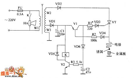
The electronic rodent repeller circuit is composed of the power transformer T, diodes VD1 ~ VD6, transistors V1 and V2, thyristor VT, relay K, alarm HA and electrode and so on, and the circuit is shown as the chart. R1 ~ R3 use of 1 / 417 carbon film resistors. C1 and C2 select aluminum electrolytic capacitors with the voltage in 16V. VD1 and VD3 ~ VD5 use 1N4007 silicon rectifier diodes; VD2 uses 1N5408 silicon rectifier diode; VD6 uses 1N4148 silicon switching diode. V1 selects 59012 silicon PNP transistor; V2 selects 59013 silicon NPN transistor. VT selects MCR100-6 thyristor. K selects 6V DC relay. HA selects the speakers or alarm bell with higher loudness . Adjusting the R1 can alter the conduction sensitivity of VT.
(View)
View full Circuit Diagram | Comments | Reading(968)
Static Elimination (the 2nd)
Published:2011/7/5 8:38:00 Author:Felicity | Keyword: Static Elimination (the 2nd)
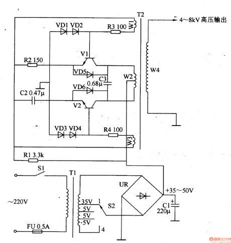
Work of the circuit
The circuit consists of power supply circuit and boost oscillation circuit. (It is showed in the picture 8-118.)
Power supply circuit consists of power switch S1, fuse FU, power transformer Tl, bridge rectifier, UR, filter capacitors Cl and voltage selector switch S2.
Boost oscillation circuit consists of resistors R1-R4, capacitors C2 and C3, diodes VDl-VD6, step-up transformer T2 and transistor Vl, V2. (View)
View full Circuit Diagram | Comments | Reading(549)
Static Elimination (the 1st)
Published:2011/7/5 8:37:00 Author:Felicity | Keyword: Static Elimination (the 1st)
Work of the circuit
The circuit consists of l2V power supply circuit, the output pulse voltage step-up circuit and LED indicator circuit. (It is showed in the picture 8-117.)
l2V power supply circuit consists of power transformer Tl, bridge rectifier, UR, filter capacitors Cl and three-terminal voltage regulator integrated circuit ICl.
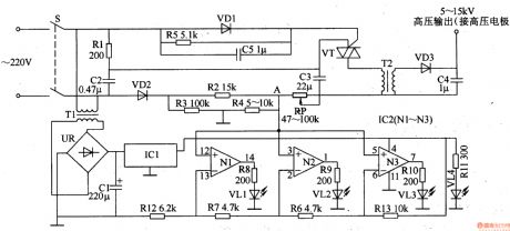
The output pulse voltage step-up circuit consists of resistors Rl-R5, capacitors C2-C5, thyristor VT, potentiometer RP, diode VDl-VD3 and step-up transformer.
LED indicator circuit consists of resistors R6-R13, light emitting diodes VLl-VL4 and operational amplifier integrated circuit IC2 (Nl-N3). (View)
View full Circuit Diagram | Comments | Reading(557)
Circuit:Car mp3 transmitter
Published:2011/6/27 1:57:00 Author:zj | Keyword: Car mp3, transmitter
View full Circuit Diagram | Comments | Reading(1586)
CXP1003S Single-Chip Micro-Computer Integrated Circuit
Published:2011/7/5 5:29:00 Author:Robert | Keyword: Single-Chip, Micro-Computer, Integrated
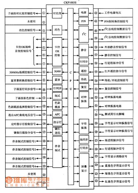
The XP1003S is a single-chip micro-computer IC which is widely used in the Konka series digital color TV sets.
1.Its functional features.
The CXP1003S IC's internal part is mainly made up of central processing unit (CPU), clock oscillation circuit, reset control circuit, key command decoding circuit, I2C bus control circuit, sound system control circuit, screen displaying character generating and processing circuit, and other some control and auxiliary function circuits. Its internal circuit diagram and pin's functions and signal flowing is shown in picture 1.
The picture 1 shows the CXP1003S IC's internal circuit diagram and pin's functions and signal flowing circuit. (View)
View full Circuit Diagram | Comments | Reading(592)
Three-Pole Gas Discharge Tube Shape Circuit
Published:2011/7/5 6:00:00 Author:Robert | Keyword: Three-Pole, Gas Discharge Tube, Shape
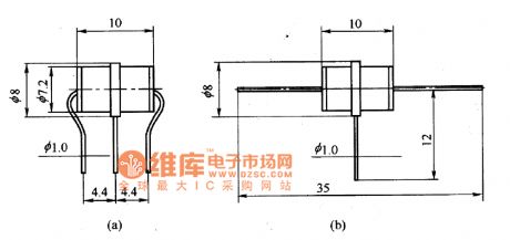
The picture shows the three-pole gas discharge tube shape circuit. (View)
View full Circuit Diagram | Comments | Reading(737)
AD651 F/V Conversion Circuit
Published:2011/7/5 6:05:00 Author:Robert | Keyword: F/V, Conversion
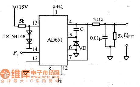
The F/V converter composed of AD651 is shown in the picture.
The picture shows the AD651 F/V conversion circuit. (View)
View full Circuit Diagram | Comments | Reading(828)
Two-Pole Gas Discharge Tube Shape Circuit
Published:2011/7/5 6:01:00 Author:Robert | Keyword: Two-Pole, Gas Discharge Tube, Shape
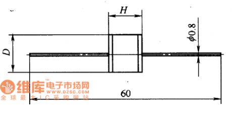
The picture shows the two-pole gas discharge tube shape circuit. (View)
View full Circuit Diagram | Comments | Reading(581)
HA174--Precise Reference Regulator IC Typical Application Circuit
Published:2011/6/20 22:12:00 Author:Robert | Keyword: Precise, Reference, Regulator, IC, Application
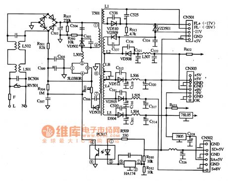
The HA117 is a precise reference regulator IC produced by Japanese Hitachi company which is widely used for sampling and amplification inmany kinds of switching circuits.
The HA174 IC's typical application circuit in switching power sampling circuit is shown in the picture.
The picture shows HA174--precise reference regulator IC typical application circuit. (View)
View full Circuit Diagram | Comments | Reading(2495)
CHNO8111 Air Conditioner Single-Chip Micro-Computer Integrated Circuit
Published:2011/6/29 23:38:00 Author:Robert | Keyword: Air Conditioner, Single-Chip, Micro-Computer, Integrated
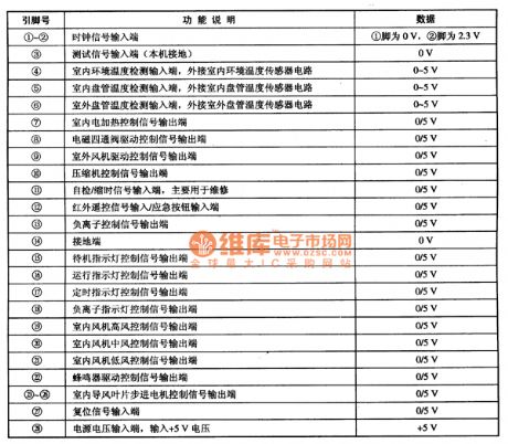
The CHNO8111 is an air conditioner single-chip micro-computer IC which is widely used in many kinds of system-control circuits in the air conditioner systems with suffix letters of DL.
The CHNO8111 IC's internal part is mainly made up of clock oscillation circuit, reset circuit, CPU, memory circuit, temperature detecting and signal processing circuit, many kinds of input/output circuits and so on.
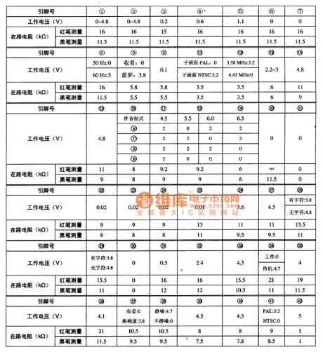
The CHNO8111 IC uses 28-pin dual inline package and its pin's function and data is listed in table 1.
The table 1 shows the pin's function and data of the CHNO8111 IC. (View)
View full Circuit Diagram | Comments | Reading(541)
IX0773CE IC Typical Application Circuit
Published:2011/7/4 0:42:00 Author:Robert | Keyword: IC, Typical, Application
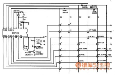
The IX0773CE is a single-chip remote-control transmitter IC produced by the SHARP company. It is widely used in the devices produced by the SHARP company such asTV sets, audio devices, players and other remote-control systems.
The IX0773CE IC has internal key scanning pulse generating circuit, remote-control command coder, clock oscillation circuit, transmitted signal buffer amplifier, testing circuit and other ancillary circuit.
The picture shows the IX0773CE IC's typical application circuit.
It is noted that the power is the energy source of the remote-control device. If there is no power supply, the remote-control device would not work normally. So it should be first to check the power of the remote-control device when the remote-control transmitter is broken. (View)
View full Circuit Diagram | Comments | Reading(763)
F117 Integrated Circuit Typical Application Circuit (2)
Published:2011/6/21 19:39:00 Author:Robert | Keyword: Integrated Circuit, Typical, Application
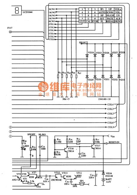
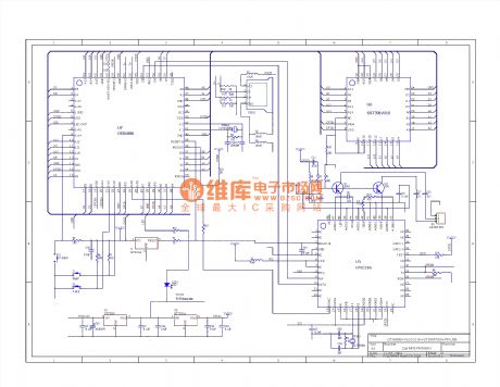
The F117 is a single-chip micro-computer integrated circuit for communication which is widely used in Fengling series full-standard caller-ID IP telephones.
The IP telephone control system typical application circuit composed of F117 integrated circuit is shown in the picture.
The picture shows the F117 integrated circuit's typical application circuit. (View)
View full Circuit Diagram | Comments | Reading(594)
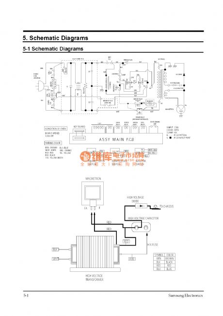
Circuit: Samsung CE959 microwave _ page _2
Published:2011/6/27 21:13:00 Author:zj | Keyword: Samsung CE959 microwave, page _2
View full Circuit Diagram | Comments | Reading(709)
| Pages:93/126 At 2081828384858687888990919293949596979899100Under 20 |
Circuit Categories
power supply circuit
Amplifier Circuit
Basic Circuit
LED and Light Circuit
Sensor Circuit
Signal Processing
Electrical Equipment Circuit
Control Circuit
Remote Control Circuit
A/D-D/A Converter Circuit
Audio Circuit
Measuring and Test Circuit
Communication Circuit
Computer-Related Circuit
555 Circuit
Automotive Circuit
Repairing Circuit