
Index 89
Electronic locust killer device 2
Published:2011/7/17 19:06:00 Author:Lucas | Keyword: Electronic locust killer
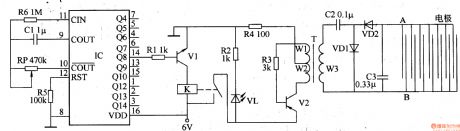
The electronic locust killer device is composed of the square wave oscillator circuit and high-voltage generator circuit, and the cirucuit is shown in Figure 3-192. Square-wave oscillator is composed of the counting divider lC and resistors R5, R6, capacitor Cl and potentiometer RP. High-voltage generator is composed of the transistors VI, V2, the relay K, resistors Rl-R4, light-emitting diode VL, step-up transformer T, capacitors C2, C3 and diodes VDl, VD2. Rl-R6 use 1/4W carbon film resistors or metal film resistors. RP uses the organic solid variable resistor. Cl selects the monolithic capacitor.
(View)
View full Circuit Diagram | Comments | Reading(2511)
Electronic locust killer device 1
Published:2011/7/17 19:13:00 Author:Lucas | Keyword: Electronic locust killer
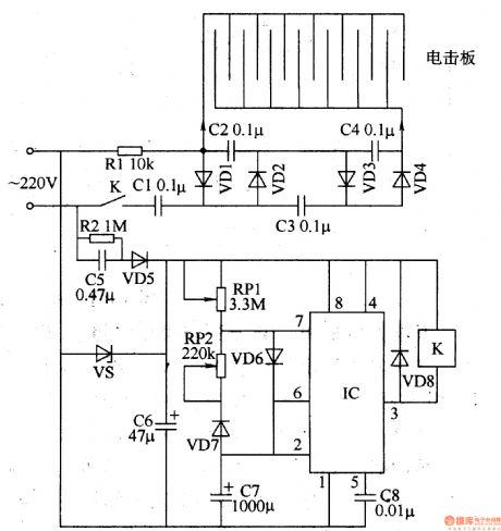
The electronic locust killer device is composed of the power supply circuit, self-excited oscillator and high-voltage generating circuit, and the cirucuit is shown in Figure 3-191. Power supply circuit consists of resistor R2, step-down capacitor C5, rectifier diode VD5, voltage regulator diode VS and filter capacitor C6. The self-excited oscillator circuit is composed of the time-base integrated circuit IC and potentiometers RPI, RP2, diodes VD6-VD8, capacitors C7, C8. High-voltage generating circuit consists of resistor Rl, doubler rectifier circuit composed of capacitors Cl-C4 and rectifier diodes VDl-VD4, and plate electrode. Rl and R2 select 1/2W metal film resistors. RPl and RP2 use the sealed miniature potentiometers or variable resistors.
(View)
View full Circuit Diagram | Comments | Reading(876)
Crystal frequency stabilization FM circuit
Published:2011/7/16 6:05:00 Author:Fiona | Keyword: frequency stabilization, FM
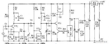
Crystal frequency stabilization FM circuit is shown as above: (View)
View full Circuit Diagram | Comments | Reading(820)
Transistor Relay Time-Delay Closing Circuit
Published:2011/7/17 0:56:00 Author:Robert | Keyword: Transistor, Relay, Time-Delay, Closing
The picture shows the transistor relay time-delay closing circuit. When it is connected to the power supply, the voltage on the 16uF capacitor would be 0V and the two triodes are all off and the relay has no action. As the 16uF capacitor charging, after some time, the voltage on it would get to high voltage level and the two triodes are all turned on and the relay would be closed after the delay time. The delay time could be 60s. The length of delay time can be adjusted by the 10MΩ resistor. (View)
View full Circuit Diagram | Comments | Reading(772)
-500~0V High-Power Operational Amplifier Circuit
Published:2011/7/17 1:34:00 Author:Robert | Keyword: High-Power, Operational Amplifier
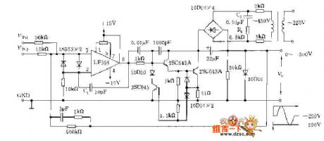
The picture shows the -500~0V high-power operational amplifier circuit. (View)
View full Circuit Diagram | Comments | Reading(617)
Single-Phase Electronic Prepaid Watt-Hour Meter Design Circuit
Published:2011/7/17 7:47:00 Author:Robert | Keyword: Single-Phase, Electronic, Prepaid, Watt-Hour Meter, Design
The picture shows the single-phase electronic prepaid watt-hour meter design circuit. (View)
View full Circuit Diagram | Comments | Reading(1845)
RTC-4553 Pin And Its Peripheral Circuit
Published:2011/7/16 21:27:00 Author:Robert | Keyword: Pin, Peripheral
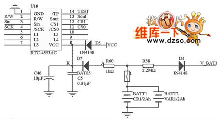
The picture shows the RTC-4553 pin and its peripheral circuit. (View)
View full Circuit Diagram | Comments | Reading(772)
Over-Voltage Alarming Circuit By Using LT1073
Published:2011/7/16 9:13:00 Author:Robert | Keyword: Over-Voltage, Alarming
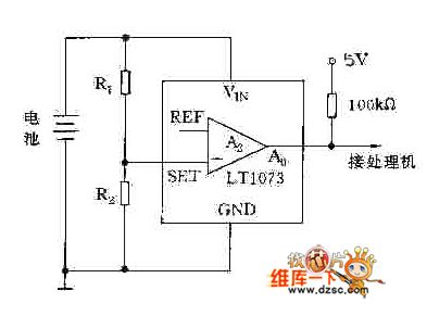
The picture shows the over-voltage alarming circuit by using LT1073. (View)
View full Circuit Diagram | Comments | Reading(561)
SA9904 Pin And Peripheral Circuit
Published:2011/7/16 9:03:00 Author:Robert | Keyword: Pin, Peripheral
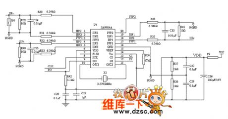
The picture shows the SA9904 pin and peripheral circuit. (View)
View full Circuit Diagram | Comments | Reading(849)
Communication Serial Port Multiplexing Circuit
Published:2011/7/16 21:26:00 Author:Robert | Keyword: Communication, Serial, Port, Multiplexing

The picture shows the communication serial port multiplexing circuit. (View)
View full Circuit Diagram | Comments | Reading(809)
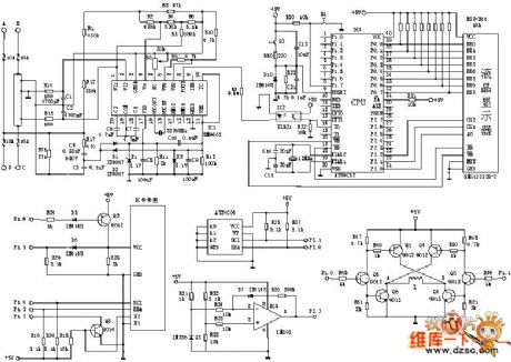
Multifunctional Energy Meter Overall Structure Circuit
Published:2011/7/17 7:10:00 Author:Robert | Keyword: Multifunctional, Energy, Meter, Overall, Structure
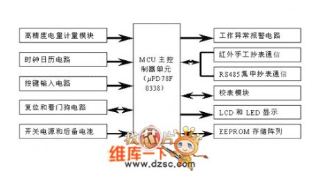
The picture shows the multifunctional energy meter overall structure circuit. (View)
View full Circuit Diagram | Comments | Reading(525)
500 Type Multimeter Circuit Principle Instrumetation Circuit
Published:2011/7/16 10:15:00 Author:Robert | Keyword: Multimeter, Principle, Instrumetation
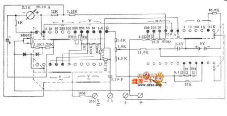
The picture shows the 500 type multimeter circuit principle instrumetation circuit. (View)
View full Circuit Diagram | Comments | Reading(1550)
Power Rectifier Protector Circuit
Published:2011/7/17 7:15:00 Author:Robert | Keyword: Power, Rectifier, Protector
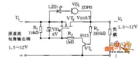
The picture shows the power rectifier protector circuit. (View)
View full Circuit Diagram | Comments | Reading(552)
I/O Interface And Static Switch Driving Circuit
Published:2011/7/17 8:13:00 Author:Robert | Keyword: I/O, Interface, Static, Switch, Driving
The picture shows the I/O interface and static switch driving circuit. (View)
View full Circuit Diagram | Comments | Reading(525)
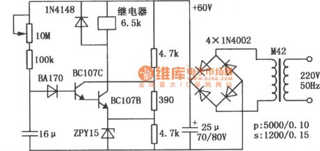
Electronic fly disinfestation browser
Published:2011/5/12 2:12:00 Author:Ecco | Keyword: Electronic , fly disinfestation browser
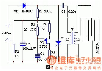
This electronic fly disinfestation browser is simple and easy to make, it is used to wipe out all flies which fly to the power grid of the device.
The circuit is shown in Figure 1. The whole device is supplied by the 220V electric supply after being rectified. R3, R4, R5, C1 and double-base diode form a relaxation oscillator, the output pulse signal is used to control the SCR's turning on and off. When SCR is in the off state, electric supply VD is rectified and charges for C3 by equivalent resistor R6 and L1. When VS is triggered and turned, C3 discharges rapidly by SCR and the equivalent resistor of L1. When the discharging current is over zero, the SCR cuts off automatically. This repeats the cycle, the secondary stage L2 of transformer gets a high pulse voltage, the voltage is applied to the power grid composed of many equidistant electrical wire, power grid sets bait to attractflies, and when they touch the grid, they will be electrocuted and then drop from the space, that realize the effect of automatically disinfestation. (View)
View full Circuit Diagram | Comments | Reading(658)
Headache electronic physical therapy device circuit diagram
Published:2011/5/11 4:20:00 Author:Ecco | Keyword: electronic physical therapy device
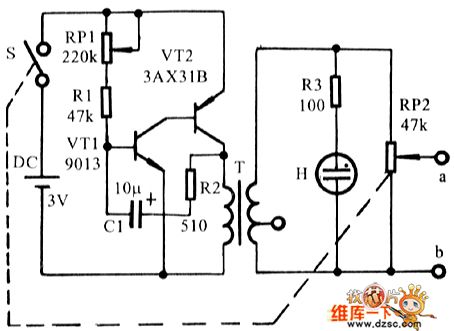
Physical therapy device circuit diagram is shown as the chart. The complementary type square-wave generator is composed of transistor VT1, VT2, and space multiplier is boosted by transformer T, then output by at a and b ports by BP2. H stands for NH - 416 type neon bulb. When the circuitry works, it will shine, indicate working status. RP1 is a type of frequency adjust potentiometer which can adjust the oscillation frequency, and we can see it from the shine of H. RP2 is a type of output strength adjust potentiometer(with switch). T could use output transformer in common transistor radios, the original 8 Ω terminal connects connentor VT2. VT1 requires that β≥100, and VT2 requires β≥50.
It needs a pair of pars of multimeter when using it, and one connects to port a of the machine, and the other one connects to port b. When paients have a headache, they could handle a par, and the other one connects to temple or frontal headache site, then open the power supply. Firstly, RP1 is put in the middle position, and make and gradually increase of RP2 until the skin contact par has the sense of acupuncture or movement. The strength of first physical shoulds not be too strong. It can be make paients feel good by adjusting PR1 to change the frequency. General physical therapy should be proper in 2 ~ 5 minutes, headache instantly disappears. If invalid, it need to be changed the frequency and appropriately increase strength, if we physiotherapy 5 minutes again, still have a headache, we will not have to try, and that explains this physical therapy device is not suitable for you.
(View)
View full Circuit Diagram | Comments | Reading(2269)
Electric Water Heater Circuit 03
Published:2011/6/30 22:15:00 Author:zj | Keyword: Electric Water Heater, 03
View full Circuit Diagram | Comments | Reading(660)
TDA4863A Circuit
Published:2011/7/13 7:53:00 Author:Robert | Keyword: Circuit
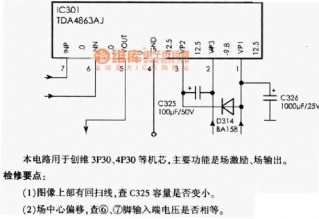
The picture shows the TDA4863A circuit.
This circuit is used in the Chuangwei 3P30, 4P30 etc. cassette mechanism with main function of field excitation, field output.
Maintenance points: (1)Theflyback lines above the picture can be used to check if the C325's capacity is lower or not. (2)For field center offset it would check if the pin 6 and pin 7's input port voltage are equal. (View)
View full Circuit Diagram | Comments | Reading(4942)
MF92 Multimeter Circuit
Published:2011/7/13 7:57:00 Author:Robert | Keyword: Multimeter
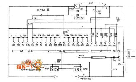
The picture shows the MF92 multimeter circuit. (View)
View full Circuit Diagram | Comments | Reading(742)
MF93 Multimeter Circuit
Published:2011/7/13 7:58:00 Author:Robert | Keyword: Multimeter
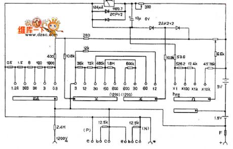
The MF93 multimeter circuit. (View)
View full Circuit Diagram | Comments | Reading(649)
| Pages:89/126 At 2081828384858687888990919293949596979899100Under 20 |
Circuit Categories
power supply circuit
Amplifier Circuit
Basic Circuit
LED and Light Circuit
Sensor Circuit
Signal Processing
Electrical Equipment Circuit
Control Circuit
Remote Control Circuit
A/D-D/A Converter Circuit
Audio Circuit
Measuring and Test Circuit
Communication Circuit
Computer-Related Circuit
555 Circuit
Automotive Circuit
Repairing Circuit