
Index 99
CH0403-5H61 Single-Chip Computer Integrated Circuit
Published:2011/6/14 23:33:00 Author:Robert | Keyword: Single-Chip, Computer, Integrated
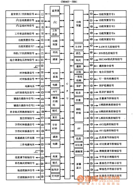
The CH0403-5H61 is a single-chip micro-computer integrated circuit which is widely used in Changhong etc. large screen digital color TVs. The CH0403-5H61 has internal central processing unit (CPU), clock oscillation circuit, reset control circuit, keys command decoder circuit, I(2)C bus control circuit, remote control telecommand signal processing circuit, screen displaying and character generation and processing circuit and other some control or secondary function circuit. Its internal circuit diagram and pin function and signal flow is shown in picture 1.
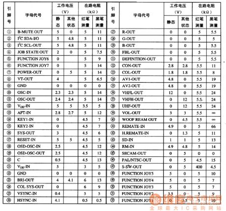
The CH0403-5H61 integrated circuit uses 52 feet double-row package, its pin function is shown in picture 1 and its pin's letter code and data is shown in table 1. (View)
View full Circuit Diagram | Comments | Reading(568)
Fuse Installation Method Circuit
Published:2011/6/14 23:34:00 Author:Robert | Keyword: Fuse, Installation Method
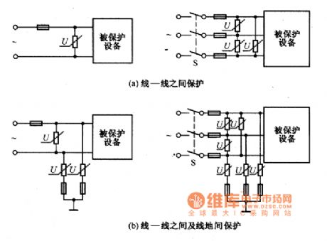
By taking measures to protect the piezoresistor it can avoid the external uncertain factor which can get damage to the piezoresistor and device. If it's going to install a fuse in the circuit, the installation method is shown in the picture.
(a)Protection between wire to wire. (b)Protection between wire to wire and wire to ground. (View)
View full Circuit Diagram | Comments | Reading(546)
The Otis 300vf elevator mainstream circuit
Published:2011/6/20 10:41:00 Author:Seven | Keyword: elevator, mainstream circuit

The Otis 300vf elevator mainstream circuit is shown in the following circuit.
(View)
View full Circuit Diagram | Comments | Reading(3368)
HT6308 Integrated Circuit Typical Application Circuit
Published:2011/6/15 0:34:00 Author:Robert | Keyword: Integrated Circuit, Typical, Application
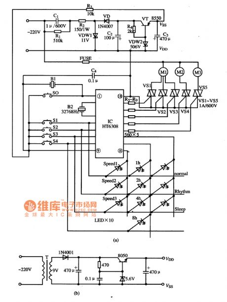
The Ht6308 is a fan single-chip micro-computer IC which widely used in many kinds of fan program control circuits.
The fan control system typical application circuit composed of HT6308 IC is shown in the picture.
The picture shows the HT6308 IC's typical application circuit. (View)
View full Circuit Diagram | Comments | Reading(645)
HM9110E Integrated Circuit Typical Application Circuit
Published:2011/6/14 23:18:00 Author:Robert | Keyword: Integrated Circuit, Typical, Application
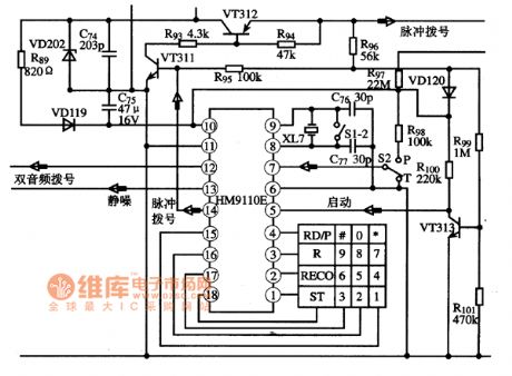
The HM9110E is a communication single-chip micro-computer integrated circuit produced by the Hitachi company which is widely used for dial-up and control circuit in communications equipments.
The dial and control typical application circuit composed of HM9110E integrated circuit is shown in the picture.
The picture shows the HM9110E integrated circuit's typical application circuit. (View)
View full Circuit Diagram | Comments | Reading(762)
HIC1026A Integrated Circuit Typical Application Circuit
Published:2011/6/14 23:19:00 Author:Robert | Keyword: Integrated Circuit, Typical, Application
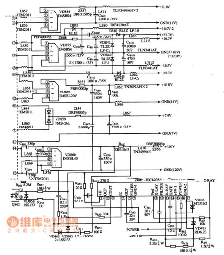
The HICl026A is a multi-function power integrated circuit produced by the Hitachi company which is widely used in Toshiba AG series rear-projection color TV.The protection module typical application circuit composed of HIC1026A integrated circuit is shown in the picture (this picture is TV original picture and it has not fixed the graphic symbols which are not meeting the standard).
The picture shows the HICl026A integrated circuit's typical application circuit. (View)
View full Circuit Diagram | Comments | Reading(871)
HIC1026A Integrated Circuit Internal Principle Circuit
Published:2011/6/14 23:20:00 Author:Robert | Keyword: Integrated Circuit, Internal, Principle
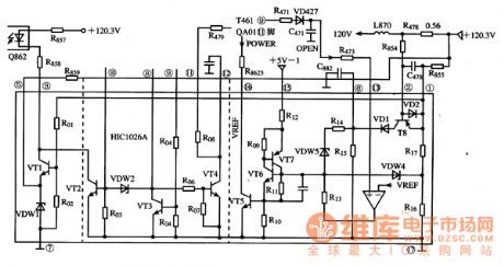
The HICl026A is a multi-function power integrated circuit produced by the Hitachi company which is widely used in Toshiba AG series rear-projection color TV.
The picture shows the HICl026A integrated circuit's internal principle circuit.
(View)
View full Circuit Diagram | Comments | Reading(699)
HA31002P Integrated Circuit Typical Application Circuit
Published:2011/6/14 23:20:00 Author:Robert | Keyword: Integrated Circuit, Typical, Application
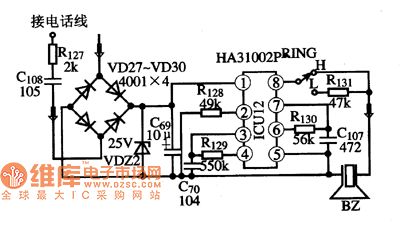
The HA31002P is aelectronic bell integrated circuit produced by Hitachi company which is widely used in communication equipments such as cordless phones andcorded phones and so on.
The picture shows the HA31002P integrated circuit's typical application circuit. (View)
View full Circuit Diagram | Comments | Reading(2058)
The electronic rodent repeller circuit diagram 1
Published:2011/6/14 20:30:00 Author:Lucas | Keyword: Electronic rodent repeller
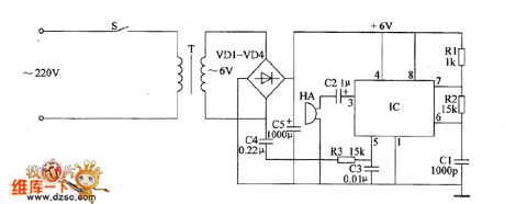
The electronic rodent repeller circuit is composed of the power circuit, oscillator and piezoelectric buzzer HA, and the circuit is shown as the chart. Power circuit is composed of the power switch S, power transformer T, rectifier diodes VD1 ~ VD4 and filter capacitor C5 and so on. The oscillator is composed of time-base integrated circuit IC, resistors R1 ~ R3 and capacitors C1 ~ C3 and other components. R1 ~ R3 use 1/4W or 1/8W carbon film resistors. C1 chooses high-frequency ceramic capacitor; C2 and C5 select aluminium electrolytic capacitors with the voltage in 16V; C3 and C4 use polyester capacitors or monolithic capacitors. VD1 ~ VD4 select 1 N4007 or 1N4001 silicon rectifier diodes. IC uses NE555 time-base integrated circuit. S uses a small button self-locking switch. HA uses piezoelectric buzzer.
(View)
View full Circuit Diagram | Comments | Reading(1161)
Electronic pests killing lamp circuit diagram 8
Published:2011/6/13 5:39:00 Author:Lucas | Keyword: Electronic , pests killing lamp
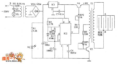
The electronic pests killing lamp circuit is composed of the power supply circuit, pulse oscillator and high-voltage generator circuit, and the circuit is shown as the chart. Power supply circuit is composed of the power switch S, fuse FU, power transformer T1, rectifier diodes VD1 ~ VD4, filter capacitors C1, C3, three-terminal voltage regulator integrated circuit IC1, limiting resistor RI and power indicator light-emitting diode VL. Pulse oscillator is composed of the time-base integrated circuit IC2, resistors R2, R3, potentiometer RP1 and capacitors C2, C4. High-voltage generator consists of transistors V1, V2, potentiometers RP2, RP3, resistors R4, R5, pulse transformer and high-voltage grid ( high voltage electrodes A, B). EL is the trapping light; C5 is the buck capacitor.
(View)
View full Circuit Diagram | Comments | Reading(1566)
Electronic pests killing lamp circuit diagram 7
Published:2011/6/13 5:47:00 Author:Lucas | Keyword: Electronic, pests killing lamp
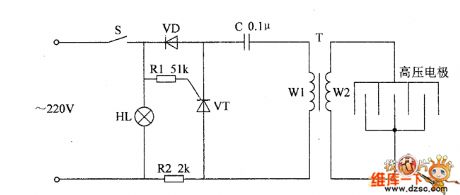
The electronic pests killing lamp circuit is composed of the power switch S, trapping lamp HL, diode VD, thyristor VT, resistors R1, R2, capacitor C, pulse high-voltage transformer T and high voltage electrodes, and the circuit is shown as the chart. R1 selects 1/4W metal film resistor or carbon film resistor; R2 uses 3W wire-wound resistor. C uses the CBB polypropylene capacitor with the voltage in 630V. VD selects 1N4007 silicon rectifier diode. VT selects MCR100-8 thyristor. T uses the black and white TV discreting line output transformer restructuring, W1 winding uses Φ0.35mm high strength varnished wire with about 30 to 50 turns; W2 winding uses FBT. HL chooses 2 ~ 5W UV lamp or black light. S selects 5A, 250V AC power switch.
(View)
View full Circuit Diagram | Comments | Reading(922)
Electronic pests killing lamp circuit diagram 6
Published:2011/6/13 5:53:00 Author:Lucas | Keyword: Electronic, pests killing lamp
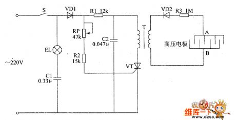
The electronic pests killing lamp circuit is composed of the lighting circuit and high voltage generator, and the circuit is shown as the chart. High-voltage generator circuit is composed of the diodes VD1, VD2, thyristor VT, resistors R1 ~ R3, potentiometer RP, pulse transformer T and the high voltage grid ( high voltage electrodes A, B). Adjusting the resistance of RP can change the sensitivity of VT conduction to change the level of DC high voltage of grid. R1 ~ R3 select 2W metal film resistors. RP selects the the synthetic membrane potentiometer with switch (S). C1, C2 use the CBB capacitors or polyester capacitors with the voltage in 630V. VD1 selects 1N4007 silicon rectifier diode; VD2 uses ZDGL/15kV high voltage silicon rectifier stack.
(View)
View full Circuit Diagram | Comments | Reading(1668)
Agricultural automatical water feeder circuit diagarm 12
Published:2011/6/14 5:41:00 Author:Lucas | Keyword: Agricultural, automatical , water feeder

The agricultural automatical water feeder circuit is composed of the power supply circuit, water level detection circuit and control implementation circuit,and the circuit is shown as the chart 1. Power supply circuit is composed of the power transformer T, rectifier diodes VD1 ~ VD4 and filter capacitor C1. Water level detection circuit is composed of the high water level electrode A, low water level electrode B and the main electrode C. Control implementation circuit is composed of the IC and relay K, AC contactor KM and other components. AC 220V voltage is bucked by T, rectified by VD1 ~ VD4 and filtered by C1 to provide 10V DC voltage for IC. RI and R2 select 1/4W carbon film resistors. C1 chooses the aluminum electrolytic capacitor with the voltage in 16V; C2 uses the polyester capacitor or monolithic capacitor.
(View)
View full Circuit Diagram | Comments | Reading(915)
Bell of the Bicycle (the 4th)
Published:2011/6/6 5:12:00 Author:Felicity | Keyword: Bell of the Bicycle (the 4th)
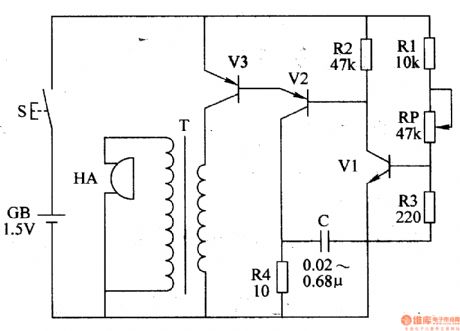
Work of the circuit
The circuit consists of LPO amplifying outputting circuit (transistor V1,V2, potentiometer RP, resistor R1-R4 and capacitor C) and power circuit (It is showed in picture 7-170.).
Press control button S and LPO begins to work. The signalwhich isproduced by LPOdrives HA to make sound “tick” after being amplified by V3.
Change the value of RP or C to change the volume. (View)
View full Circuit Diagram | Comments | Reading(686)
Bell of the Bicycle (the 3rd)
Published:2011/6/6 5:17:00 Author:Felicity | Keyword: Bell of the Bicycle (the 3rd)
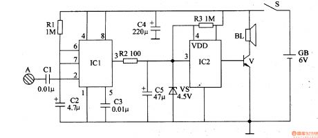
Work of the circuit
The circuit consists of audio frequency oscillator, LFO and voice outputting circuit (It is showed in picture 7-169.).
When you press button S and LFO starts to work and VL shines. In the meantime audio frequency oscillator is modulated. The modulating pulse signal which is outputted from IC’s pin 3 drives BL to make the sound “honk honk”. (View)
View full Circuit Diagram | Comments | Reading(583)
Bell of the Bicycle (the 1st)
Published:2011/6/6 5:27:00 Author:Felicity | Keyword: Bell of the Bicycle (the 1st)
Work of the circuit
The circuit consists of monostable trigger and voice circuit. (It is showed in picture 7-167.).
When you turn on the power switch Sthemonostable trigger is in the stable condition. Loudspeaker BL makes no sound.
When our hand touches pole A the body inducted signal is supplied to IC1’s pin 2 through C1. In this situation loudspeaker BL makes sound. (View)
View full Circuit Diagram | Comments | Reading(643)
electric power blender circuit diagram
Published:2011/5/11 1:46:00 Author: | Keyword: electric, blender
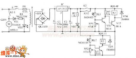
Electric power blender is usually used in industrial and mining enterprises.Because the mixed material produce scent and powder,workers are not suitable to contact too close.A light controlled electric blender(or other circuit )circuitshown in the figure, uses common flashlight beam as remote control instruction, which can control blender operation in 10m.This circuit can be enclosed in a plastic box,which is used very convenient.
components and parts:IC selects AN7812 three-terminal voltage IC.VT1~VT3 uses 9014 dynatron.RL1 and RL2 uses MG44-03 type plastic resin encapsulated photosensitive resistant,or selects other common photosensitive resistant (light 5KΩ,dark ≥1MΩ) instead.VD2,VD3 are LEDs.T is 8W~10W power transformer.Other selected components and parts are shown as figure.
(View)
View full Circuit Diagram | Comments | Reading(6799)
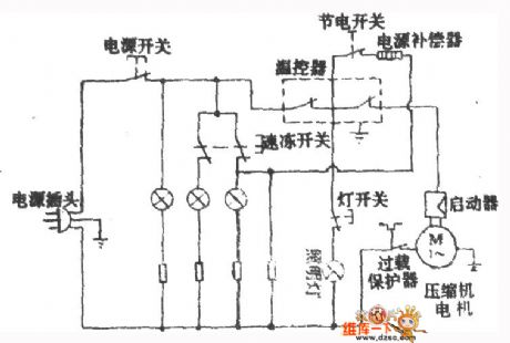
xinfei BCD-245 fridge circuit diagram
Published:2011/5/11 1:45:00 Author: | Keyword: fridge, circuit
View full Circuit Diagram | Comments | Reading(605)
50MH2 Photoelectric Demodulation Circuit
Published:2011/5/26 9:30:00 Author:Robert | Keyword: 50MH2, Photoelectric, Demodulation
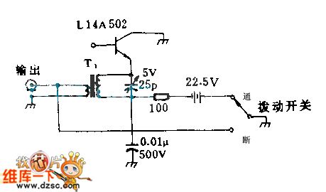
The parallel tuned method can be used in the single GE type photodiode circuit in the picture. When the parallel photodiodes have five, it is required to use the series tuned method. If the tuned capacitance uses its 0PF, the frequency response could be about 00MHz. T1's primary stage is 2 laps and its secondary stage is 7 laps, which wind around the high-frequency plastic core.
(View)
View full Circuit Diagram | Comments | Reading(591)
Infrared Reflective Driving Distance Reminder Circuit
Published:2011/5/17 5:40:00 Author:Robert | Keyword: Infrared Reflective, Driving Distance, Reminder
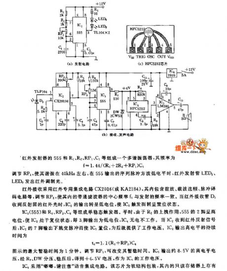
The picture (a) is transmitter circuit. The picture (c) is HFC5212 chip. The picture (b) is receiver and sound circuit.
The infrared transmitter's 555 and R1, R2, RP1, C1 etc. make up a multivibrator with frequency of f=1.44/(R1+2R2+RP1)C1.
By adjusting RP1 to make the oscillation at about 40kHz, the infrared launch tube LED1, LED2 would have infrared modulated light when the sequence pulses square wave from 555 is low voltage level.
The infrared receiver uses the infrared special integrated circuit CX2016 (or KA2184) which has front amplifier, carrier frequency selection, pulse decoder circuit and so on. By adjusting RP2 to make its internal bandpass filter's central frequency be the same with transmitter frequency. When the infrared receiver tube D3 has received the reflected infrared light, IC2's output voltage becomes low voltage level to trigger the IC3 to be set mode.
(View)
View full Circuit Diagram | Comments | Reading(742)
| Pages:99/126 At 2081828384858687888990919293949596979899100Under 20 |
Circuit Categories
power supply circuit
Amplifier Circuit
Basic Circuit
LED and Light Circuit
Sensor Circuit
Signal Processing
Electrical Equipment Circuit
Control Circuit
Remote Control Circuit
A/D-D/A Converter Circuit
Audio Circuit
Measuring and Test Circuit
Communication Circuit
Computer-Related Circuit
555 Circuit
Automotive Circuit
Repairing Circuit