
Index 96
IRT1260 IC Typical Application Circuit
Published:2011/6/27 9:08:00 Author:Robert | Keyword: IC, Typical, Application
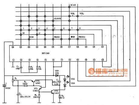
The IKT1260 is a single-chip remote-control transmitter IC which is widely used in many kinds of remote-control systems such as TV sets, audio equipments, players, air conditioners and so on.
The infrared remote-control transmitter typical application circuit composed of IRT1260 is shown in the picture.
The picture shows the IRT1260 IC's typical application circuit. (View)
View full Circuit Diagram | Comments | Reading(2172)
JFCPU IC Typical Application Circuit
Published:2011/6/27 9:32:00 Author:Robert | Keyword: IC, Typical, Application
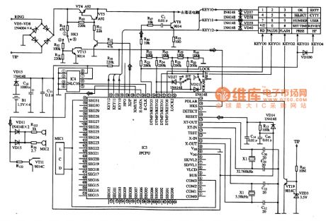
The JFCPU is a single-chip micro-computer IC for communication which is widely used in Guowei series computer billing telephone.
The JFCPU IC's internal part is mainly made up of clock oscillation circuit, double-tone dialing circuit, E2PROM memory, key bit pulse generating circuit, key command coding circuit, reset control circuit, starting control circuit, LCD display decoding driving circuit and so on.
The control system typical application circuit composed of JFCPU IC is shown in picture.
The picture shows the JFCPU IC's typical application circuit. (View)
View full Circuit Diagram | Comments | Reading(758)
CH52011 System Control Single-Chip Micro-Computer Integrated Circuit
Published:2011/6/24 7:36:00 Author:Robert | Keyword: System, Control, Single-Chip, Micro-Computer, Integrated

The CH52011 is a system control single-chip micro-computer IC which is widely used in the Changhong series of VCD players.
1.Its function features.
The CH52011 IC is mainly used to control the servo circuit, digital signal processing circuit, decoding circuit, the displaying part of front panel and audio signal D/A conversion and the input part's work.
2.Its pin's function and data.
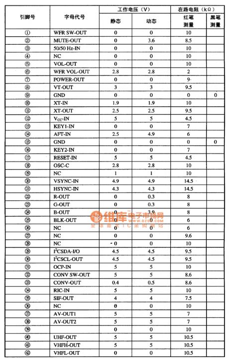
The CH52011 IC uses 64-pin dual inline package and its pin's function and data is listed in table 1.
The table 1 shows CH52011 IC's pin's function and data. (View)
View full Circuit Diagram | Comments | Reading(559)
HT6337A IC Typical Application Circuit
Published:2011/6/24 7:15:00 Author:Robert | Keyword: IC, Typical, Application
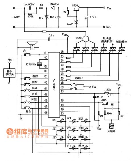
The HT6337A is a fan single-chip micro-computer IC which is widely used in many brands of remote-control fans.
The fan remote-control system typical application circuit composed of HT6337A is shown in the picture.
The picture shows the HT6337A IC's typical application circuit. (View)
View full Circuit Diagram | Comments | Reading(912)
KA2418 IC Typical Application Circuit
Published:2011/6/22 10:06:00 Author:Robert | Keyword: IC, Typical, Application
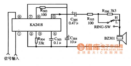
The KA2418 is a special ringing IC produced by Samsung company. It is used as ringing circuit in many kinds of communication devices, such as the application in cordless telephones and corded telephones and so on.
The ringing typical application circuit composed of KA2418 IC is shown in the picture.
The picture shows the KA2418 IC typical application circuit.
It should be noted that the pin 1 and pin 8 and pin 5 are the two key detecting points. If the pin 5 has no about 12V voltage output, it is more likely that the IC is damaged. (View)
View full Circuit Diagram | Comments | Reading(4226)
KA3524 IC Internal Diagram Circuit And Pin Function
Published:2011/6/25 21:24:00 Author:Robert | Keyword: IC, Internal, Diagram, Pin

The KA3524 is a PWM switching power IC produced by the Samsung company which has many applications in the players, air conditioner control systems, computers and monitors.
The KA3524 IC has internal referenced voltage regulator, sawtooth oscillator, error amplifier, current limit circuit, comparator, flip-flops, closing control circuit and so on. Its internal diagram circuit and pin function is shown in the picture.
The picture shows the KA3524 IC's internal diagram circuit and pin function. (View)
View full Circuit Diagram | Comments | Reading(2288)
CHO4T1218 Single-Chip Micro-Computer Integrated Circuit
Published:2011/6/14 23:34:00 Author:Robert | Keyword: Single-Chip, Micro-Computer, Integrated
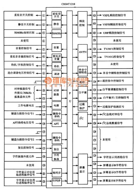
The CHO4T1218 is a single-chip micro-computer integrated circuit which is widely used in Changhong, Toshiba etc. digital color TV. The CHO4T1218 integrated circuit has internal central processing unit (CPU), clock oscillation circuit, reset control circuit, key commanding signal decoding circuit, I(2)C bus control circuit, remote control telecommand signal processing circuit, screen displaying and character generating and processing circuit, standby power and starting power control circuit, TV/AV control circuit, subwoofer control circuit, white balance control circuit and some other control or secondary function circuit. Its internal circuit disgram and pin functions and signal flow is shown in picture 1. (View)
View full Circuit Diagram | Comments | Reading(589)
Nickel cadmium battery automatical charger, discharger circuit diagram
Published:2011/6/28 2:31:00 Author:Ecco | Keyword: Nickel cadmium , battery , automatical, charger, discharger
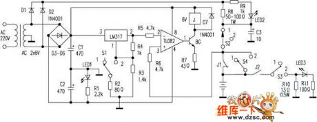
This circuit can use two nickel-cadmium batteries, when it is charged to 3V or discharge to 1-34V, it automatically disconnect the charging or discharging circuit to effectively prevent the overcharge or over discharge. The voltage rectified by D1, D2 to supply the battery, and the voltage rectified by D3 ~ D6 to supply voltage comparing and controlling circuit. TL082 constitutes a comparison circuit, and the pin 2 of LM317 provides a constant output voltage as a reference point, and the voltage of pin 3 is from the battery. Controlling the relay can control charge or discharge circuit.
(View)
View full Circuit Diagram | Comments | Reading(1412)
Universal infrared remote control power outlet circuit diagram
Published:2011/6/28 3:02:00 Author:Ecco | Keyword: Universal, infrared , remote control , power outlet

Outlet circuit is shown in Figure 1. The circuit uses a receiver, amplification, demodulation integrated infrared receiver, and the relay trigger drive circuit uses one dual D flip-flop MC14013, and the circuit uses only one way, which is connected into a bi-stable form, and D is connected to Q, R, S are grounded. R3, C2 RC network connected to the R side has the power-on reset function to ensure the socket is in off state when the circuit gets power after power cut. Figure 2 shows the PCB map.
(View)
View full Circuit Diagram | Comments | Reading(2280)
The circuit of a watchdog
Published:2011/6/27 22:47:00 Author:Borg | Keyword: watchdog
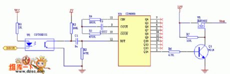
See as the above figure: when the circuit is working, just send CD4060 the reset pulse timely, the Q1 will be blocked, so the NMOS pipe under control is conducting and provides with power for the processor circuit. The virtue of the circuit is that the timing-span is long, which can be several minutes, so it can offer enough time to the systems whose reset time is long. With the pulse feeding the watchdog, when the power is getting through, the counter is offered with a reset pulse by R2, C1 and R3, so Vout is made sure to have output. (View)
View full Circuit Diagram | Comments | Reading(753)
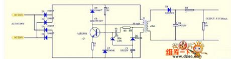
MP3 charger circuit diagram
Published:2011/6/28 2:56:00 Author:Ecco | Keyword: MP3 charger
View full Circuit Diagram | Comments | Reading(667)
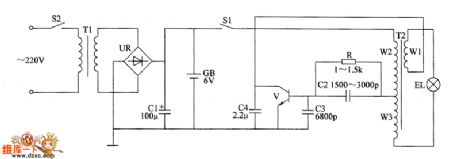
Plastic bag sealing machine circuit diagram 3
Published:2011/6/14 2:57:00 Author:Lucas | Keyword: Plastic bag , sealing machine

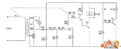
The plastic bag sealing machine circuit is composed of power supply circuit, heating control circuit and indicating circuit, and the circuit is shown as the chart. Power supply circuit is composed of the power switch S1, power transformer T, rectifier diode VD1, filter capacitor C1, resistor R1 and the current limiting voltage regulator diode VS. Heating control circuit consists of resistors R2 ~ R4, potentiometer RP, capacitor C2, transistors V1, V2, relay K, diode VD2, control switch S2, heater EH. Indicating circuit is composed of the power light HL1, working status indicator HL2, resistor R5, capacitor C3, transistor V3, and the normally open contact K2 of K. R1 ~ R5 use 1/4W carbon film resistors or metal film resistors.
(View)
View full Circuit Diagram | Comments | Reading(5602)
Electronic fishing shrimp machine circuit diagram 2
Published:2011/6/14 4:00:00 Author:Lucas | Keyword: Electronic , fishing shrimp machine
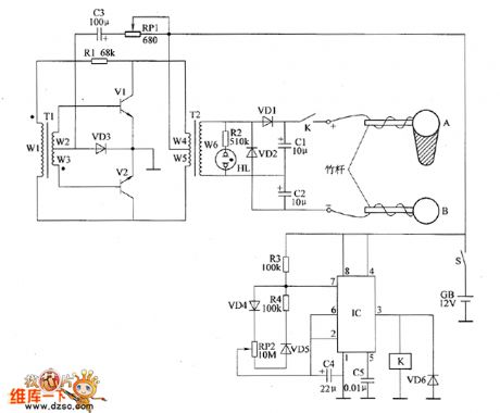
The ectronic fishing shrimp machine circuit is composed of the astable oscillator, inverter circuit, high voltage output circuit, and the circuit is shown as the figure 20. Astable oscillator circuit is composed of the time-base integrated circuit IC, resistors R3, R4, potentiometer RP2, diodes VD4, VD5 and capacitors C4, C5. Inverter circuit is composed of the transistors V1, V2, transformers T1, T2, resistor R1, potentiometer RP1, diode VD3 and capacitor C3. High-voltage output circuit consists of the transformer T2, relay K, diodes VD1, VD2, VD6, resistor R2, capacitors C1, C2, neon light HL and the electrodes A, B. Adjusting the resistance of RP1 can change the oscillation frequency of the inverter circuit.
(View)
View full Circuit Diagram | Comments | Reading(10487)
Electronic fishing shrimp machine circuit diagram 1
Published:2011/6/14 3:55:00 Author:Lucas | Keyword: Electronic, fishing shrimp machine
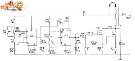
The electronic fishing shrimp machine circuit is composed of more than two multivibrators and high voltage generating circuit, and the circuit is shown as the chart. The low-frequency multivibrator is composed of one time-base IC of the dual time-base IC and resistors R1, R2, capacitors C1, C2, LED VL1, potentiometers RP1, RP2. When the oscillator works, VL1 shines. The high-frequency multivibrator is composed of the other time-base IC of the dual time-base IC and resistors R3, R4, light-emitting diode VL2, potentiometer RP3, capacitors C3, C4 and other components. When the oscillator works, VL2 shines. High-voltage generating circuit consists of the VM0S field-effect transistors VF1, VF2, resistors R7 ~ R11, Zener diode VS and step-up transformer T and so on.
(View)
View full Circuit Diagram | Comments | Reading(4024)
The electronic rodent repeller circuit diagram 4
Published:2011/6/14 20:31:00 Author:Lucas | Keyword: Electronic rodent repeller
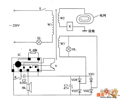
The electronic rodent repeller circuit is composed of the high voltage generating circuit and music alarm circuit, and the circuit is shown as the chart. High-voltage generating circuit is composed of the power switch S, light EL, indicator light HL, power transformer T, relay K and high voltage power grid. Music alarm circuit is composed of the music integrated circuit IC, transistor V, capacitors C1, C2, diodes VD1 ~ VD4 and speaker BL. Turning on the power switch S will make AC 220V voltage be limited by EL, transformed by T. And then it will generate 2kV high AC voltage on the winding W2 of T, and the voltage is added on high voltage electrified wire netting by the relay K; W3 winding generates 3.5V AC voltage and rectified by the VD1 ~ VD4, filtered by C1 to provide operating voltage for the IC at the same time of HL being lit.
(View)
View full Circuit Diagram | Comments | Reading(1040)
Agricultural non-tower pressurized water feeder circuit diagram 4
Published:2011/6/18 20:43:00 Author:Lucas | Keyword: Agricultural, non-tower, pressurized, water feeder
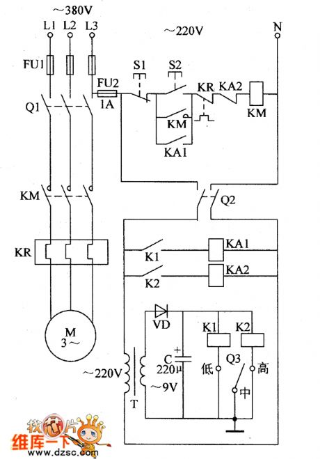
The agricultural non-tower pressurized water feeder circuit is composed of the power supply circuit and pressure detection control circuit, and the circuit is shown in Figure 1. Power supply circuit is composed of the fuse FU2, knife switch Q2, power transformer T, rectifier diode VD and filter capacitor C. Pressure detection control circuit consists of the electric contact pressure gauge Q3, relay Ka, intermediate relays KA1, KA2, AC contactor KM, thermal relay ER, control buttons S1, S2 and knife switch Q1 and so on. C selects the aluminum electrolytic capacitor with the voltage in 16V. VD chooses 1 N400 1 or 1 N4007 silicon rectifier diode. K1 and K2 select JRX-13F 9V DC relays.
(View)
View full Circuit Diagram | Comments | Reading(812)
Agricultural non-tower pressurized water feeder circuit diagram 3
Published:2011/6/18 20:37:00 Author:Lucas | Keyword: Agricultural, non-tower, pressurized , water feeder
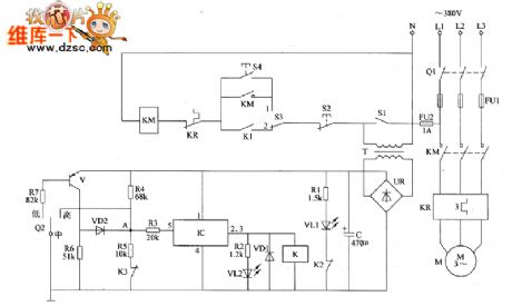
The agricultural non-tower pressurized water feeder circuit is composed of the power supply circuit, pressure detection circuit, control circuit and indication circuit, and the circuit is shown in Figure 1. Power supply circuit is composed of the knife switch Q1, fuses FU1, FU2, power switch S1, power transformer T, bridge rectifier UR and filter capacitor C. Pressure detection circuit consists of the electric contact pressure gauge Q2, resistors R4 ~ R7, the normally closed relay contacts K3 of relay K and transistor V. Control circuit consists of the electronic switch IC IC, diodes VD1, VD2, resistor R3, relay K, AC contactor KM, thermal relay ER, control button S2, manual / automatic control switch S3.
(View)
View full Circuit Diagram | Comments | Reading(1335)
Agricultural non-tower pressurized water feeder circuit diagram 2
Published:2011/6/18 20:32:00 Author:Lucas | Keyword: Agricultural , non-tower, pressurized , water feeder
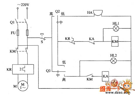
The agricultural non-tower pressurized water feeder circuit is composed of the knife switch Q1, fuse FU, relay KA, AC contactor KM, thermal relay ER, alarm HA, lights HL1, HL2, and the control contacts of pump outlet pressure gauge Q2, the control contacts of tank water level detection pressure gauge 03, and the circuit is shown as the chart 1. When people use water, the water level inside the tank will decrease down, and when the pressure below the set maximum pressure value, the moving contact of tank water level detection pressure gauge 03 and the upper contact are open, so KA releases, HL2 turns off. HL1 and HL2 use 220V power indicator lights.
(View)
View full Circuit Diagram | Comments | Reading(1114)
Agricultural non-tower pressurized water feeder circuit diagram 1
Published:2011/6/18 20:25:00 Author:Lucas | Keyword: Agricultural, non-tower , pressurized , water feeder
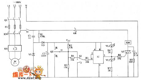
The agricultural non-tower pressurized water feeder circuit is composed of the power supply circuit and the detection control circuit, and the circuit is shown as the chart 1. Power supply circuit consists of the knife switch Q1, fuse FU, power switch S1, step-down capacitor C1, drain resistor R1, Zener diode VS, rectifier diode VD and filter capacitor C2. Detection control circuit is composed of electric contact pressure gauge Q2, resistors R2 ~ R9, capacitor C3, control switch S2, time-base integrated circuit IC, LEDs VL1, VL2, thyristor VT, AC contactor KM and thermal relay FR. R1 ~ R9 select 1/4W metal film resistors or carbon film resistors.
(View)
View full Circuit Diagram | Comments | Reading(713)
Electronic induced scorpion light circuit diagram
Published:2011/6/18 20:18:00 Author:Lucas | Keyword: Electronic, induced scorpion light
Electronic induced scorpion light circuit is composed of the transistor V, pulse transformer T2, resistor R, capacitors C1 ~ C4, light switch S2, power transformer T1, battery CB, bridge rectifier UR, power transformer T2 and the power switch S1, and the circuit is shown as the chart. T1, UR, C1, GB, and S1, S2 form power supply circuit. V, T2, R, C2 ~ C4 form the pulse oscillator circuit. R selects the 1/4W metal film resistor or carbon film resistor. C1 selects the aluminum electrolytic capacitor with the voltage in 16V ; C2 and C3 select high frequency ceramic capacitors; C4 uses the monolithic capacitor.
(View)
View full Circuit Diagram | Comments | Reading(2279)
| Pages:96/126 At 2081828384858687888990919293949596979899100Under 20 |
Circuit Categories
power supply circuit
Amplifier Circuit
Basic Circuit
LED and Light Circuit
Sensor Circuit
Signal Processing
Electrical Equipment Circuit
Control Circuit
Remote Control Circuit
A/D-D/A Converter Circuit
Audio Circuit
Measuring and Test Circuit
Communication Circuit
Computer-Related Circuit
555 Circuit
Automotive Circuit
Repairing Circuit