
Index 183
Aiwa J303g charger electricity principle diagram (double 1.2V quick charger circuits)
Published:2011/7/18 20:29:00 Author:TaoXi | Keyword: Aiwa, charger, electricity, principle diagram, double, 1.2, quick charger

In figure 2-17, the circuit uses the half-wave rectified pulsating current to charge the Nickel-cadmium batteries, the charging voltage has two stages. At the beginning of charging, S is in the 1 stage. When the battery is full, the light-emitting diode darkens gradually, so we need to choose the stage 2 to charge the battery in floating charging mode.
In order to speed up the charging speed, some chargers use the electronic circuit to realize the fast charging, it promotes the internal chemical reaction process of the battery by using the large current charging and the large current discharging. View from the charging effect, the common charge effect is better than the quick charge.
(View)
View full Circuit Diagram | Comments | Reading(660)
The low drift constant current circuit formed by MIC2951
Published:2011/7/20 22:11:00 Author:leo | Keyword: Low drift, constant current

As the picture shows, it is a low drift constant current circuit formed by MIC2951. Its output current is 1.23 V/R. In order to make the output current of MIC2951 lower than 150 mA, the accuracy of R should be 1%.
(View)
View full Circuit Diagram | Comments | Reading(692)
LM317 integrated circuit charger circuit
Published:2011/7/18 21:19:00 Author:TaoXi | Keyword: integrated, charger circuit
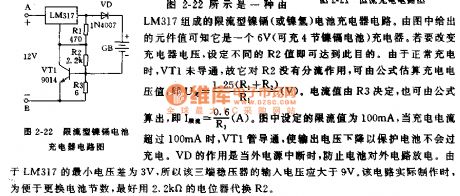
The constant current charging circuit which is composed of the three-port voltage stabilizer is as shown in figure 2-21. Because the electric potential difference of the LM317's pin-1 and pin-2 is 1.25V, if we ignore the shunting effects of R3, R1, LED, the potentiometer R2 can adjust the charging current value, the constant current value I=1.25/R2. In actual use, the R2 always uses the 1W resistance. When the R2 is 25Ω/1W, the charging current of the battery is about 50mA. The charging indicator circuit is composed of the resistor R1 and LED, if we choose the appropriate value of R3, when the battery has the required charging voltage, the VT1 will cut off, the LED will turn off. This circuit can charge more than four No.5 nickel-cadmium batteries.
(View)
View full Circuit Diagram | Comments | Reading(931)
555 time-base circuit adjustable power charger circuit
Published:2011/7/18 21:33:00 Author:TaoXi | Keyword: 555, time-base, adjustable, power, charger
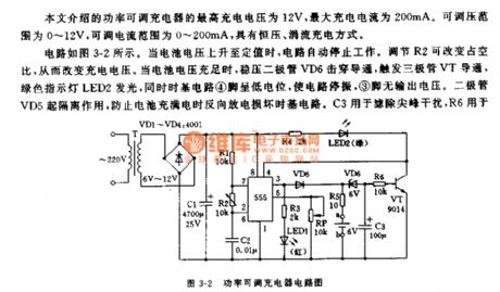
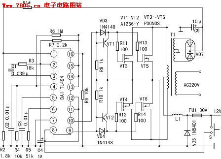
The adjustable power charger circuit which is introduced in this article has the highest charge voltage of 12V, the maximum charging current is 200mA. The adjustable voltage range is 0-12V, the adjustable current range is 0-200mA, and it has the constant voltage, trickle charging mode.
The circuit is as shown in figure 3-2. When the battery voltage rises to the set value, the circuit will stop operating. You can change the charging voltage by adjust the duty ratio of R2. When the voltage of the battery is full, the voltage-regulator diode VD6 punctures the conduction to trigger the conduction of the transistor VT, the green indicator light LED2 turns on, and the pin-4 of time-base circuit has the low level to stop the oscillation of the circuit, the pin-3 has no output voltage.
(View)
View full Circuit Diagram | Comments | Reading(982)
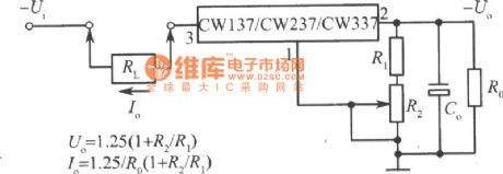
The adjustable constant current circuit formed by CW137/CW237/CW337
Published:2011/7/20 22:13:00 Author:leo | Keyword: Adjustable circuit, constant current
View full Circuit Diagram | Comments | Reading(656)
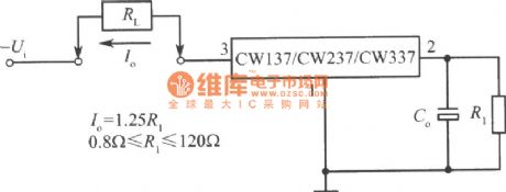
The constant current circuit formed by CW137/CW237/CW337
Published:2011/7/20 22:14:00 Author:leo | Keyword: constant current
View full Circuit Diagram | Comments | Reading(662)
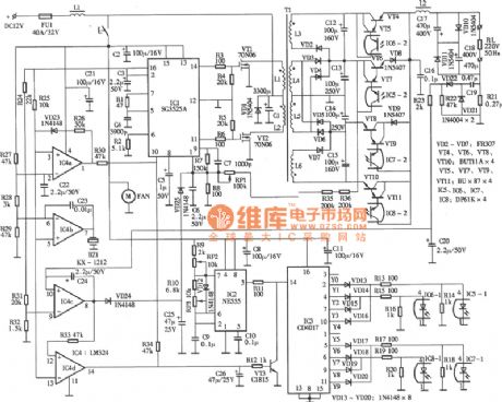
400W inverter circuit
Published:2011/7/18 21:42:00 Author:TaoXi | Keyword: 400W, inverter

The voltage stabilization sampling and error amplification system is composed of the pin-1 and pin-2, the positive phase input port pin-1 inputs the 15V DC voltage which is rectified and output by the inverter sub-sampling winding, and this 15V DC voltage is divided by R1 and R2 to supply the 4.7~5.6V sampling voltage to the inverter. The reverse phase input port pin-2 inputs the 5V reference voltage which is output by the pin-14. When the output voltage decreases, the voltage of pin-1 decreases too, the error amplifier outputs the low level to rise the output voltage through the PWM circuit. The voltage of pin-1 is 5.4V, the voltage of pin-2 is 5.0V, the voltage of pin-3 is 0.06V. At this time the output AC voltage is 235V (square wave voltage).
(View)
View full Circuit Diagram | Comments | Reading(2928)
3.0A-1.5A adjustable current charger circuit
Published:2011/7/18 22:20:00 Author:TaoXi | Keyword: adjustable, current, charger
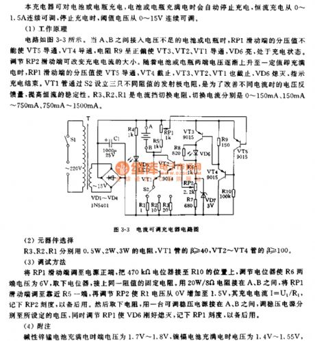
The circuit is as shown in figure 3-3. When the battery or storage battery which has lacking voltage is connected between A and B, the partial voltage value of the RP1's sliding port can not conduct VT5, the VT4 conducts, the resistance R9 is in the positive bias condition to conduct VT3, VT2, VT1, the VT6 turns on, the circuit is in the charging state. You can change the charging current by adjusting RP2's sliding port. As the voltage of the battery or the storage battery is gradually increased, the partial voltage value of the RP1's sliding port conducts VT5, the VT4, VT3, VT2, VT1 conduct, the VD6 turns off to indicate the end of charging. VT1 sets three emitter resistances with different resistance values through S2.
(View)
View full Circuit Diagram | Comments | Reading(694)
12V/5A storage battery automatic charging device
Published:2011/7/18 22:30:00 Author:TaoXi | Keyword: 12V/5A, storage battery, automatic, charging device
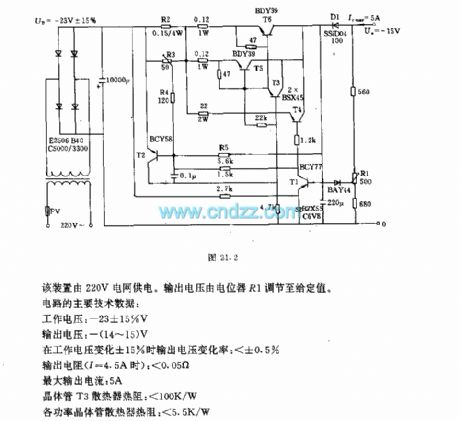
This device uses the 220V power grid as hte power supply. The output voltage is adjusted to the set value by potentiometer R1.
The main technical data:
Operating voltage:-23+/-15%V;Output voltage:-(14-15)V;Output voltage changing rate (when the operating voltage changing rate is +/-15%):<+/-0.5%;Output resistance (I=4.5A):<0.05Ω;Maximum output current:5A;Transistor T3 radiator thermal resistance:<100K/W;Each power transistor radiator thermal resistance:<5.5K/W.
(View)
View full Circuit Diagram | Comments | Reading(1134)
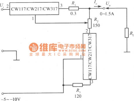
The constant current power resources circuit formed by CW117/CW217/CW317 (Output current is adjusted from zero)
Published:2011/7/20 22:26:00 Author:leo | Keyword: Constant current, power resources
View full Circuit Diagram | Comments | Reading(698)
Standard constant current power resources formed by CW117/CW217/CW317
Published:2011/7/20 22:33:00 Author:leo | Keyword: Constant current, power resource
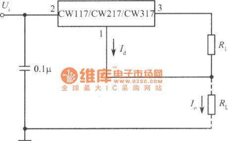
This integrated AVR has three adjustable ports with the lowest base voltage of 1.25 V which have perfect performance on keeping a steady output voltage. Besides, adjustable port has a super small current which is only about 50μA and super steady with a difference of 0.5 μA. Therefore, it can be used to form constant current and high frequency circuit. Its output current is Id plus 1.25/R1. Id is small so Io can be regarded as about 1.25/R1. (View)
View full Circuit Diagram | Comments | Reading(663)
500 MA USB compatible Nimh battery charge control circuit--CN3058
Published:2011/7/12 5:12:00 Author:chopper | Keyword: 500 MA, USB compatible, Nimh battery, charge control, Section 1-4, high efficiency
Overview :CN3058 is a charger circuit which can charge rechargeable batteries like single lithium iron phosphate in constant current/voltage mode.The device includes power transistor,and its application does not require the external current detective resistor and blocking diode.CN3058 only requires few external components,and works under USB bus technology specifications,thus it is ideal for portable applications.Heat modulation circuit can control the chip temperature within safety range if the power consumption of devices is bigger or the environmental temperature is higher. (View)
View full Circuit Diagram | Comments | Reading(1163)
The 100 W to 200 W inverted power supply circuit
Published:2011/7/20 23:56:00 Author:leo | Keyword: 100 W to 200 W, inverted power supply

100 to 200 W inverted power supply circuit
(View)
View full Circuit Diagram | Comments | Reading(691)
Power special inverting power supply, inverter
Published:2011/7/12 5:14:00 Author:chopper | Keyword: Power, special, inverting power supply, inverter
(View)
View full Circuit Diagram | Comments | Reading(1129)
New type sine wave inverted power supply circuit
Published:2011/7/20 23:52:00 Author:leo | Keyword: Sine wave, inverted power supply
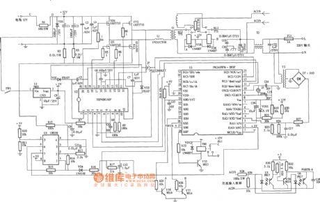
New type sine wave inverted power supply circuit (View)
View full Circuit Diagram | Comments | Reading(1618)
The 300W inverted power supply circuit which is able to connect with inductive load
Published:2011/7/20 23:55:00 Author:leo | Keyword: 300W inverted power supply, connecting with inductive load
The 300W inverted power supply circuit which is able to connect with inductive load
(View)
View full Circuit Diagram | Comments | Reading(1346)
The constant voltage power resources circuit formed by MAX610 series AC/DC chip(no transformer)
Published:2011/7/20 22:59:00 Author:leo | Keyword: Constant voltage, no transformer
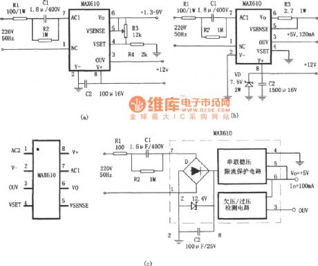
As the picture shows, this circuit is the no transformer constant voltage power resources circuit formed by MAX610 series AC/DC chip. Picture (a) is the power resources with adjustable voltage and picture (b) is power resources with extending current. MAX610 series is a type of single chip and low power DC/AC convertor which has the following features: the standard output voltage is 5 V± 0.2V and the current is 75μA with over current protection.
(View)
View full Circuit Diagram | Comments | Reading(1093)
The constant voltage power resources circuit formed by PS0500—5(No transformer)
Published:2011/7/20 22:53:00 Author:leo | Keyword: No transformer, constant voltage
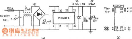
As the picture shows, this circuit is the no transformer constant voltage power resources circuit formed by PS0500-5. PS0500-5 is a 2.5 W small high frequency AC/DC converting module. It does not need power supply transformer but only outer rectifier and filter. It can offer DC voltage of 5 V and DC current of 500 mA. Its package is DIP40 with 8 ports which you can see in the picture.
(View)
View full Circuit Diagram | Comments | Reading(851)
500MA current charge,USB compatible charging management integrated circuit--CN3068
Published:2011/7/12 5:13:00 Author:chopper | Keyword: 500MA current, USB compatible, charging management, integrated circuit
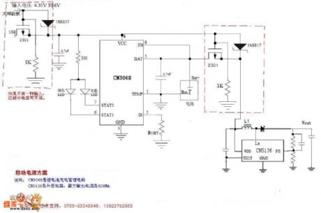
Overview :CN3068 is a charger circuit which can charge single rechargeable lithium battery in constant current/voltage mode.The device includes power transistor,and its application does not require the external current detective resistor and blocking diode.CN3069 only requires few external components,and works under USB bus technology specifications,thus it is ideal for portable applications.Heat modulation circuit can control the chip temperature within safety range if the power consumption of devices is bigger or the environmental temperature is higher. (View)
View full Circuit Diagram | Comments | Reading(2233)
Solar energy mobile solution
Published:2011/7/12 5:13:00 Author:chopper | Keyword: Solar energy, mobile solution, 6V
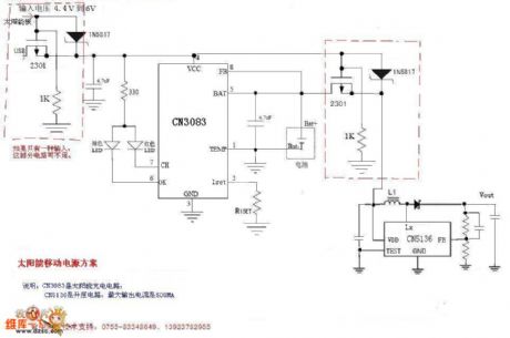
Overview :CN3083 is a single lithium battery charge management chip which can be powered with solar panels.The device includes power transistor,and its application does not require an external current detective resistor and blocking diode.The internal 8-bit analog-digital conversion circuit can automatically adjust the charge current by the current output capability of input voltage supply.Users need not consider the worst case, and it can maximize the use of the current output capability of input voltage supply.And it is suitable for the lithium battery charger application powered by voltage supply whose current output capacity is limited such as solar panel.
(View)
View full Circuit Diagram | Comments | Reading(2381)
| Pages:183/291 At 20181182183184185186187188189190191192193194195196197198199200Under 20 |
Circuit Categories
power supply circuit
Amplifier Circuit
Basic Circuit
LED and Light Circuit
Sensor Circuit
Signal Processing
Electrical Equipment Circuit
Control Circuit
Remote Control Circuit
A/D-D/A Converter Circuit
Audio Circuit
Measuring and Test Circuit
Communication Circuit
Computer-Related Circuit
555 Circuit
Automotive Circuit
Repairing Circuit