
Index 184
various battery charger chips powered by solar--CN3082
Published:2011/7/12 5:12:00 Author:chopper | Keyword: battery charger chips, powered, solar, satisfy, characteristics
Overview :CN3082 is a charger control circuit which can charge various batteries like single lithium batteries,single lithium iron phosphate or two to four NiMH rechargeable batteries.The device includes power transistor,and its application does not require the external current detective resistor and blocking diode.CN3082 only requires few external components, and works under USB bus technology specifications,thus it is ideal for portable applications.Heat modulation circuit can control the chip temperature within safety range if the power consumption of devices is bigger or the environmental temperature is higher. (View)
View full Circuit Diagram | Comments | Reading(1126)
μPC1099 switching power supply circuit
Published:2011/7/11 2:34:00 Author:chopper | Keyword: switching, power supply circuit
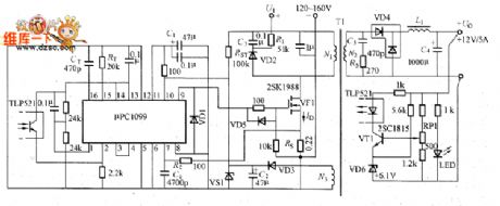
Figure shows the pPC1099 switching power supply.μPC1099 is the switching power supply integrated controller in PWM mode.And it is applied to the primary side control circuit whose main switching components adopt power MOSFET,and the main features are that:it can directly drive the power MOSFET; it is the totem-pole output circuit whose peak output current is 1.2A;it has the fast current of high-impedance;it is the over-current limiting circuit;its oscillation frequency is 50~500kHz;it has the over-voltage protection function and remote control;it uses ⑩-pin DIP and SOP packages.
(View)
View full Circuit Diagram | Comments | Reading(2097)
current resonant converter circuit
Published:2011/7/11 2:33:00 Author:chopper | Keyword: current, resonant converter
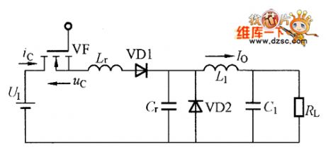
Resonant converter is the core of the soft switching power supply circuit.Resonant converters include current resonance,voltage resonance,quasi-resonance of class E,part resonance and so on.Current resonant switch is the most normal way of soft switches, and has developed a number of circuits, and has entered a practical phase.The picture shows the typical instance of current resonant converter,and it is current resonant circuit based on step-down converter.
(View)
View full Circuit Diagram | Comments | Reading(778)
Adjustable Voltage Power Supply Circuit of Thyristor
Published:2011/7/19 11:21:00 Author:Michel | Keyword: Adjustable Voltage, Power Supply Circuit
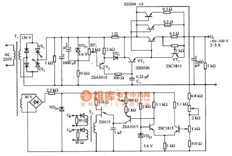
The adjustable voltage power supply circuit of the thyristor is shown as above.The circuit output voltage is 50~100V and the current is 3A.The high voltage parts adopt VS1 and VS2 tubes and they are used as crystal phase control.It is corresponding to the output voltage and load change and it controls waveform dutyfactor,and it can improve the linear regulator's transformation efficiency. VT2 and VT3 are current limit circuit,VT1 has current limiting function and C1 is vibration preventing capacitance.The circuit output voltage is 70 V, and its load current is 0 ~ 2 A and its voltage changes within ±3V. (View)
View full Circuit Diagram | Comments | Reading(3490)
Over-voltage Protection Circuit of High Voltage Power Supply
Published:2011/7/19 11:20:00 Author:Michel | Keyword: High Voltage Power Supply, Over-voltage Protection Circuit
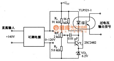
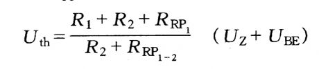
The picture 49 is over-voltage protection circuit of high voltage power supply circuit.The over-voltage power supply is provided by output voltage and the work current is around 2mA.In the circuit ,if Ucc voltage is judged as over-voltage,the protection action begins and Uth
formula is .RRP1-2 is the voltage between RP1 sliding end and R2 point,Uz is VD1 stable voltage an d UBE is VT1's base-emitter voltage.This circuit outputs photoelectric coupler TLP521-1 and it isolates.Thus,it can also be used for the ac power of over-voltage protection (View)
View full Circuit Diagram | Comments | Reading(890)
Low Power Consumption Monocell Boost Circuit
Published:2011/7/20 3:12:00 Author:Joyce | Keyword: Low Power Consumption, Monocell , Boost
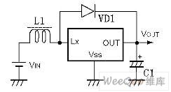
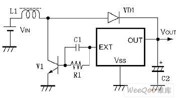
Series RH5RH / 5 RI (product of Japan Ricoh Corporation) is a boost-dedicated switching regulator for fixed output. It only needs inductance, diode and capacitance to get fixed boost output. The good feature of this circuit is that it has low power consumption (4 ~ 15 uA), and it can function properly under the circumstance of 0.9 V low input voltage
SeriesRH5RI and RH5RH are the frequency modulation model (PFM) and pulse width modulation (PWM) three-terminal boost switching regulator ICs respectively. It includes series RH5RIxx1 (RH5RHxx1) in which drive is contained within the IC and series RH5RIxx2 (RH5RHxx2) in which drive is connected externally.
As shown in the following figure is the basic external circuit diagram of RH5RI and RH5RH.
When the drive has a large load, it can be connected externally as shown in the figure . (View)
View full Circuit Diagram | Comments | Reading(637)
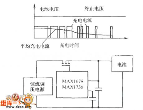
Charging circuit composed of the MAXl678/MAXl736
Published:2011/7/11 2:24:00 Author:TaoXi | Keyword: Charging circuit
View full Circuit Diagram | Comments | Reading(576)
5V/1A Constant AC Stabilized Voltage Power Supply Circuit
Published:2011/7/13 7:25:00 Author:Michel | Keyword: 5V/1A, Constant AC , Stabilized Voltage, Power Supply Circuit
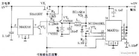
The above picture is 5V/1A constant AC stabilized voltage power supply circuit.The circuit can still provide 5V/1A power supply in 80 minutes when 5V main power supply is off.MAX709 is monitoring circuit and the feet 7 outputs high PWL and transistor VT is in conduction state when its feet 2 monitors main power supply.The DC/DC converter MAX720 is in shut-off mode and VT1 and VT2 charge batteries.Feet 7 outputs low PWL and VT2 and VT3 stop and MAX720 is in work mode and constant power output increases to 5V when main power supply decreases to MAX709 offsetting threshold level(typical value is 4.65V). (View)
View full Circuit Diagram | Comments | Reading(1544)
Small Power Uninterrupted Power Supply Circuit
Published:2011/7/13 7:24:00 Author:Michel | Keyword: Small Power, Uninterrupted, Power Supply Circuit
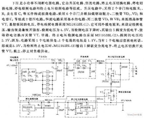
The above picture is a small power uninterrupted power supply circuit.It consists of lift circuit, constant current circuit, terminate circuit, switching circuit, power switching circuit, power switching circuit, power detection circuit and termination voltage detection circuit etc.In the lift circuit,the two longest-serving outfield and resistance R2, R1and capacitance C1 constitute oscillating circuit and it uses six longest-serving outfield in parallel way to strengthen the drive ability.Diode VD1 and VD2 and capacitance C2 constitute 2 times voltage circuit.Constant current circuit uses basic circuit, diode VD3 and VD4 to offset voltage between the transistor VT1 and basic emitting.The blackout detection circuit, M5193BL (1) can use set the external resistance,R3 to set detecting voltage and the output is a very open type, detection set voltage is 4.5 V. (View)
View full Circuit Diagram | Comments | Reading(651)
Automatic charging, power supply dual-use device circuit (2)
Published:2011/7/14 22:17:00 Author:TaoXi | Keyword: Automatic, charging, power supply, dual-use, device circuit

Operating principle:
The circuit is as shown in figure 4-3, this device uses three pieces of integrated circuits: IC1 is the LM317, the adjustable voltage stabilization power supply is composed of LM317 and other surrounding components, the adjustment range is 1.25V-15V; IC2 is the pulse oscillator which is composed of the time base circuit 555, the duty ratio is 60%; IC3 is the high current and low current charging and discharging conversion control circuit.
After you pressing the button AN, the battery voltage is lower than the gate voltage of D, so D outputs the high level, the transistor V4 conducts, the relay K closes to form the self-protection.
(View)
View full Circuit Diagram | Comments | Reading(581)
The Automatic charger circuit
Published:2011/7/21 0:55:00 Author:TaoXi | Keyword: Automatic, charger circuit

Automatic charger circuit
The automatic charger circuit which is composed of the VT1 charging circuit and the LM324 control circuit is as shown in figure 2-23, the charging loop is composed of the VD1, VD2, R5, VT1 and the batteries, the charging current is the pulsating current, it is controlled by the R5. The LM324 is the voltage comparator, the in-phase port has the comparison voltage and it is set by the potentiometer RP; the reverse phase voltage value is decided by the number of the rechargeable batteries, for example, when you are charging 2 nickel cadmium batteries, the comparison voltage can be set to 3V. The reverse phase pin-2 of LM324 is connected with the battery positive port through the resistor R4.
The power supply of LM324 is composed of VD2 and C1.
(View)
View full Circuit Diagram | Comments | Reading(1214)
12V/6A charging circuit with excellent charge curve and auto-cutout circuit
Published:2011/7/21 0:54:00 Author:TaoXi | Keyword: 12V/6A, charging circuit, excellent charge curve, auto-cutout circuit
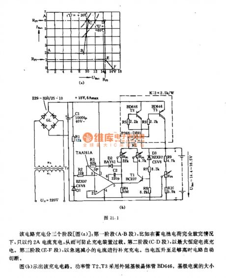
The charging process of this circuit is divided into three stages (figure a): stage one, when the storage battery has no residual electric charge, you can charge the battery with 2A current to prevent the overload of the charging device. Stage 2 (C-D), you need to charge the battery with the largest constant current. Stage 3 (E-F), you need to charge the battery with rapid decreasing current. When the voltage is high enough, the circuit will cut off automatically.
Figure b is the charging circuit. The power tubes T2 and T3 use the epitaxy base electrode transistor BD646, the base electrode current has relationship with the load current.
(View)
View full Circuit Diagram | Comments | Reading(1533)
Constant current-constant voltage dual-function charger circuit
Published:2011/7/18 21:51:00 Author:TaoXi | Keyword: Constant current, constant voltage, dual-function, charger
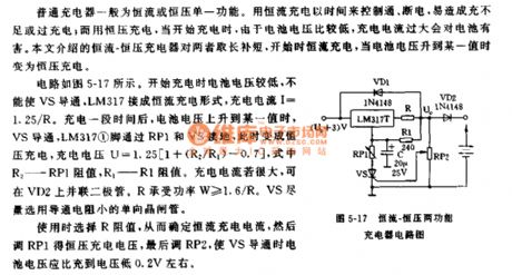
The ordinary charger has the single function of the constant current charging or constant voltage charging. The circuit is as shown in figure 5-17. When the charging begins, the voltage of the battery istoo low to conduct the VS, the LM317 is connected into the form of constant current charging, the charging current I=1.25/R. When the voltage of battery invreases to the certain value, VS conducts, the pin-1 of LM317 is connected with the ground through the RP1 and VS, at this time, the charging mode is the constant voltage charging, the charging voltage U=1.25(1+R2/R1-0.7), R2 is the resistance value of RP1, R1 is the resistance value of R1. If the charge current is very large, you can connect a diode on VD2 in parallel connection state. The power handling of R is W》/=1.6/R. VS need to use the unidirectional thyristor with the small conduction resistance.
(View)
View full Circuit Diagram | Comments | Reading(887)
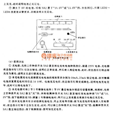
Multi-functional charger circuit (1)
Published:2011/7/18 21:52:00 Author:TaoXi | Keyword: Multi-functional, charger
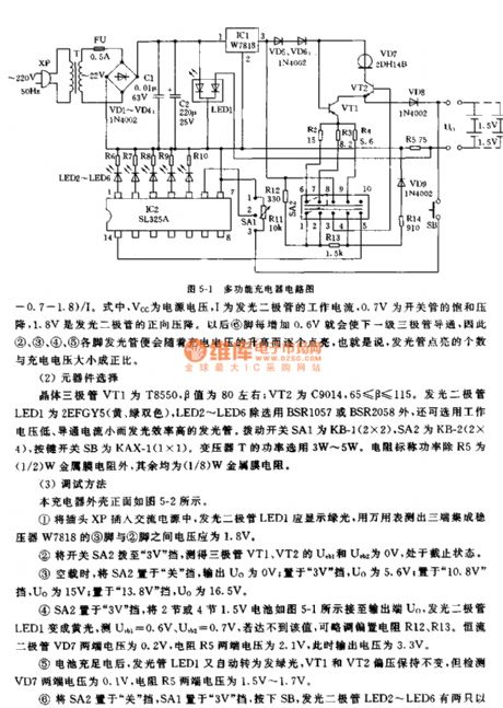
Operating principle:
The circuit is as shown in figure 5-1. You connect the charged battery with the output port Vo, then turn on the power, the transistor VT1 will conduct, the collector electrode of it gets the constant current to charge the battery through the diode VD8. The resistances R12 and R13 are the biasing resistors of the transistor VT2, when the VT2 is in the conduction state, the collector electrode produces the constant collector current because it is connected with the diode VD7, and the constant collector current is output to the collector electrode of transistor VT1 through the emitter, it is used as the load current of VT1 to meet the constant current battery charging. THe VD7 is the constant current diode.
(View)
View full Circuit Diagram | Comments | Reading(673)
VMOS tube switching power supply application circuit (2)
Published:2011/7/13 23:01:00 Author:TaoXi | Keyword: VMOS tube, switching, power supply, application circuit

The VMOS tube switching power supply application circuit is as shown in the figure. Because this circuit uses the voltage comparator 710, the circuit is simplier than former circuits. In this figure, the resistances R1, R2, R3 and the regulator tubes VDl, VD2 form the partial voltage and voltage stabilization circuit, it divides the three groups of voltage (5V, 6V and 18V) from the 28V input voltage to be used as the power of 710; the power soft start-up circuit is composed of the resistances R12, R13, the capacitor C13, the diodes VD6, VD7 and the transistor VT3. In the moment of the power is connecting, the drive pulse width of the VMOS tube VTl increases exponentially.
The rated DC output voltage of this power supply is 5V, the output current is 10A, the operating frequency is 200kHz. (View)
View full Circuit Diagram | Comments | Reading(675)
Electronic transformer
Published:2011/7/13 23:13:00 Author:TaoXi | Keyword: Electronic transformer
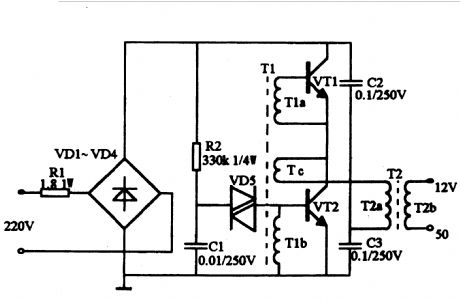
The circuit is as shown. The operating principle is the same as the switching power supply, the diodes VD1~VD4 forms the rectifier bridge and this rectifier bridge changes the city electricity into the DC, the high frequency oscillation circuit is copmosed of the oscillation transformer T1, the transistors VT1 and VT2, and this high frequency oscillation circuit changes the pulse DC into the high-frequency current, then the high-frequency high-voltage pulse is reduced by the ferrite output transformer T2 to get the voltage and power. R1 is the current limiting resistor. The start trigger circuit is composed of the resistance R2, the capacitance C1 and the two-way trigger diode VD5. The transistors VT1 and VT2 use the S13005, the B is 15~20 times. Also you can use the BUceo>=35OV high power transistor such as the C3093.
(View)
View full Circuit Diagram | Comments | Reading(4500)
Fixed DC Power Supply Diagram3
Published:2011/5/20 3:10:00 Author:Nora | Keyword: Fixed, DC , Power
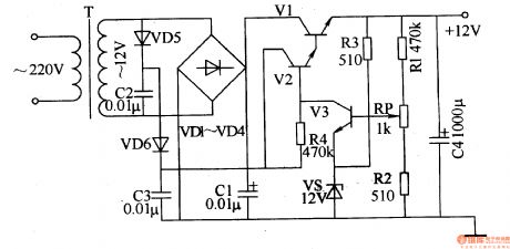
AC 220V step-down voltage by T in T, to generate AC 12V secondary winding voltage, the voltage all the way through VDl-VD4 bridge rectifier, Cl Vl filter Bo Houjia to the collector on; another path VD5, VD6 and C2 , C3 times the pressure of the rectified voltage to provide work for the V2. V2 turn, its output voltage of the emitter turn-Vl, the output from the Vl + l2V emitter voltage. When Vl emitter output voltage when the high side at + l2V, V3 conduction capacity enhancement, so that the base voltage V2 goes low, Vl and V2 in the conduction diminished capacity, the output voltage down to normal; when Vl emitter When the output voltage is low, V3 conduction diminished capacity, V2 increase the base voltage, so that Vl and V2 in the conduction capacity enhancement, the output voltage to normal.
(View)
View full Circuit Diagram | Comments | Reading(748)
Unattended storage battery automatic power supply device circuit
Published:2011/7/14 22:17:00 Author:TaoXi | Keyword: Unattended, storage battery
The operating principle:
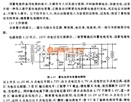
This device has two parts: one part is composed of the step-down transformer, the rectifier stack, the voltmeter, the ammeter; another part is the control part.
The circuit is as shown in figure 4-32. The 220V city electricity is reduced by the transformer and is rectified by the diode to charge the storage battery, when the voltage of storage battery increases to 14.2V, the potential of A point is 4.37V, the potential of B point is 4.7V, the potential of A point is higher than the B point, the op-amp IC is the voltage comparator, so the IC outputs the low level, the transistor VT cuts off, the relay K loses the electric and the transformer disconnected the 220V city electricity, the charging stops.
(View)
View full Circuit Diagram | Comments | Reading(675)
Phase Detection and Double Direction Counting Circuit of EPC-755A
Published:2011/7/13 7:08:00 Author:Michel | Keyword: Phase Detection, Double DirectionCounting, Circuit

EPC-755A photoelectric encoder has good performance and has good anti-interference in angle and displacement measuring.EPC-755A photoelectric encode also owns stable and reliable output pulse signal, and the pulse signal can be obtained after the count is measured in digital signal.On the steering wheel rotation angle measurement EPC-755 A photoelectric encoder is chosen as sensor when we develop a driving simulator in the car.Its output circuit chooses open collector and output resolution selects 360 pieces of pulses/circles,which can be clockwise and counterclockwise,considering the steering wheel rotation is bidirectional,and it can be counted after detecting the output signal of the encoder. (View)
View full Circuit Diagram | Comments | Reading(1128)
MAX8596Z Switching Regulator Driving Eight White LED Circuit
Published:2011/7/11 23:33:00 Author:Michel | Keyword: White LED Circuit
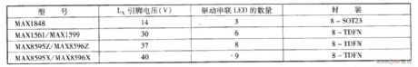
When the series white LED are driven,the LED can get homogeneous brightness because the flowing current is equal.The defect of driving voltage is that driving voltage is the sum of each LED postive voltage.The driver's ouput voltage amplitude should satisfy the series LED driving voltage.This series configuration needs to use inductive boost switch converter, in order to obtain high efficiency when it's high voltage.When we choose this type of converter,LX pins rated output voltage should be taken into consideration.
The table gives a few rated voltage of inductive boost switch converter Lx pins and drivable series white LED numbers. (View)
View full Circuit Diagram | Comments | Reading(532)
| Pages:184/291 At 20181182183184185186187188189190191192193194195196197198199200Under 20 |
Circuit Categories
power supply circuit
Amplifier Circuit
Basic Circuit
LED and Light Circuit
Sensor Circuit
Signal Processing
Electrical Equipment Circuit
Control Circuit
Remote Control Circuit
A/D-D/A Converter Circuit
Audio Circuit
Measuring and Test Circuit
Communication Circuit
Computer-Related Circuit
555 Circuit
Automotive Circuit
Repairing Circuit