
Index 264
MOSFET resonant DC / DC converter circuit diagram
Published:2011/4/1 3:49:00 Author:Nicole | Keyword: converter
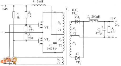
The figureof a MOSFET resonant DC / DC converter circuit isas below. In this circuit, the transformer is operating in unsaturation mode, with arc changes through the grid feedback voltage of MOSFET, by reducing the grid voltage to make MOSFET flip.
(View)
View full Circuit Diagram | Comments | Reading(3369)
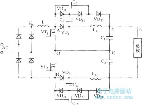
With zero current transition soft-switching power supply circuit diagram
Published:2011/4/1 3:48:00 Author:Nicole | Keyword: soft-switching power supply
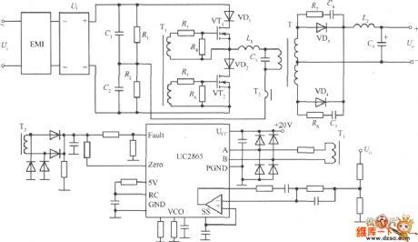
The figure of a zero current transition soft-switching power supply practical circuit as below: single-phase AC input; output DC; main switchadopts MOSFET; power converteradopts half bridge circuit; integrated control chipadopts UC2865; power conversion adopts zero current transformation circuit.
(View)
View full Circuit Diagram | Comments | Reading(2583)
Stabilized voltage and stabilized current circuit use intergrated circuit
Published:2011/3/30 1:26:00 Author:may | Keyword: Stabilized voltage and stabilized current
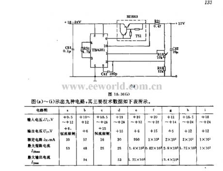
View full Circuit Diagram | Comments | Reading(642)
5V/2A isolated switching power supply circuit diagram
Published:2011/4/6 3:15:00 Author:Nicole | Keyword: switching power supply, isolated
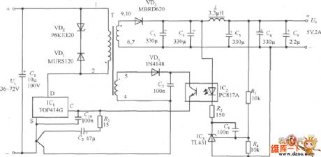
The circuit diagram as shown. C1 stands for the input filter capacitor. VDz and VD1 formonce sideclamp protection circuit. R1 is the resistance of the controlled end, C2 is a bypass capacitor. C10 is paralleled between TOP414GC-S-side to prevent high frequency interference occurring in the control side and caused power circuit malfunction. VD2 represents the output rectifier diodes, C3, C4, L, C5 and C6 form the output filter, C9 for the output Noise capacitor. External error amplifier is composed of the shunt regulator TL431. When the output voltage fluctuations, the samples obtained after R3, R4 partial pressure, compared with TL431 voltage reference, resulting in an external control signal, and then through the optical coupler PC817A to change TOP414G control terminal current, thereby regulating the track duty stabilize the Uo. Control loop gain is set by the R2. After VD3, C7 rectifier filter, the feedback winding voltage give the infrared receiver of PC817A power supply.
(View)
View full Circuit Diagram | Comments | Reading(6439)
3000VA inverter power supply circuit
Published:2011/3/31 21:32:00 Author:may | Keyword: inverter power supply
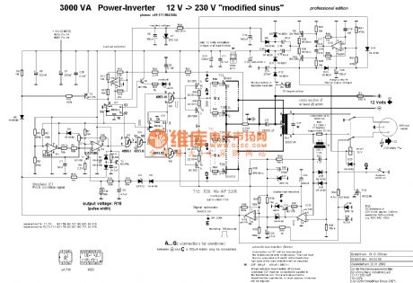
View full Circuit Diagram | Comments | Reading(2321)
13V stabilized voltage supply composed of μ7812
Published:2011/3/29 20:27:00 Author:may | Keyword: stabilized voltage supply
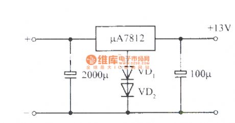
13V stabilized voltage supply composed of μ7812 adopts diode to upgrade output voltage. (View)
View full Circuit Diagram | Comments | Reading(774)
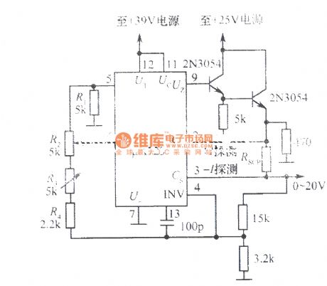
0~20V Adjustable power supply composed of μA723
Published:2011/3/29 20:33:00 Author:may | Keyword: Adjustable power supply
View full Circuit Diagram | Comments | Reading(909)
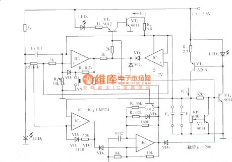
New type Ni-Cd battery charger circuit schematic diagram
Published:2011/4/11 22:24:00 Author:Nicole | Keyword: Ni-Cd battery, charger
View full Circuit Diagram | Comments | Reading(1365)
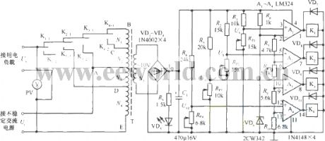
Automatic AC voltage regulator
Published:2011/4/11 3:47:00 Author:Nicole | Keyword: AC voltage regulator
View full Circuit Diagram | Comments | Reading(3842)
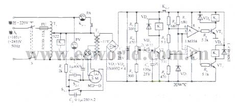
Automatic AC regulated power supply
Published:2011/4/11 3:46:00 Author:Nicole | Keyword: regulated power supply
View full Circuit Diagram | Comments | Reading(602)
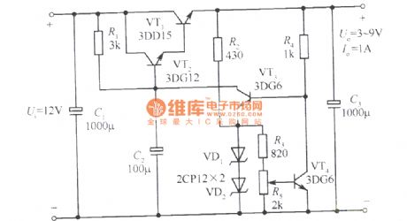
3~9V adjustable regulated power supply circuit with 1 sampling ratio
Published:2011/4/11 3:44:00 Author:Nicole | Keyword: regulated power supply, sampling ratio
View full Circuit Diagram | Comments | Reading(923)
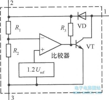
Under-voltage special integrated chip MC3X164 series internal circuit diagram
Published:2011/4/11 3:39:00 Author:Nicole | Keyword: under-voltage, integrated chip
View full Circuit Diagram | Comments | Reading(584)
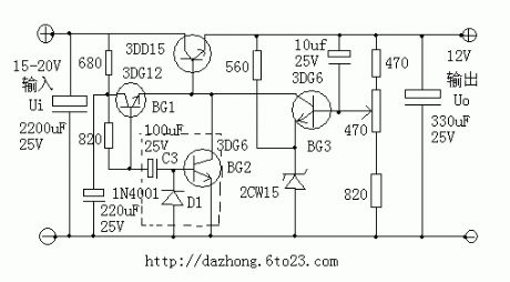
Soft start regulated power supply
Published:2011/4/11 3:35:00 Author:Nicole | Keyword: soft start, regulated power supply
View full Circuit Diagram | Comments | Reading(835)
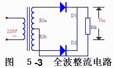
Full wave commutate circuit
Published:2011/4/11 3:41:00 Author:Nicole | Keyword: Full wave commutate
View full Circuit Diagram | Comments | Reading(650)
Three-level passive lossless soft-switching PFC circuit topology
Published:2011/4/11 3:13:00 Author:Nicole | Keyword: passive lossless soft-switching, PFC
View full Circuit Diagram | Comments | Reading(2424)
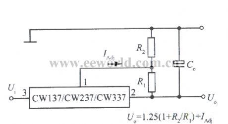
Standard application circuit of three terminal adjustable negative output voltage integrated regulator
Published:2011/4/11 3:11:00 Author:Nicole | Keyword: negative output voltage, integrated regulator
View full Circuit Diagram | Comments | Reading(518)
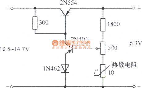
6V regulated power supply circuit worked in the temperature range of -55℃~71℃
Published:2011/4/11 3:06:00 Author:Nicole | Keyword: regulated power supply, temperature range
View full Circuit Diagram | Comments | Reading(731)
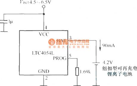
Button type rechargeable lithium ion battery charging circuit
Published:2011/4/11 3:03:00 Author:Nicole | Keyword: lithium ion battery, button type
View full Circuit Diagram | Comments | Reading(687)
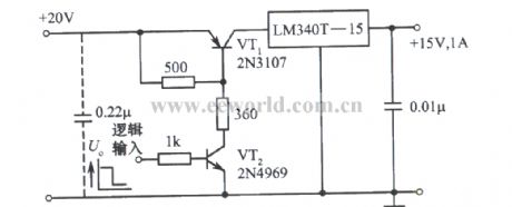
Logic level control regulated power supply
Published:2011/4/11 2:39:00 Author:Nicole | Keyword: Logic level control, regulated power supply
View full Circuit Diagram | Comments | Reading(525)
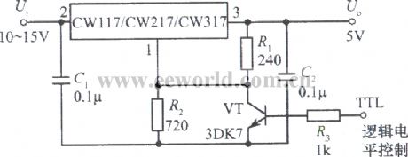
Logic control integrated regulated power supply
Published:2011/4/11 2:38:00 Author:Nicole | Keyword: logic control, regulated power supply
View full Circuit Diagram | Comments | Reading(561)
| Pages:264/291 At 20261262263264265266267268269270271272273274275276277278279280Under 20 |
Circuit Categories
power supply circuit
Amplifier Circuit
Basic Circuit
LED and Light Circuit
Sensor Circuit
Signal Processing
Electrical Equipment Circuit
Control Circuit
Remote Control Circuit
A/D-D/A Converter Circuit
Audio Circuit
Measuring and Test Circuit
Communication Circuit
Computer-Related Circuit
555 Circuit
Automotive Circuit
Repairing Circuit