
Protection Circuit
Index 5
LOW_BATTERY_PROTECTOR
Published:2009/7/6 5:58:00 Author:May
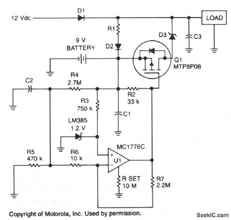
To prevent battery damage due to over-dis-charge, a low-voltage detector and switch should be included in the design of the battery backup circuit.The detector circuit should consume extremely low current. The switch should exhibit a low-voltage drop and be easy to control.
R1 and D2 provide a trickle charge for the battery. Chosen for its low forward voltage drop, Schottky diode D3 prevents forward polarization of the diode incorporated in Q1. When the battery voltage is above approximately 8 V, the output of U1 is low and Q1 is turned on. If the battery voltage falls below 8 V, the output of U1 increases and turns off Q1. (View)
View full Circuit Diagram | Comments | Reading(2400)
Commercial power safe voltage protector circuit diagram
Published:2011/8/2 2:43:00 Author:Rebekka | Keyword: Commercial power safe voltage protector
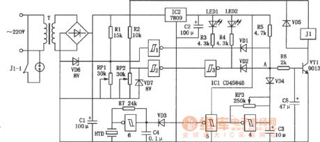
The protector can cut off the power supply automatically and and issue intermittent alarm sound and lighting instructions when the main power protector is lower or higher than the set voltage. The circuit plays the role of automatic protection for household appliances. (View)
View full Circuit Diagram | Comments | Reading(1305)
AUTOMATIC_POWER_DOWN_PROTECTION_CIRCUIT
Published:2009/7/6 5:30:00 Author:May
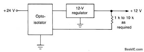
This circuit is faster than a fuse and automatically resets itself when a short is removed. The normal regulated dc input line is opened and the phototransistor of the opto isolator is connected in series with the source and regulator. Between the output of the regulator and ground is a LED and an associated current-limiting resistor, placed physically close to the surface of the photosensitive device. As long as the regulator is delivering its rated output, the LED glows and causes the photo device to have a low resistance. Full current is thus allowed to flow. If a short circuit occurs on the output side of the regulator, the LED goes dark, the resistance of the photo device increases, and the regulator shuts off. When the short is removed, the LED glows, and the regulator resumes operation. (View)
View full Circuit Diagram | Comments | Reading(806)
Voltage photoelectric sensor broken circuit and open phase protection circuit diagram
Published:2011/8/2 2:36:00 Author:Rebekka | Keyword: Voltage photoelectric sensor, broken circuit, open phase protection
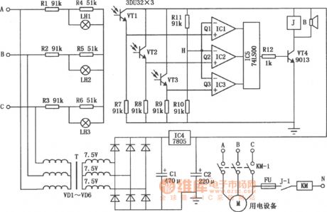
The circuit is voltage photoelectric sensor type three-phase broken circuit protector. It will make alarm sound and cut off the power supply automatically. The circuit is shown as above. (View)
View full Circuit Diagram | Comments | Reading(3262)
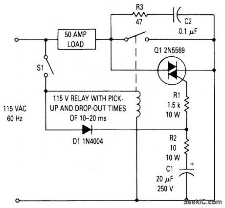
TRIAC_RELAY_CONTACT_PROTECTION
Published:2009/7/6 3:19:00 Author:May
Circuit Notes
This circuit can be used to prevent relay contact arcing for loads up to 50 amperes.There is some delay between the time a relay coil is energized and the time the contacts close. There is also a delay between the time the coil is de-energized and the time the contacts open. For the relay used in this circuit both times are about 15 ms. The TRIAC across the relay contacts will turn on as soon as sufficient gate current is present to fire it. This occurs after switch S1 is closed but before the relay contacts close. When the contacts close, the load current passes through them, rather than through the TRIAC, even though the TRIAC is receiving gate current. If 51 should be closed during the negative half cycle of the ac line, the TRIAC will not turn on immediately but will wait until the voltage begins to go positive, at which time diode Dl conducts providing gate current through R1. The maximum time that could elapse before the TRIAC turns on is 8-1/3 ms for the 60 Hz supply. This is adequate to ensure that the TRIAC will be on before the relay contact closes. (View)
View full Circuit Diagram | Comments | Reading(1348)
Power Supply Protection Circuit of TL431
Published:2011/7/24 7:11:00 Author:Michel | Keyword: Power Supply, Protection Circuit
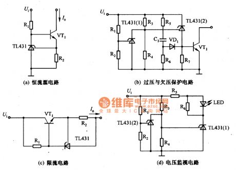
The a,b,c,d are power supply protection circuits of TL431.The picture (a) is constant current circuit of TL431 and the constant current I。=UREF/R2.Picture (b) is protection circuit of overvoltage and undervoltage and the voltage is equal to (1+R3/R4)UREF+UBE,when it is under voltage,the voltage is equal to (1+R1/R2)UREF when it is overvoltage.In the formula,UBE is the base-emiting voltage of VT1.Picture (c) is the current-limiting circuit and the limitting current I。=UREF/R2.Picture(d) is voltage monitoring circuit and LED displays when the voltage is lower than (1+R3/R4)UREF and higher than (1+R1/R2)UREF. (View)
View full Circuit Diagram | Comments | Reading(4541)
25 ohm speakers overload protection circuit diagram
Published:2011/5/10 1:17:00 Author:Rebekka | Keyword: speakers overload protection
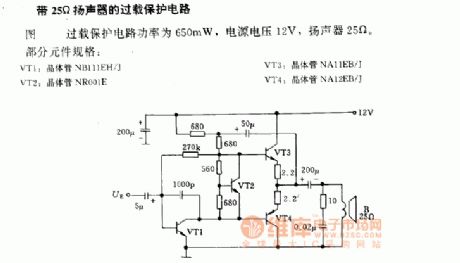
25 ohm speakers overload protection circuit diagramThe power of overload protection is 650mW, power supply voltage is 12V, speaker 25ohm.Part of the component specifications:VT1: Transistor NB111EH/JVT2: Transistor NR001ETV3: Transistor NA11EB/JVT4: Transistor NA12EB/J (View)
View full Circuit Diagram | Comments | Reading(2008)
POWER_SUPPLY_PROTECTION_CIRCUIT
Published:2009/7/3 3:21:00 Author:May
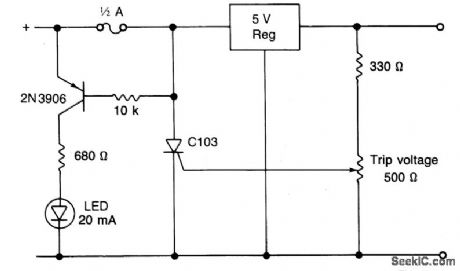
Circuit NotesWhen using a regulated supply to reduce a supply voltage there is always the danger of component failure in the supply and consequent damage to the equipment. A fuse will protect when excess current is drawn, but might be too slow to cope with overvoltage conditions. The values shown are for a 12 V supply being dropped to 5 V. The trip voltage is set to 5.7 V to protect the equipment in the event of a regulator fault. The 330 ohm resistor and the 500 ohm potentiometer form a potential divider which samples the output voltage as set by adjustment of the potentiometer. The SCR is selected to carry at least twice the fuse rating. The full supply voltage is connected to the input of the regulator. The 2N2906 is held bias off by the 10 k resistor and the SCR so that the LED is held off. If the output voltage rises above a set trip value then the SCR will conduct, the fuse will blow, and the 2N3906 will be supplied with base current via the 10 k resistor, and the LED will light up. (View)
View full Circuit Diagram | Comments | Reading(1011)
OVERVOLTAGE_PROTECTION_CIRCUIT_SCR_CROWBAR
Published:2009/7/3 3:08:00 Author:May
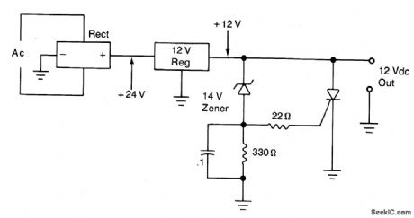
Circuit Notes
The silicon controllqd rectifier (SCR) is rated to handle at least the current of the power supply. It is connected in parallel across the 12 V dc output lines, but remains inert until a voltage appears at the gate terminal. This triggering voltage is supplied by the zener diode. At potentials less than 14 V the zener will not conduct current. But, at potentials greater than 14 Vdc the zener conducts and creates a voltage drop across the 330 ohm resistor that will fire the SCR. When the SCR turns on, the output lines of the power supply are shorted to ground. This will blow the primary fuse or bum out the transformer if there is no primary fuse. (View)
View full Circuit Diagram | Comments | Reading(2187)
ELECTROMETER_AMPLIFIER_WITH_OVERLOAD_PROTECTION
Published:2009/7/1 4:22:00 Author:May
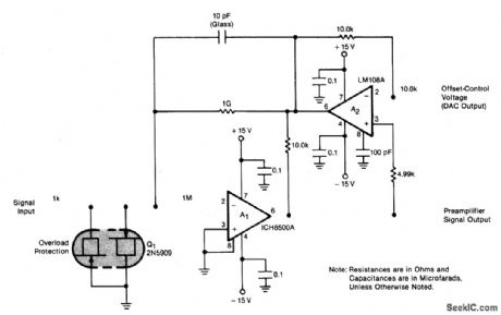
The preamplifier is protected from excessive input signals of either polarity by the 2N5909 junction field-effect transistor. A nulling circuit makes it possible to set the preamplifier output voltage to zero at a ftxed low level (up to ±10-8A) of the input current. (This level is called the standing current and corresponds to the zero-signal level of the instrumentation.) The opposing (offset) current is generated in the 109 feedback resistor to buck the standing current. Different current ranges are reached by feeding the preamplifter output to low and high gain amplifter chains. To reduce noise, each chain includes a 1.5 Hz corner active filter. (View)
View full Circuit Diagram | Comments | Reading(1422)
SPEAKER_OVERLOAD_PROTECTOR
Published:2009/7/1 4:22:00 Author:May
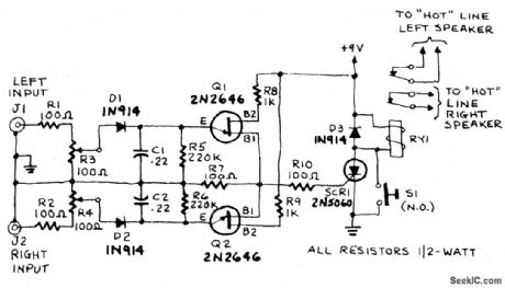
The input to the circuit is taken from the amplifier's speaker-output terminals or jacks. If the right-channel signal is sufficiently large to charge C1 to a potential that is greater than the breakdown voltage of Q1's emitter, a voltage pulse will appear across R7. Similarly, if the left-channel signal is sufftciently large to charge C2 to a potential that is greater than the breakdown voltage of Q2's emitter, a pulse will appear across R7. The pulse across R7 triggers SCR1, a sensitive gate SCR (IGT less than 15 mA where IGT is the gate trigger-current), that latches in a conducting state and energizes RY1. The action of the relay will interrupt both speaker circuits, and the resulting silence should alert you to the problem. Cut back the volume on your amplifier, then press and release S1 to reset the circuit and restore normal operation. The circuit can be adjusted to trip at any level from 15 to 150 watts RMS. To calibrate, deliberately feed an excessive signal to the right input of the speaker protector and adjust R3 until RY1 energizes. Do the same with the left channel, this time adjusting R4. The circuit is now calibrated and ready for use. (View)
View full Circuit Diagram | Comments | Reading(1312)
The Circuit of TV Steady Pressure Protection Used in Countryside
Published:2011/5/6 1:39:00 Author:May | Keyword: TV Steady Pressure Protection
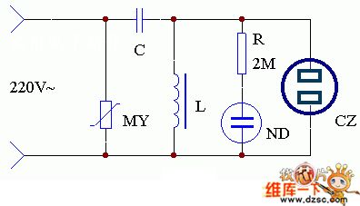
The application of this set is shown in the diagram. As the voltage of transmission network in the countryside is not very stable now, you can homemade a simple AC magnetic saturation regulator device. You can merge a varister MY in the input end of AC constant voltage regulator. It can protect the TV from overvoltage and let TV work more stable. Using the AC voltage regulator in thunderstorm days can protect the TV from striking by lightning.
(View)
View full Circuit Diagram | Comments | Reading(650)
PROTECTION_FOR_ORP_TUNING
Published:2009/6/28 22:41:00 Author:May
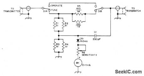
Simple resistive SWR bridge provides dummy load, relative power output indicator, and safe method of tuning transmitter without destroying transistors because of mismatched load. Input divider R1-R4 has total resistance of 50 ohms, using 1/2-W composition resistors, for dissipating transmitter output when S1 is in TUNE position. M1 indicates relative power applied to this load. Antenna is connected through Transmatch, and antenna tuner is adjusted for minimum deflection or lowest SWR. RE isolates transmitter from antenna. With S1 in OPERATE position, M1 indicates relative power output into antenna.-A S. Woodhull, Simplified Output Metering Protects QRP Transmitters, QST, April 1977, p 57. (View)
View full Circuit Diagram | Comments | Reading(2456)
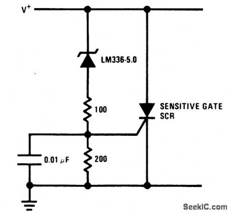
5_V_CROWBAR
Published:2009/6/28 22:39:00 Author:May
View full Circuit Diagram | Comments | Reading(1)
FAST_ACTING_POWER_SUPPLY_PROTECTION
Published:2009/6/28 22:38:00 Author:May
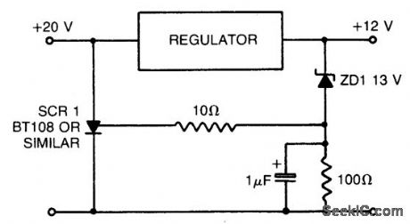
When using a regulated power supply to reduce a supply voltage, there is always the danger that component failure in the power supply might lead to a severe overvoltage condition across the load. To cope with overvoltage situations, the circuit is designed to protect the load underovervoltage conditions. Component values given are for a 20 V supply with regulated output at 12 V. The zener diode can be changed according to whatever voltage is to be the maximum. If the voltage at the regulator output rises to 13 V or above, the zener diode breaks down and triggers the thyristor which shorts out the supply line and blows the main fuse. (View)
View full Circuit Diagram | Comments | Reading(874)
OVERVOLTAGE_PROTECTION_FOR_LOGIC
Published:2009/6/28 22:37:00 Author:May
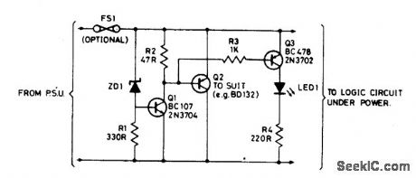
Zener diode ZD1 senses the supply, and the should the supply rise above 6 V, Q1 will turn on. In turn, Q2 conducts clamping the rail. Subsequent events depend on the source supply. It will either shut down, go into current limit or blow its supply fuse. None of these will damage TTL chips. The rating of Q2 depends on the source supply, and whether it will be required to operate continuously in the event of failure. Its current rating has to be in excess of the source supply. (View)
View full Circuit Diagram | Comments | Reading(1023)
OVERVOLTAGE_PROTECTION_WITH_AUTOMATIC_RESET
Published:2009/6/28 22:35:00 Author:May
View full Circuit Diagram | Comments | Reading(918)
POWER_PROTECTION_CIRCUIT
Published:2009/6/28 22:30:00 Author:May
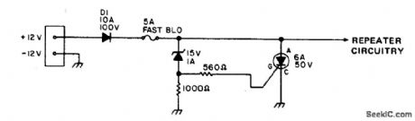
To safeguard portable, emergency power repeaters from reverse or excessive voltage, D1 prevents incorrect polarity damage, and zener voltage determines the maximum voltage that will reach the rest of the circuitry.Use fast blowing fuse rated greater than the SCR current rating. (View)
View full Circuit Diagram | Comments | Reading(746)
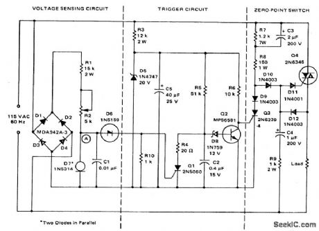
ELECTRONIC_CROWBAR_FOR_AC_OR_DC_LINES
Published:2009/6/28 22:29:00 Author:May


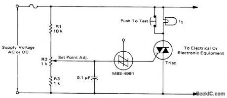
For positive protection ofelectrical or electronic equipment, use this against excessive supply voltage. Due to improper switching, wiring, short circuits, or failure of reg-ulators, an electronic crowbar circuit can quickly place a short circuit across the power lines, thereby dropping the voltage across the protected device to near zero and blowing a fuse. The triac and SBS are both bilateral devices, the circuit is equally useful on ac or dc supply lines. With the values shown for R1, R2, and R3, the crowbar operating point can be adjusted over the range of 60 to 120 volts dc or 42 to 84 volts ac. The resistor values can be changed to cover a different range of supply voltages. The voltage rating of the triac must be greater than the highest operating point as set by R2. I1 is a low power incandescent lamp with a voltage rating equal to the supply voltage. It may be used to check the set point and operation of the unit by opening the test switch and adjusting the input or set point to fire the SBS. An alarm unit such as the Mallory Sonalert may be connected across the fuse to provide an audible indication of crowbar action.(This circuit may not act on short, infrequent power line transients). (View)
View full Circuit Diagram | Comments | Reading(1682)
1IC_REGULATOR_PROTECTION
Published:2009/6/23 3:56:00 Author:May
This circuit protects an IC regulator against various fault conditions. (View)
View full Circuit Diagram | Comments | Reading(0)
| Pages:5/12 123456789101112 |
Circuit Categories
power supply circuit
Amplifier Circuit
Basic Circuit
LED and Light Circuit
Sensor Circuit
Signal Processing
Electrical Equipment Circuit
Control Circuit
Remote Control Circuit
A/D-D/A Converter Circuit
Audio Circuit
Measuring and Test Circuit
Communication Circuit
Computer-Related Circuit
555 Circuit
Automotive Circuit
Repairing Circuit