
Protection Circuit
Index 9
Dual-tone phone 160,168 controller circuit
Published:2011/6/29 2:28:00 Author:Fiona | Keyword: Dual-tone phone, controller
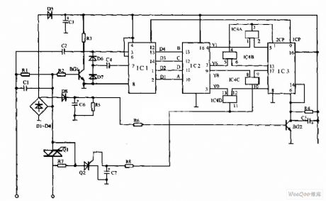
Dual-tone phone 160,168 controller circuit is shown as below,the function of this controller is the same with the controller's.The two controllers' basic principle is:add a homemade electronic switch between telephone and switchboard,only the user who officially calls 160,168 information desk can make the electronic switch be connected.
(View)
View full Circuit Diagram | Comments | Reading(766)
Irrigation motor automatic protector circuit diagram 1
Published:2011/6/14 4:15:00 Author:Lucas | Keyword: Irrigation motor, automatic protector
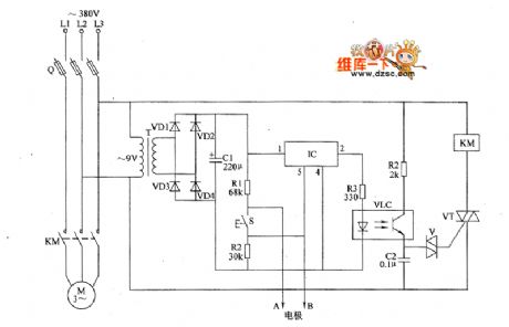
The irrigation motor automatic protector circuit is composed of the power supply circuit and the detection / protection control circuit, and the circuit is shown as the figure. Power supply circuit is composed of the power transformer T, rectifier diodes VD1 ~ VD4 and filter capacitor C1. Detection / protection circuit is composed of the detection electrodes A, B, Start button S, resistors R1 ~ R4, capacitor C2, optocoupler VLC, bi-directional trigger diode V, thyristor VT, electronic switch IC IC and AC contactor KM. AC 380V voltage is bucked by T, rectified by VDI ~ VD4 and filtered by C1 to provide 9V DC voltage for the electronic switch IC IC. RI ~ RZI select l/4W metal film resistors.
(View)
View full Circuit Diagram | Comments | Reading(1184)
Irrigation motor automatic protector circuit diagram 2
Published:2011/6/14 4:19:00 Author:Lucas | Keyword: Irrigation motor, automatic protector
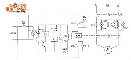
The irrigation motor automatic protector circuit is composed of the starter control circuit, phase failure protection circuit and test circuit, and the circuit is shown as the figure. Starting circuit is composed of the starter button S2 (S2a, S2b), AC contactor KM and relay K2 and so on. Phase failure protection circuit is composed of the indicators HL2 ~ HL4, photosensitive diode VD1, resistor R, transistor V, capacitor C, diode VD2, power transformer T and the relay K1. Test circuit consists of the test button Sl, light sensitive diode VD1 and indicator light HL1. R selects 1/4W metal film resistor or carbon film resistor. C uses the aluminium electrolytic capacitor with the voltage in 25V.
(View)
View full Circuit Diagram | Comments | Reading(1851)
Light load Energy Saver of Motor(the 1st)
Published:2011/5/19 8:04:00 Author:Felicity | Keyword: Light load Energy Saver of Motor,
Work of the circuit
Once it is powered, 380V AV voltage will be supplied to motor M through reator LTl-LT3. In the same time current transformer TA will produce sensor signal voltage which will make V1 and V2 saturated conducted. Then the motor will work with full voltage. When the motor is work it maybe has light load or even no load. So the sensor signal voltage on current transformer TA will reduce and this leads to the motor's decompressed operation. When the motor's load is becoming heavier, and the sensor signal voltage on current transformer TA reaches a vertain figure, the motor will work with full voltage. (View)
View full Circuit Diagram | Comments | Reading(700)
Motor protector circuit diagram 17
Published:2011/5/29 2:01:00 Author:Lucas | Keyword: Motor protector
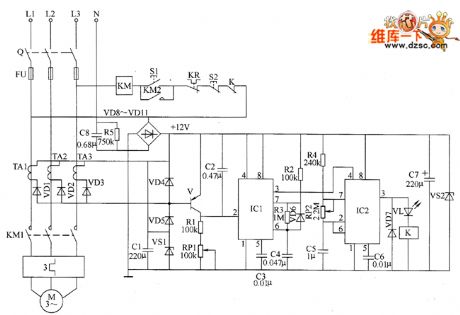
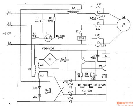
The motor protection circuit is composed of the phase pulse detection circuit, monostable trigger circuit, control circuit and power supply circuit, the circuit is shown as the chart. Phase pulse detection circuit is composed of the current transformers TA1 ~ TA3, diodes VD1 ~ VD5, Zener diode VS1 and capacitor C1. Monostable trigger circuit is composed ofthe transistor V, resistors R1 ~ R3, potentiometer RP1, capacitors C2 ~ C4, diode YD6 and time-based integrated circuit IC1. Delay control circuit is composed of the time-base integrated circuit IC2, resistor R4, capacitors C5, C6, diode VD7, light-emitting diode VL, relay K and AC contactor KM and other components. Power supply circuit consists of step-down capacitor C8, resistor R5, rectifier diodes VD8 ~ VD11, filter capacitor CT and blocking diode VS2.
(View)
View full Circuit Diagram | Comments | Reading(1113)
Motor protector circuit diagram 14
Published:2011/5/29 2:01:00 Author:Lucas | Keyword: Motor protector
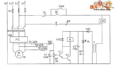
The motor protector circuit is composed of the power detection circuit and phase failure protection circuit, the circuit is shown as the chart. Power circuit is composed of the power transformer T, rectifier diode VD3, filter capacitor C2, current limiting resistor M and LED VL. Phase failure detection protection circuit consists of resistors R1 ~ R3, capacitor C1, diodes VD1, VD2, potentiometer RP, transistors V1, V2 and relays Κ and so on. R1 ~ R3 select 1/2W metal film resistors; Ⅲ uses the carbon film 1/4W resistor or metal film resistor. RP selects membrane potentiometer or variable resistor. C1 and C2 select aluminium electrolytic capacitor with the voltage in 16V. VD1 ~ VD3 select 1N4004 or 1N4007 diode rectifier. VL uses φ5mm ordinary light-emitting diode.
(View)
View full Circuit Diagram | Comments | Reading(899)
Motor protector circuit diagram 13
Published:2011/5/29 2:03:00 Author:Lucas | Keyword: Motor protector
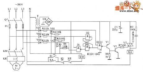
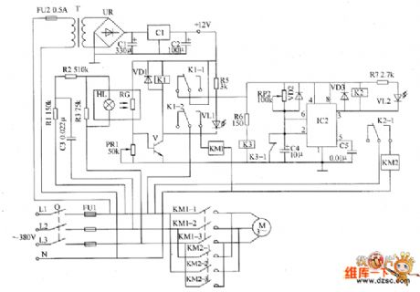
The motor protector circuit is composed of the power circuit, phase sequence detection circuit, trigger, and protection control circuit, the circuit is shown as the chart. Power circuit is composed of the power transformer T, bridge rectifier UR and filter capacitor C1. Phase sequence detection circuit is composed of the diodes VD1 ~ VD3, resistors R1 ~ R6 and Zeners VS1 ~ VS3. Trigger is composed of the D1 ~ D4 in the NAND gate IC. Protection control circuit consists of transistors V1, V2, resistors R7 ~ R9, capacitor C2, thyristor VT, and relay KA. Start button S1, stop button S2, knife switch Q, fuse FU, thermal relays KR and KM form the original control circuit of motor. R1 ~ R3 and R9 select 1W metal film resistors; M ~ R8 select 1/4W carbon film resistor or metal film resistors.
(View)
View full Circuit Diagram | Comments | Reading(2403)
Motor protector circuit diagram 6
Published:2011/6/8 3:55:00 Author:Lucas | Keyword: Motor protector
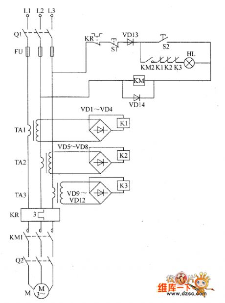
The motor protector circuit is composed of the current transformers TA1 ~ TA3, thermal relay KR, rectifier diodes VD1 ~ VD14, relays K1 ~ K3, start button S1, stop button S2 and AC contactor KM, the circuit is shown as the chart. After the the knife switch Q1 is turned on and the start button S2 is pressed, 380V AC voltage between the phase line L2 and L3 is added to the AC contactor KM by the normally closed contacts of relay KR, stop button S1, diode D13 and start button QO, and KM will operate normally, and its normally open contacts ( action contacts) KM1 and KM2 are connected, at this time if the knife switch Q2 is connected, the motor M will be energized operation. VD1 ~ VD14 use 1N4007 silicon rectifier diodes. K1 ~ K3 select JRX-13F 12V small relays. KM uses 220V or 380V AC contactor. HL uses 220V, 60W incandescent bulb.
(View)
View full Circuit Diagram | Comments | Reading(763)
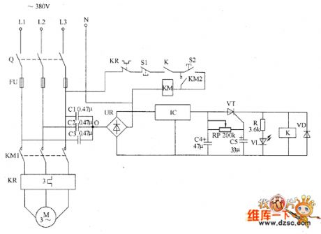
Motor protector circuit diagarm 3
Published:2011/6/2 3:38:00 Author:Lucas | Keyword: Motor protector
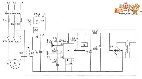
Motor protector circuit is composed of the power circuit, current detection circuit and protection control circuit, and the circuit is shown as the chart. Power supply circuit is composed of the power transformer T, bridge rectifier UR, filter capacitor C5, and the current limiting resistor R3 and regulator diode VS. Current detection circuit is composed of the current transformer TA, diode VD1, capacitor C1 and potentiometers RP1, RP2. Protection control circuit is composed of the time base control circuit IC IC, resistors R1, R2, diode VD2, capacitors C2 ~ C4, AC contactor K and relay KM. S1 is the stop button, S2 is the start button. R1 and R2 select 1/4W carbon film resistors; R3 uses 1W metal film resistor. RP1 uses WHW sealed membrane variable resistor; RP2 uses WSW organic solid variable resistor.
(View)
View full Circuit Diagram | Comments | Reading(902)
Motor protector circuit diagarm 5
Published:2011/6/1 20:02:00 Author:Lucas | Keyword: Motor protector
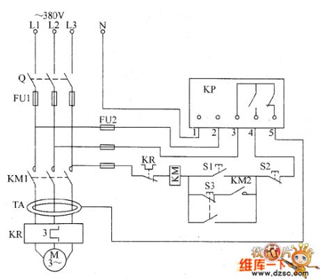
The motor protector circuit is composed of the ring current transformer TA, protection relay KP, start button S1, stop button S2, inching button S3, AC contactor KM and thermal relay KR and other components, and the circuit is shown as the FU1. Turning on the start button S1 will make KM get power and lock-hold, and the motor M will get power and operate; if pressing the inching button KR53 will make the M get power and operate. M will be turned off after A3 being reset. When one phase of the three-phase AC power supply open occurs phase, AC power contactor KM will be released, and the motor M stops to protect the motor and prevent their damage from phase running. When the motor M is over-current or overload, thermal relay KR operates to make the KM release and M stop.
(View)
View full Circuit Diagram | Comments | Reading(2220)
Motor protector circuit diagarm 4
Published:2011/6/1 20:07:00 Author:Lucas | Keyword: Motor protector
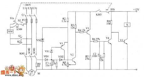
The motor protector circuit is composed of the current detection control circuit and delay control circuit, and the circuit is shown as the chart. Current detection control circuit is composed of the resistors R0 ~ R5, transistors V1 ~ 171VJ, capacitor C1, diodes VD1 and VD2, Zener diode VS1 and VS2. Delay control circuit consists of resistors R6 ~ R8, capacitor C2, transistors V4, V5 and relay Κ. S1 is the start button, S2 is the stop button, KM is the AC contactor. R0 selects 20W wire wound resistor; R1 ~ R8 select 1/4W metal film resistors. RP uses film variable resistor. C1 and C2 select aluminum electrolytic capacitors with the voltage above 10V. VD1 and VD2 use 1N4007 silicon rectifier diodes. VS1 and VS2 use 1W silicon Zener diodes.
(View)
View full Circuit Diagram | Comments | Reading(817)
The motor protector circuit diagram 1
Published:2011/6/1 7:14:00 Author:Lucas | Keyword: motor protector
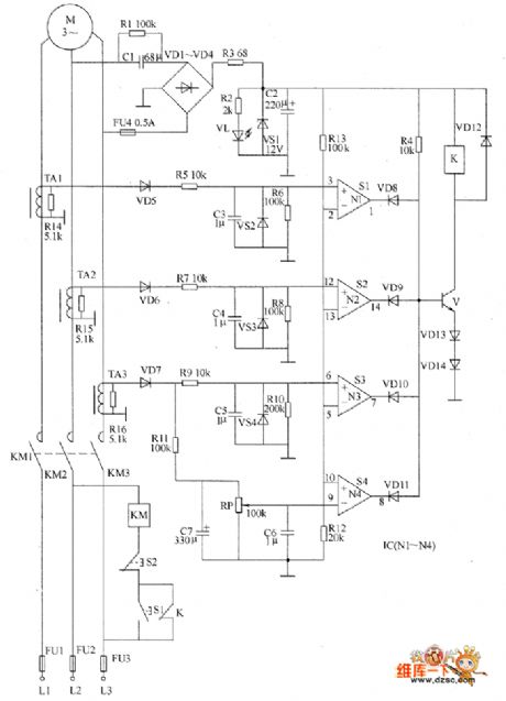
The motor protection circuit is composed of the power supply circuit, current detection circuit and protection control circuit, and the circuit is shown as the chart. Power supply circuit consists of capacitors C1, C2, resistors R1 ~ R3, rectifier diodes VD1 ~ VD4, Zener diode VS1 and power indicator LED VL. Current detection circuit is composed of the current transformers TA1 ~ TA3, resistors R5 ~ R11, R14 ~ R16, diodes VD5 ~ VD7, voltage regulator diodes VS2 ~ VS4, potentiometer RP, capacitors C3 ~ C7 and so on. Protection control circuit is composed of the operational amplifier integrated circuit IC (N1 ~ N4), resistors M, R12, R13, diodes VD8 ~ VD14, transistor V, relays K, AC contactor KM, start button S1, stop button S2 and so on.
(View)
View full Circuit Diagram | Comments | Reading(823)
The motor protector circuit diagram 2
Published:2011/6/1 7:19:00 Author:Lucas | Keyword: motor protector
The motor protection circuit is composed of the DC power supply circuit, phase sequence detection circuit, sampling control circuit and automatic commutation circuit, and the circuit is shown as the chart. DC power supply circuit is composed of the fuse FU2, power transformer T, bridge rectifier UR, filter capacitors C1, C2, and three-terminal voltage regulator integrated circuit IC1. Phase sequence detection circuit is composed of the capacitor C3, resistors R1 ~ R3 and indicator light HL. Sampling control circuit consists of the photosensitive resistor RC, potentiometer RP1, transistor V, relay K1, diode VD1, resistor R5, LED VL1 and AC contactor KM1 and so on. R1 ~ R5 and R7 use 1/4W carbon film resistors or metal film resistors; R6 uses 1/2W metal film resistor.
(View)
View full Circuit Diagram | Comments | Reading(1478)
Motor protector circuit diagram 18
Published:2011/5/20 20:35:00 Author:Lucas | Keyword: Motor protector
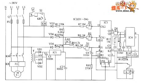
The motor protection circuit is composed of the power circuit, phase sequence detection circuit, monostable circuit and control implementation circuit, the circuit is shown as the chart. Power circuit is composed of the power transformer T, rectifier diodes VD1, VD2, capacitors C1, C2, and three-terminal voltage regulator integrated circuit IC1. Phase sequence detection circuit is composed of the diodes VD3 ~ VD5, resistors R1 ~ RIO, capacitor C6, four NAND gate Schmitt trigger integrated circuit IC2 (D1 ~ D4) and dual JK master-slave flip-flop integrated circuit IC3. Monostable circuit is composed of the resistors R11 ~ R13, capacitors C3 ~ C5 and time-based integrated circuit IC4. Control implementation circuit is composed of the resistor R14, transistor V, diode VD6 and relay K and other components. Knife switch Q, fuse FU, AC contactor KM and KR form the origin control circuit of motor M .
(View)
View full Circuit Diagram | Comments | Reading(3235)
Motor protector circuit diagram 16
Published:2011/5/20 21:04:00 Author:Lucas | Keyword: Motor protector
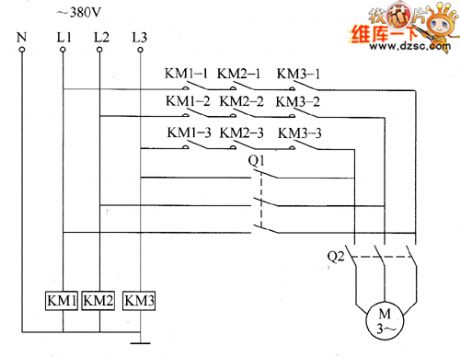
The motor protector circuit is composed of the AC contactors KM1 ~ KM3, knife switches Q1, Q2 and motor M, the circuit is shown as the chart. When 380V AC supply voltage is normal, the AC contactors KM1 ~ KM3 get power and pull in, their 3 groups of normally open contacts are connected, then closing the knife switch Q2 will make motor M get power and operate. When the AC 380V voltage is open-phase because of thunder or other reasons, one contactor of KM1 ~ KM3 couldn't pull in or get power, the power supply circuit of motor M will cut off to protect the motor M. For example, the voltage on L2 phase line disappears, AC contactor KM2 releases, the normally open contacts KM2-1 ~ KM2-3 cut off. KM1 ~ KM3 select the 220V AC voltage contactor.
(View)
View full Circuit Diagram | Comments | Reading(903)
Motor protector circuit diagram 15
Published:2011/5/20 22:03:00 Author:Lucas | Keyword: Motor protector
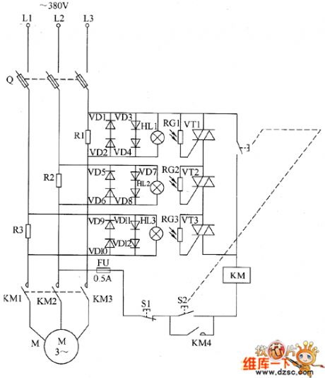
The motor protector circuit detection circuit is composed of the current sampling circuit and light control protection circuit, the circuit is shown as the chart. Current sampling detection circuit consists of sampling resistors R1 ~ R3. Light control protection circuit is composed of the protection diodes VD1 ~ VD12, small bulbs HL1 ~ HL3, photosensitive resistors RC1 ~ RC3 and thyristors VT1 ~ VT3. Q is the fuse knife switch, FU is fuse, S1 is stop button, S2 is the start button, KM is the AC contactor. R1 ~ R3 select 5 ~ 1OW wire wound resistors, the resistance should be based on the rated power of motor. If it uses 1.5kW motor, the rated current is about 3A, the sampling resistors can be set at 0.3Ω. RG1 ~ RG3 use MC45 series of light-sensitive resistors. VD1 ~ VD12 use 1N5408 silicon rectifier diodes. VT1 ~ VT3 select MAC97A6 bidirectional thyristors.
(View)
View full Circuit Diagram | Comments | Reading(793)
Motor protector circuit diagram 8
Published:2011/5/21 1:44:00 Author:Lucas | Keyword: Motor protector
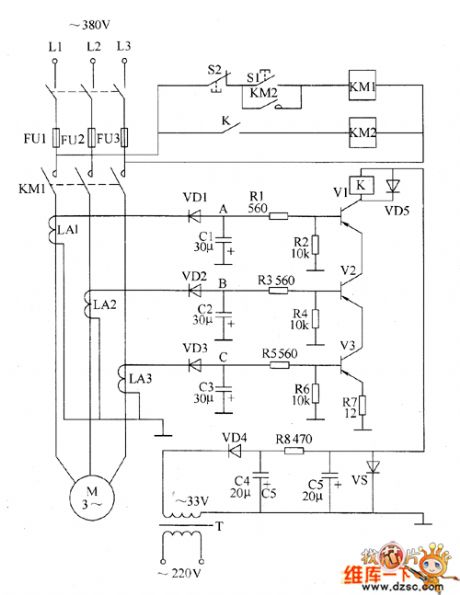
The motor protection circuit is composed of power supply circuit, current detection circuit and protection control circuit, the circuit is shown as the chart. Power circuit is composed of the power transformer T, rectifier diode VD4, filter capacitors C4, C5, current limiting resistor R8 and Zener diode VS and other components, the circuit is used to generate +20 V voltage for relay K and its drive circuit. Current detection circuit is composed of the current transformers LA1, LA2, LA3, and rectifier diodes VD1 ~ VD3, filter capacitors C1 ~ C3 and other components. The protection control circuit is composed of resistors R1 ~ R7, transistors V1 ~ V3, relay Κ, AC contactors KMI and KM2 and start button S1, stop button S2. After people press the start button S1, AC power contactor KM1 works, the three contacts are connected, the motor M operates.
(View)
View full Circuit Diagram | Comments | Reading(1964)
Motor protector circuit diagram 7
Published:2011/5/21 1:26:00 Author:Lucas | Keyword: Motor protector
When the three-phase power supply is normal, the public contact 0 of detection capacitor C1 ≈ C3 has no current flowing, the two ends of C4 have no voltage, and the crystal tube VT is off, the relay K does not pull in, its normally closed contact is connected, the LED VL does not emit light, the motor M operates normally (in fact, the three-phase voltage unbalance, or the capacity of C1 ~ C3 differ will cause O point having a small current to flow, but the K doesn't move.) KR is the thermal relay, S1 is the Close button, S2 is the start button, R is the current limiting resistor. Potentiometer RP, capacitor C5 or intergranular tube VT form delay circuit to prevent serious harmonic interference or instantaneous voltage fluctuations and protector's malfunction. RP's positive adjustment value can change the conduction delay time of VT (generally 0.5 ~ 1s).
(View)
View full Circuit Diagram | Comments | Reading(683)
Motor protector circuit diagram 10
Published:2011/5/21 10:38:00 Author:Lucas | Keyword: Motor protector
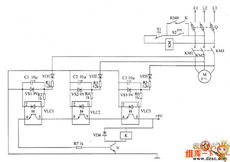
The motor protector circuit is composed of voltage detection circuit and protection control implementation circuit, the circuit is shown as the chart. Starting control circuit is composed of stop button S1, start button S2, AC contactor KM ( the original motor starting circuit). Voltage detection circuit is composed of the diodes VD1 ~ VD3, voltage regulator diodes VS1 ~ VS3, resistors R1 ~ R6, capacitors C1 ~ C3 and optocouplers VLC1 ~ VLC3. Protection control circuit consists of transistors V, relay K, diode VD4 and resistor R7. If one phase of the three-phase AC power is open-phase, the optocoupler in voltage detection circuit is turning off, V could not turn on, K does not pull in, disconnecting S2 will make KM released immediately to achieve fault phase automatic protection purpose. R1, R3 and R5 use 1 ~ 2W metal film resistors.
(View)
View full Circuit Diagram | Comments | Reading(1366)
Motor protector circuit diagram 11
Published:2011/5/21 10:28:00 Author:Lucas | Keyword: motor protector
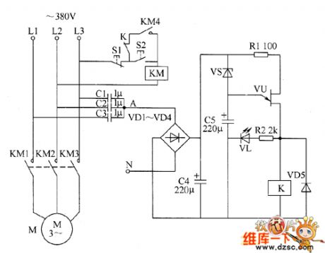
The motor protector circuit consists of capacitors C1 ~ C5, diodes VD1 ~ VD5, resistors R1, R2, zener diode VS, light-emitting diode VL, single-junction transistor VU and relay K, the circuit is shown as the chart. When the three-phase supply of L1 ~ L3 is in the normal, the junction point A on capacitors C1 ~ C3 has the lower AC voltage, the voltage is rectified by the VD1 ~ VD4, filtered by C4, so it is insufficient to turn on VS and VU, k does not pull in, the motor M operates normally. When the three-phase power is restored to normal, after a short delay VU deadline, K releases, then people can press the start button to restart the motor S2. R1 and R2 use 1/4W carbon film resistors or metal film resistors. C1 ~ C3 select CBB capacitors with the voltage being more than 400V: C4 and C5 select electrolytic capacitors, the withstand voltage of C4 is 25V, the withstand voltage of C5 is 16V. VD1 ~ VD5 use 1N4007 silicon rectifier diodes.
(View)
View full Circuit Diagram | Comments | Reading(741)
| Pages:9/12 123456789101112 |
Circuit Categories
power supply circuit
Amplifier Circuit
Basic Circuit
LED and Light Circuit
Sensor Circuit
Signal Processing
Electrical Equipment Circuit
Control Circuit
Remote Control Circuit
A/D-D/A Converter Circuit
Audio Circuit
Measuring and Test Circuit
Communication Circuit
Computer-Related Circuit
555 Circuit
Automotive Circuit
Repairing Circuit