
Index 301
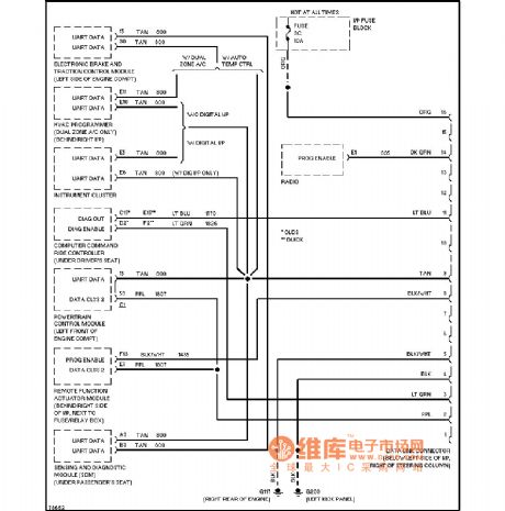
Buick computer dataline diagram
Published:2011/4/7 3:27:00 Author:Jessie | Keyword: computer dataline
View full Circuit Diagram | Comments | Reading(602)
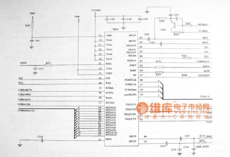
Nokia 8110 mobile maintenance circuit diagram
Published:2011/4/7 3:23:00 Author:Jessie | Keyword: mobile maintenance
View full Circuit Diagram | Comments | Reading(1042)
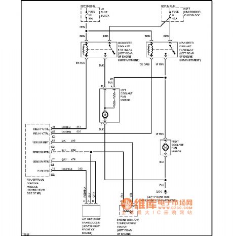
Buick air conditioning fan circuit diagram
Published:2011/4/7 3:22:00 Author:Jessie | Keyword: air conditioning fan
View full Circuit Diagram | Comments | Reading(870)
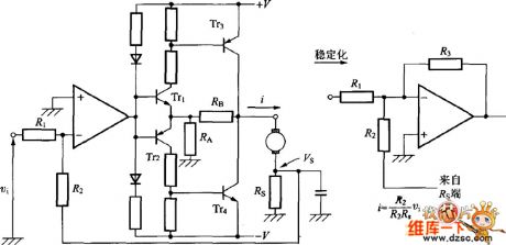
Drive circuit (voltage-type)
Published:2011/3/24 22:24:00 Author:muriel | Keyword: Drive circuit , voltage-type
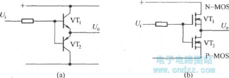
(a)as shown the drive circuit suitable for low frequency miniwatt drive, when the control signal Ui is high level, VT1 breakover, output voltage Uo corresponding control switch tube (IGBT) is breakover; When the control signal Ui is low level, VT2 breakover, output voltage Uo corresponding control switch tube (IGBT) be turn off.
(b) the drive circuit is shown by mosfet composition push-pull circuit, its working principle as figure (a) shows circuit. This circuit of high frequency peak value drive current can reach l0A above, it is suitable for high-power IGBT devices. (View)
View full Circuit Diagram | Comments | Reading(555)
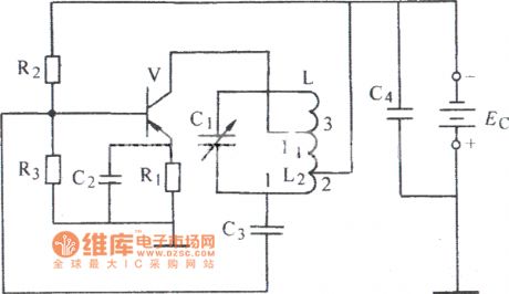
Improved common base inductance feedback oscillation circuit diagram
Published:2011/4/7 3:00:00 Author:Jessie | Keyword: Improved common base, inductance feedback oscillation

View full Circuit Diagram | Comments | Reading(523)
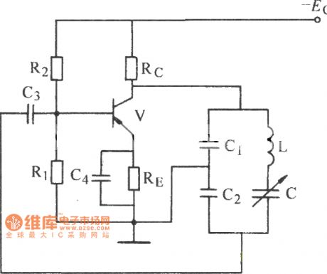
Improved capacitance feedback oscillating circuit diagram
Published:2011/4/7 3:03:00 Author:Jessie | Keyword: Improved capacitance, feedback oscillating
View full Circuit Diagram | Comments | Reading(525)
Capacitance feedback oscillating circuit diagram
Published:2011/4/7 2:53:00 Author:Jessie | Keyword: Capacitance feedback oscillating
View full Circuit Diagram | Comments | Reading(471)
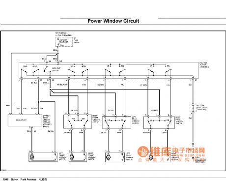
Buick power window circuit
Published:2011/4/7 2:51:00 Author:Jessie | Keyword: power window
View full Circuit Diagram | Comments | Reading(2006)
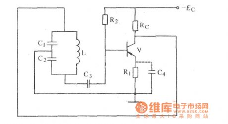
Inductance feedback oscillation circuit diagram
Published:2011/4/7 2:49:00 Author:Jessie | Keyword: Inductance feedback oscillation
View full Circuit Diagram | Comments | Reading(679)
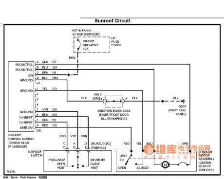
Buick sunroof circuit diagram
Published:2011/4/7 2:42:00 Author:Jessie | Keyword: sunroof
View full Circuit Diagram | Comments | Reading(977)
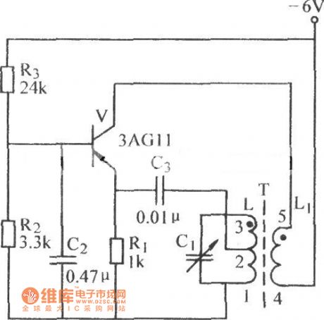
Common base transformer feedback oscillation circuit diagram
Published:2011/4/7 2:23:00 Author:Jessie | Keyword: Common base transformer, feedback oscillation
View full Circuit Diagram | Comments | Reading(687)
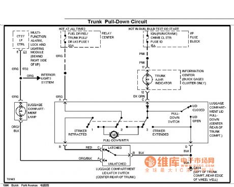
Buick baggage closing circuit
Published:2011/4/7 2:17:00 Author:Jessie | Keyword: baggage closing
View full Circuit Diagram | Comments | Reading(524)
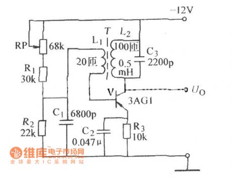
Transformer feedback oscillation circuit diagram
Published:2011/4/7 2:13:00 Author:Jessie | Keyword: Transformer feedback oscillation
View full Circuit Diagram | Comments | Reading(560)
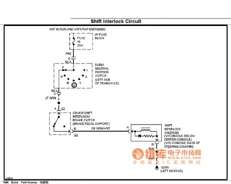
Buick shift interlocking circuit diagram
Published:2011/4/7 1:58:00 Author:Jessie | Keyword: shift interlocking
View full Circuit Diagram | Comments | Reading(614)
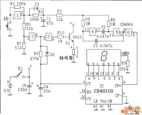
Intelligent alarm system audio circuit diagram
Published:2011/3/31 22:31:00 Author:Rebekka | Keyword: Intelligent alarm system, audio circuit
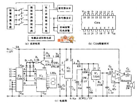
The alarm system will shows the floor and the room number of the steal and uses sound-light alarm. The block diagram of the system is shown in figure A. The sensor of the system uses Pyroelectric infrared control module. The power supply uses AC and DC automatically converted power supply. The audio alarm circuit of the system is shown in figure C. It is specially designed for the system. The Address matrix control circuit shown in figure A uses 2 manual button data transmission integrated circuits C306(shown in figure B). It has 11~19 input terminals and 4 output terminals, A, B, C, D. Usually, connecting 11~19 input terminals to ground potential through resistance. The output terminals ABCD are 0000 . When a steal happens, one input terminal will be at a high potential. If the terminal 13 is at a high potential, the output BCD code is 0011 . The decimal number is 3 . The matrix display(shown the floor and room number) panel is composed of 2 C403 and routing matrix. Figure C is an audio alarm circuit. It is composed of a C403 A, B, C output terminals. When a steal happens, one of the 11~14 output terminals will turn to a high potencial. One of the A, B, C terminals will turn to a high potencial. The gate circuit will enable VT1 saturate and turn on. The negative pulse transition of integrated electrodes will make monostable trigger circuit IC3 turn to a high potencial output. It will offer a working circuit for IC4.
(View)
View full Circuit Diagram | Comments | Reading(888)
Transistor current control circuit diagram
Published:2011/3/31 22:52:00 Author:Rebekka | Keyword: Transistor current control
Transistor current control circuit diagram is shown as below.
(View)
View full Circuit Diagram | Comments | Reading(1705)
DC voltage regulation circuit diagram
Published:2011/4/1 0:53:00 Author:Rebekka | Keyword: DC voltage regulation
DC voltage regulation circuit diagram is shown as below.
(View)
View full Circuit Diagram | Comments | Reading(771)
Using black and white TV as display terminal interface circuit diagram
Published:2011/4/1 2:51:00 Author:Rebekka | Keyword: display terminal interface
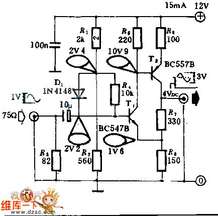
The interface circuit is added between computer standard video signal output terminal and TV. It can enlarge standard 1V(Peak - peak) video signal am to 3V(Peak - peak). Negative feedback circuit is composed of T1 and T2. It has a wide frequency range. The enlarge time is decided by the ratio of R1 and R2.
(View)
View full Circuit Diagram | Comments | Reading(1906)
Variable speed pick machine circuit diagram
Published:2011/4/1 1:03:00 Author:Rebekka | Keyword: Variable speed pick machine
Variable speed pick machine circuit diagram is shown as below.
(View)
View full Circuit Diagram | Comments | Reading(734)
Uncontrollable dual voltage circuit diagram
Published:2011/4/1 1:01:00 Author:Rebekka | Keyword: Uncontrollable dual voltage
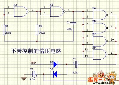
Uncontrollable dual voltage circuit diagram is shown as below.
(View)
View full Circuit Diagram | Comments | Reading(567)
| Pages:301/312 At 20301302303304305306307308309310311312 |
Circuit Categories
power supply circuit
Amplifier Circuit
Basic Circuit
LED and Light Circuit
Sensor Circuit
Signal Processing
Electrical Equipment Circuit
Control Circuit
Remote Control Circuit
A/D-D/A Converter Circuit
Audio Circuit
Measuring and Test Circuit
Communication Circuit
Computer-Related Circuit
555 Circuit
Automotive Circuit
Repairing Circuit