
Circuit Diagram
Index 1372
JFET_CHOPPER_CIRCUIT
Published:2009/6/23 2:14:00 Author:May
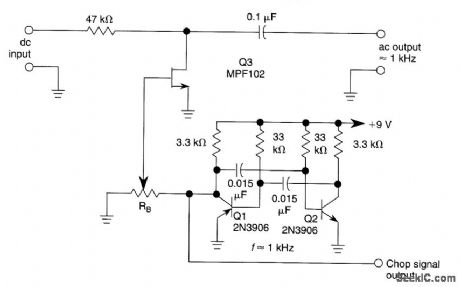
A JFET (MPF102) is used to chop a dc signal for amplification in an ac coupled amplifien Q3 is the chopper element and Q1-Q2 forms the multivibrator to derive a chopping signal. R, sets the bias on the FET to keep the drive to MPF102 as low as possible. (View)
View full Circuit Diagram | Comments | Reading(2347)
Photosensitive anti-theft alarm circuit diagram
Published:2011/5/17 3:36:00 Author:Ecco | Keyword: Photosensitive , anti-theft, alarm
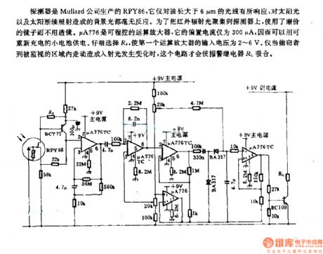
Detector is PRY86 produced by Mullard PRY86, it only responses to wavelengths whcih is greater than 6μm, and it has no reaction on background light caused by continued exposure of sunlight. In order to gather infrared light onto the detector, the inexpensive mirrors replace lenses. μA776 is a programmable operational amplifier, and its bias current is only 300μA, which can be recharged by a small battery. Careful selection of Ra could make the the input voltage of the first operational amplifier be 2 ~ 6V. Only if when the theft walksin the area being monitoredandit will causethe changing of incident light, then this circuit will make the alarm relay RL pull in.
(View)
View full Circuit Diagram | Comments | Reading(864)
SWITCHING_POWER_AMPLIFIER
Published:2009/6/23 2:14:00 Author:May
View full Circuit Diagram | Comments | Reading(809)
BEAT_FREQUENCY_OSCILLATOR_FOR_AM/SW_RADIOS
Published:2009/6/23 2:14:00 Author:May
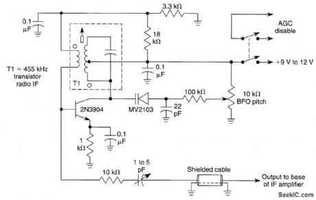
This BFO can be added to inexpensive AM/SW receivers to enable reception of CW signals. Output couples to base of last IF stage. T1 is any 455-kHz IF transformer. The BFO switch should be a DPDT type (as needed), and the radio AGC circuit will probably have to be disabled for CW reception. (View)
View full Circuit Diagram | Comments | Reading(1585)
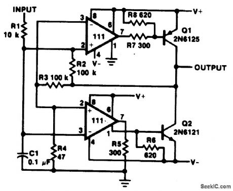
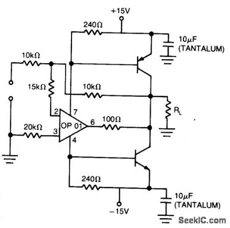
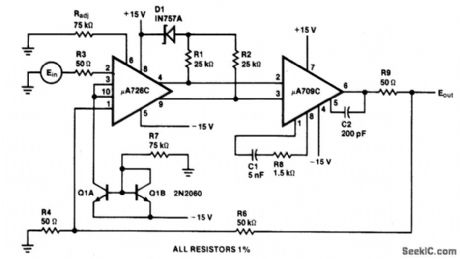
PRECISION_POWER_BOOSTER
Published:2009/6/23 2:13:00 Author:May
View full Circuit Diagram | Comments | Reading(778)
INVERTING_AMPLIFIER__WITH_BALANCING_CIRCUIT_
Published:2009/6/23 2:13:00 Author:May
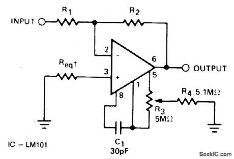
Req may be zero or equal to parallel combination of R1 and R2 for minimum offset. (View)
View full Circuit Diagram | Comments | Reading(698)
HYDROPHONE
Published:2009/6/23 2:13:00 Author:May
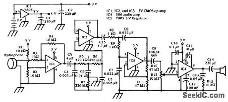
A commercially available hydrophone transducer is used in this system. The transducer is con-nected via a cable to the amplifier, which remains out of the water. The hydrophone should be suitably mounted for intended application. (View)
View full Circuit Diagram | Comments | Reading(3142)
REMOTE_OSCILLATOR_HIGH_FREQUENCY_VFO
Published:2009/6/23 2:12:00 Author:May
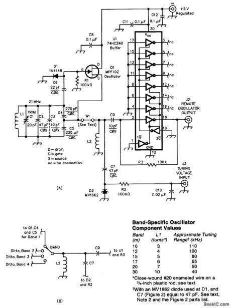


A remote VFO is sometimes used to control a transmitter or receiver. The circuit shown uses an MPF102 FET and is conyolled by a dc voltageat J3. The table shows values for L1 for various bands from 30 to 10 meters. U1 senres as a buffer amplifier. (View)
View full Circuit Diagram | Comments | Reading(1073)
Infrared anti-theft alarm circuit diagram
Published:2011/5/17 3:44:00 Author:Ecco | Keyword: Infrared, anti-theft , alarm circuit
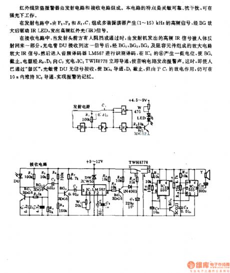
Infrared anti-theft alarm is composed of the radiating circuit and receiving circuit. This circuit is sensitive and reliable, anti-interference, it can work in bright light.
In radiating circuit, the multivibrator composed of F1, F2, and R1, C1 can produce 1 ~ 15KHz high frequency signal. After amplified by the BG, itdrives IR LED,emits a high-frequency infrared light (IR) signal.
In the receiving circuit, when there's someone passing or stopping in front of the launch head, the part of high-frequency IR signal from the transmitter will be reflected back by boby. DU photocell receives the signal, then it is amplifiered by the amplifier circuit composed of BG1, BG2, BG3 and RC components. And then it is decoded by the audio decoder LM567 and it produces low level on pin 8 of IC1 to stop BG1. Power charges for C1 by R1D1, ICdTWH8778 isimmediately turned onto make an alarm sound. At this time, even if the person has passed the restricted area , photodiode DU has no turn signal reception to make BG4, D1 cut off.
(View)
View full Circuit Diagram | Comments | Reading(1036)
SIMPLE_EXTERNAL_MICROPHONE_CIRCUIT_FOR_TRANSCEIVERS
Published:2009/6/23 2:11:00 Author:May
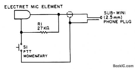
Used originally for an Icom ICZAT handie talkie, this circuit might prove useful in other applications. (View)
View full Circuit Diagram | Comments | Reading(967)
BASIC_LATCH_CIRCUITS
Published:2009/6/23 2:30:00 Author:Jessie
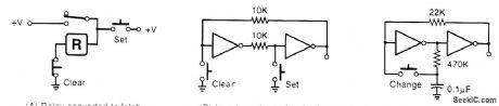
Some simple latches and alternate action circuits. (View)
View full Circuit Diagram | Comments | Reading(723)
NE602_OUTPUT_CIRCUITS
Published:2009/6/23 2:28:00 Author:Jessie
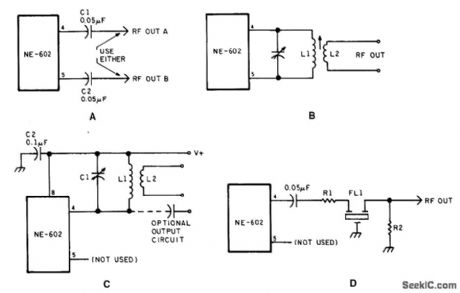
Output circuits for the NE-602. (View)
View full Circuit Diagram | Comments | Reading(723)
NE602_INPUT_CIRCUITS
Published:2009/6/23 2:27:00 Author:Jessie
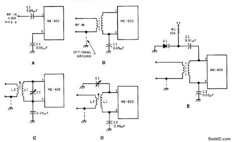
Input circuits for the NE-602. (View)
View full Circuit Diagram | Comments | Reading(1601)
TUNABLE_UHF_OSCILLATOR
Published:2009/6/23 2:27:00 Author:Jessie
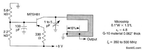
This oscillator is typical for 350- to 500-MHz operation. The microstrip inductor is a PC board trace. The tap is typically 15% from the bottom end. The output power is 55 to 100 mW into 50 Ω, with the frequency stability typically 0.1% over 0 to 50℃. (View)
View full Circuit Diagram | Comments | Reading(3095)
FM_HF_OSCILLATOR_WITH_NO_VARACTOR
Published:2009/6/23 2:25:00 Author:Jessie
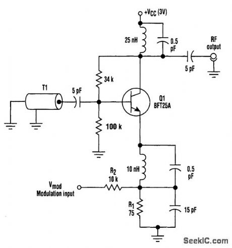
Instead of using a varactor to frequency-modulate a high-frequency oscillator, this circuit uses base-charging capacitance modulation. Consequently, the large voltage change required by a varactor, which can be a major problem in battery-powered systems with limited supply voltages, is elimtnated. T1 is a ceramic coaxial quarter-wave resonator. (View)
View full Circuit Diagram | Comments | Reading(1085)
×1000_AMPLIFIER_CIRCUIT
Published:2009/6/23 2:11:00 Author:May
View full Circuit Diagram | Comments | Reading(615)
AMPLIFIER_COOL_DOWN_CIRCUIT_I
Published:2009/6/23 2:25:00 Author:Jessie
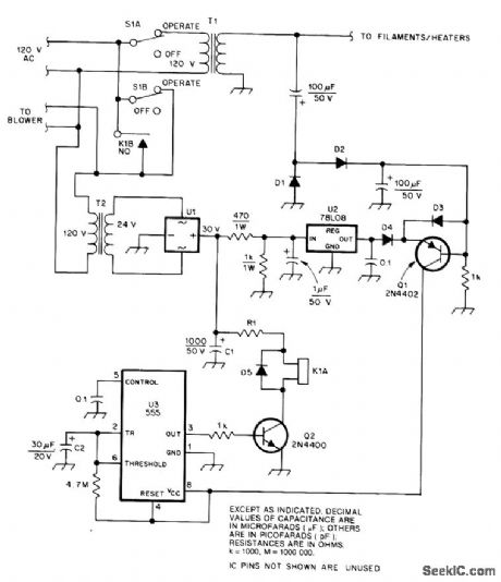
This cool-down relay circuit uses an IC timer to drive a relay, which keeps the blower on for a time delay from timer U3. The value of C2 can be changed to lengthen or shorten the time, as needed. (View)
View full Circuit Diagram | Comments | Reading(1473)
500_ksps_8_CHANNEL_DATA_DCQUISITION_CIRCUT
Published:2009/6/23 2:10:00 Author:May
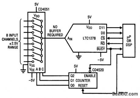
The high input impedance of the LTC1278 allows multiplexing without abuffer amplifier. Both sin-gle channel and multiplexed high-speed data acquisition systems benefit from the LTC1278/LTC1279's dynamic conversion performance. The 1.6-μs and 1.4-μs conversion and 200-ns and 180-ns S/H acquisition times enable the LTC1278/LTC1279 to convert a 500 ksps and 600 ksps, respectively. The figure shows a 500-ksps 8-channel data acquisition system. The LTC1278's high input impedance eliminates the need for a buffer amplifier between the multiplexer's output and the Adc's input. (View)
View full Circuit Diagram | Comments | Reading(0)
SIMPLE_PSEUDORANDOM_VOLTAGE_SOURCE
Published:2009/6/23 2:24:00 Author:Jessie
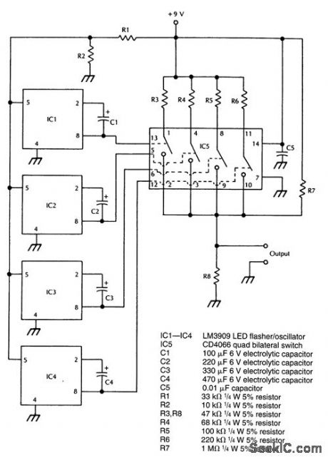
An approximation to a pseudorandom voltage is produced by combining the outputs of four low-frequency oscillators with 0.3, 0.6, 0.9, and 1.4 Hz frequencies. The summing network is a quad bilateral switch and resistor network. (View)
View full Circuit Diagram | Comments | Reading(735)
DARLINGTON_TRANSISTOR_OSCILLATOR
Published:2009/6/23 2:23:00 Author:Jessie
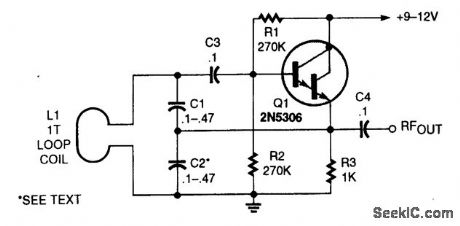
This oscillator uses a very large capacitance-to-inductance ratio. L1 is a one-tum coil consisting of a loop of #12 wire 12 in diameter. This circuit is useful for metal detectors, etc., where a loop antenna is used. (View)
View full Circuit Diagram | Comments | Reading(5010)
| Pages:1372/2234 At 2013611362136313641365136613671368136913701371137213731374137513761377137813791380Under 20 |
Circuit Categories
power supply circuit
Amplifier Circuit
Basic Circuit
LED and Light Circuit
Sensor Circuit
Signal Processing
Electrical Equipment Circuit
Control Circuit
Remote Control Circuit
A/D-D/A Converter Circuit
Audio Circuit
Measuring and Test Circuit
Communication Circuit
Computer-Related Circuit
555 Circuit
Automotive Circuit
Repairing Circuit