
Measuring and Test Circuit
Index 101
Composed of RD627 microwave alarm circuit diagram
Published:2011/3/31 2:39:00 Author:Rebekka | Keyword: microwave alarm
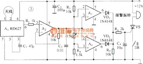
RD627 is a kind of sensor that uses doppler effect principle. It can convert moving objects displacement signals into corresponding signals. It can be widely used in automatic lights, automatic doors, moving objects counter, automatic switches and burglar alarm and other devices. Composed of RD627 microwave alarm circuit diagram is shown as below.
(View)
View full Circuit Diagram | Comments | Reading(1416)
Hospital beds pager circuit diagram
Published:2011/3/30 22:42:00 Author:Rebekka | Keyword: Hospital beds pager
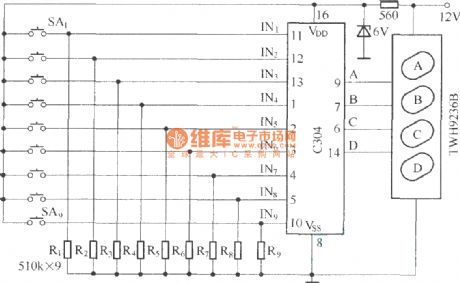
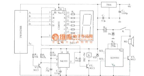
Call sound circuit is made up of voice circuit KD9561. Its sound is controlled by control circuit. When the receiver circuit receives the decoded valid. Io outputs a positive pulse. The pulse pull the relay K through control circuit. It sounds by connecting to the power KD9561.
(View)
View full Circuit Diagram | Comments | Reading(2047)
Infant sleep monitor
Published:2011/3/28 3:17:00 Author:Ecco | Keyword: Infant sleep monitors
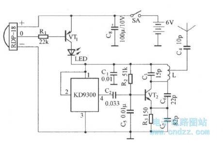
This circuit is composed of power switch circuit controlled by pyroelectric infrared detection module , analog music generating circuit and FM radio emission circuit component. (View)
View full Circuit Diagram | Comments | Reading(714)
Microampere meter internal resistance test circuit diagram
Published:2011/3/30 21:22:00 Author:Ecco | Keyword: microampere meter, internal resistance
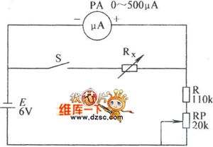
Microampere meter internal resistance test circuit diagram internal resistance test circuit diagram is as below:
(View)
View full Circuit Diagram | Comments | Reading(1284)
Internal resistance of power source measuring and test circuit diagram
Published:2011/3/20 22:56:00 Author:Ecco | Keyword: Internal resistance, power source
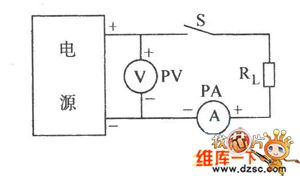
Internal resistance of power source measuring and test circuit diagram is as below:
(View)
View full Circuit Diagram | Comments | Reading(710)
18V Monitoring circuit diagram
Published:2011/3/24 20:10:00 Author:Ecco | Keyword: Monitoring circuit
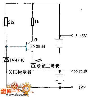
When ±18 V battery is discharged but cut to reserved low voltage, the Zener diode will be out of control, Q1's becoming is being positive-skew state, and the light-emitted diode needs to replace battery or refresh to them at this time. When the voltage of battery is normal, the Zener diode is placed in back bias state, the Q1 closes, and the light-emitted diode doesn't work and only consumes the current less than 1 mA. (View)
View full Circuit Diagram | Comments | Reading(878)
Low level capacitor measuring circuit diagram
Published:2011/3/22 1:00:00 Author:Ecco | Keyword: Low level capacitor
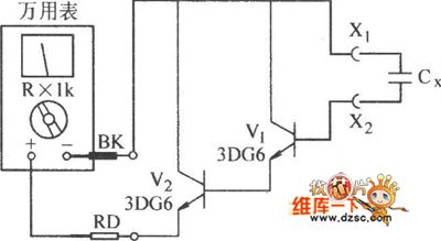
Low level capacitor measuring circuit diagram is as below:
(View)
View full Circuit Diagram | Comments | Reading(739)
The overpowering protective circuit diagram with the direct current and current measuring system MAX4211
Published:2011/3/22 21:14:00 Author:Ecco | Keyword: The overpowering protective circuit, direct current, current measuring system
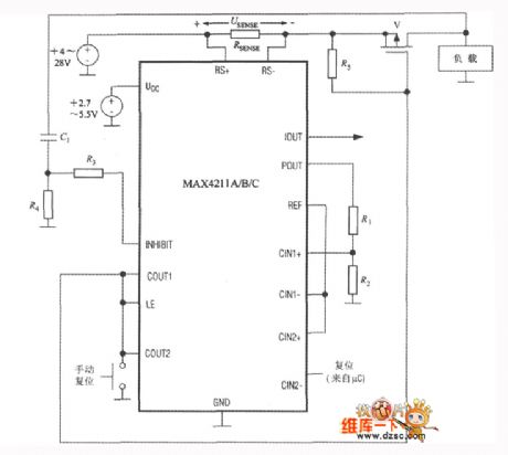
The overpowering protective circuit with MAX4211 is as below. The working principle is that the protective circuit will cut off the load current when checking out the overpowering error. The circuit can avoid the batteries from the damage of overpower of short circuit. Once it check out the overpowering error, the circuit will cut off P channel MOSFET(V) until pressing the reseting button. Simultaneously, the input power will make LE pin be in low level, and the output 1 of comparator 1 won't be locked, and the protective circuit will reset. When the characteristic of load changing, the load may produce surging current and higher voltage on POUT to cause malfunction. To avoid the circumstance, the circuit could connect a RC network(R4 and C1), and it can provide high level to INHIBIT port of comparator 1. In the term, the comparator 1 wil stop working, and the time of pause is decided by the formula that showing as below: t=R4C1ln(△U/0.6)。 In the formula, △U is variance of load voltage. The RC net will not produce an effect on the protection of long time overpowering circuit. R3 is resistance of the current limiter in 10kΩ. Follow the above-mentioned circuitry, it can be used as measuring the error of current, the exact method is connecting the resistance divider R1~R2 to IOUT port.
(View)
View full Circuit Diagram | Comments | Reading(673)
LMl35 precision temperature measurement circuit
Published:2011/3/21 1:13:00 Author:Joan | Keyword: precision , temperature measurement
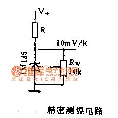
LMl35 series has equipped with outside correct terminal, which can easily correct measurement error and effectively eliminate the error caused by manufacturing process by simple correction method. As shown in Figure 4, when the temperature is 25 ℃, the adjustment potentiometer Rw changes the calibration terminal bias, until the sensor output voltage turns to 2.982V measured by a digital voltmeter in 20V output range. After calibration, the circuit's measurement error is less than 1 ℃ within the 0 to100C ℃ range. (View)
View full Circuit Diagram | Comments | Reading(680)
LM135 Basic temperature measurement circuit
Published:2011/3/18 1:26:00 Author:Joan | Keyword: temperature measurement
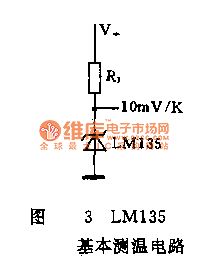
LM135 Basic temperature measurement circuit (View)
View full Circuit Diagram | Comments | Reading(1186)
| Pages:101/101 At 20101 |
Circuit Categories
power supply circuit
Amplifier Circuit
Basic Circuit
LED and Light Circuit
Sensor Circuit
Signal Processing
Electrical Equipment Circuit
Control Circuit
Remote Control Circuit
A/D-D/A Converter Circuit
Audio Circuit
Measuring and Test Circuit
Communication Circuit
Computer-Related Circuit
555 Circuit
Automotive Circuit
Repairing Circuit