
Measuring and Test Circuit
Index
Infra-red Level Detectors
Published:2013/7/30 20:12:00 Author:muriel | Keyword: Infra-red Level Detectors
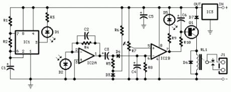
Parts:R1 10K 1/4W ResistorR2,R5,R6,R9 1K 1/4W ResistorsR3 33R 1/4W ResistorR4,R8 1M 1/4W ResistorsR7 10K Trimmer CermetR10 22K 1/4W ResistorC1,C4 1µF 63V Electrolytic or Polyester CapacitorsC2 47pF 63V Ceramic CapacitorC3,C5,C6 100µF 25V Electrolytic CapacitorsD1 Infra-red LEDD2 Infra-red Photo Diode (see Notes)D3,D4 1N4148 75V 150mA DiodeD5 LED (Any color and size)D6,D7 1N4002 100V 1A DiodesQ1 BC327 45V 800mA PNP TransistorIC1 555 Timer ICIC2 LM358 Low Power Dual Op-ampIC3 7812 12V 1A Positive voltage regulator ICRL1 Relay with SPDT 2A @ 220V switchCoil Voltage 12V. Coil resistance 200-300 OhmJ1 Two ways output socketDevice purpose:This circuit is useful in liquids level or proximity detection. It operates detecting the distance from the target by reflection of an infra-red beam. It can safely detect the level of a liquid in a tank without any contact with the liquid itself. The device's range can be set from a couple of cm. to about 50 cm. by means of a trimmer.Range can vary, depending on infra-red transmitting and receiving LEDs used and is mostly affected by the color of the reflecting surface. Black surfaces lower greatly the device's sensitivity.
Circuit operation:IC1 forms an oscillator driving the infra-red LED by means of 0.8mSec. pulses at 120Hz frequency and about 300mA peak current. D1 & D2 are placed facing the target on the same line, a couple of centimeters apart, on a short breadboard strip. D2 picks-up the infra-red beam generated by D1 and reflected by the surface placed in front of it. The signal is amplified by IC2A and peak detected by D4 & C4. Diode D3, with R5 & R6, compensate for the forward diode drop of D4. A DC voltage proportional to the distance of the reflecting object and D1 & D2 feeds the inverting input of the voltage comparator IC2B. This comparator switches on and off the LED and the optional relay via Q1, comparing its input voltage to the reference voltage at its non-inverting input set by the Trimmer R7.
Notes:Power supply must be regulated (hence the use of IC3) for precise reference voltages. The circuit can be fed by a commercial wall plug-in power supply, having a DC output voltage in the range 12-24V.Current drawing: LED off 40mA; LED and Relay on 70mA @ 12V DC supply.R10, C6, Q1, D6, D7, RL1 and J1 can be omitted if relay operation is not required.The infra-red Photo Diode D2, should be of the type incorporating an optical sunlight filter: these components appear in black plastic cases. Some of them resemble TO92 transistors: in this case, please note that the sensitive surface is the curved, not the flat one.Avoid sun or artificial light hitting directly D1 & D2.Usually D1-D2 optimum distance lies in the range 1.5-3 cm. (View)
View full Circuit Diagram | Comments | Reading(3290)
Air Flow Detectors
Published:2013/7/29 20:18:00 Author:muriel | Keyword: Air Flow Detectors
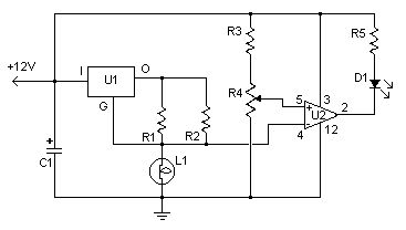
This simple circuit uses an incandescent lamp to detect airflow. With the filament exposed to air, a constant current source is used to slightly heat the filament. As it is heated, the resistance increases. As air flows over the filament it cools down, thus lowering it's resistance. A comparator is used to detect this difference and light an LED. With a few changes, the circuit can be connected to a meter or ADC to provide an estimation on the amount of air flow.
Parts:R1 100 Ohm 1/4W ResistorR2 470 Ohm 1/4W ResistorR3 10k 1/4W ResistorR4 100K 1/4W ResistorR5 1K 1/4W ResistorC1 47uF Electrolytic CapacitorU1 78L05 Voltage RegulatorU2 LM339 Op AmpL1 #47 Incandescent lamp with glass removed (See Notes )D1 LEDMISC Board, Wire, Sockets for ICs, etc.
Notes:1. The glass will have to be removed from L1 without breaking the filament. Wrap the glass in masking tape and it in a vise. Slowly crank down until the glass breaks, then remove the bulb and carefully peel back the tape. If the filament has broken, you will need another lamp. (View)
View full Circuit Diagram | Comments | Reading(3529)
Salt Taster
Published:2013/7/29 20:12:00 Author:muriel | Keyword: Salt Taster

Parts:R1 470R 1/4W ResistorR2,R5 10K 1/4W ResistorsR3,R6 220K 1/4W ResistorsR4 5K 1/2W Trimmer CermetR7 680R 1/4W ResistorR8 2K2 1/4W ResistorR9,R10,R11,R12,R13 1K 1/4W ResistorsC1 100µF 25V Electrolytic CapacitorD1,D2,D3 3 or 5mm. Red LEDsD4 3 or 5mm. Green LEDD5 3 or 5mm. Yellow LEDIC1 LM324 Low Power Quad Op-ampP1 SPST PushbuttonProbes (See Text)B1 9V PP3 BatteryClip for PP3 Battery
Device purpose:This circuit was designed to detect the approximate percentage of salt contained in a liquid. After careful setting it can be useful to persons needing a quick, rough indication of the salt content in liquid foods for diet purposes etc.
Circuit operation:IC1A op-amp is wired as a DC differential amplifier and its output voltage increases as the DC resistance measured at the probes decreases. In fact, fresh water has a relatively high DC resistance value that will decrease proportionally as an increasing amount of salt is added.IC1B, IC1C and IC1D are wired as comparators and drive D5, D4 and D3 in turn, as the voltage at their inverting inputs increase. Therefore, no LED will be on when the salt content of the liquid under test is very low, yellow LED D5 will illuminate when the salt content is low, green LED D4 will illuminate if the salt content is normal and red LED D3 will illuminate if the salt content is high.D1 and D2 are always on, as their purpose is to provide two reference voltages, thus improving circuit precision. At D2 anode a stable 3.2V supply feeds the non-inverting inputs of the comparators by means of the reference resistor chain R8, R9 and R10. The 1.6V reference voltage available at D1 anode feeds the probes and the set-up trimmer R4.One of these two red LEDs may be used as a pilot light to show when the device is on.
Probes:It was found by experiment that a good and cheap probe can be made using a 6.3mm. mono jack plug. The two plug leads are connected to the circuit input by means of a two-wire cable (a piece of screened cable works fine).The metal body of the jack is formed by two parts of different length, separated by a black plastic ring. You should try to cover the longest part with insulating tape in order to obtain an exposed metal surface of the same length of the tip part, i.e. about 8 to 10mm. starting from the black plastic ring.In the prototype, three tablespoons of liquid were poured into a cylindrical plastic cap of 55mm. height and 27mm. diameter, then the metal part of the jack probe was immersed in the liquid.
Notes:Wait at least 30 seconds to obtain a reliable reading.Wash and wipe carefully the probe after each test.To setup the circuit and to obtain a more precise reading, you may use a DC voltmeter in the 10V range connected across pin #1 of IC1A and negative supply.Set R4 to obtain a zero reading on the voltmeter when the probe is immersed in fresh water.You may change at will the threshold voltage levels at which the LEDs illuminate by trimming R4. Vary R8 value to change D4 range and R9 value to change D5 range.P1 pushbutton may be substituted by a common SPST switch. (View)
View full Circuit Diagram | Comments | Reading(0)
Infrared Detector
Published:2013/7/29 20:05:00 Author:muriel | Keyword: Infrared Detector

The infra red radiation is a region with bigger length of wave from the visible spectrum. It is a region which our eye does not conceive, the consequences however which we felt as heat of. The manufacture that to you we propose receives this region and on one side us notice with optical clue, otherwise we can observe the configuration of width of radiation.
The circuit of manufacture appears in form. sensory is a passage of silicon with relatively big surface. This passage when it is not litted up by infra red light has very big resistance of order of Mohm. this resistance is reversely proportional at approach of brightness. The type of passage is not critical, in the place can enter anyone. The resistance of passage him we use in order to polarize a transistor of npn type BC547. The photodiode enters between in the collector and in the base. The current that leak the passage is multiplied by the b of transistor and it is presented in the emitter of transistor. This current is enough in order to it leads and it turns on a Led . En line with this circuit exists a resistance in order to it limits his current.
The infra red radiation has very a lot of applications in the industry and in the trade. The more important perhaps application they are telecontrols, that exist everywhere. The proposed manufacture is based on a passage of silicon which is connected in amplifier. The exit of amplifier leads a Led. Each time where lights it means that hits infrared radiation in the sensor. The circuit allocates moreover a exit in that we can connect a small acoustic amplifier or even a oscilloscope.
In utmost this resistance is presented a tendency of proportional incident radiation. If in deed the radiation has been shaped at width then will be presented in utmost her component of configuration. If for example falls in the photodiode for some reason a fraction of beam from infrared laser with configuration by sound then in utmost the resistance will be presented wave the sound. In this point we added a exit for oscilloscope for a small amplifier. The tendency of catering should have noise and be clean. Stabilised power supply it ensures this operation. The stabilisation becomes with stabilizer of tendency 7808.
In order to you make the manufacture you will need printed that exists in what form , in you will place the materials according to form. At the placement it should you give few attention in the right time of semiconductors, transistors passages and stabilizer of tendency. In the circuit of emitter Q2 it exists a led, which it will turn on each time where incident infrared radiation in the photodiode. In the exit of Q1 you will find the same signal strengthened. This signal will contain the at width unmodulate information that will have the radiation (or this emanates from telecontrols, or from laser).
PartsR1 47K R2 220 R3 220K R4 1K R5 180 C1,2 220nFC3 10uFC4 22uF C5 100nFC6 100nFIC1 7812Q1 BC547Q2 BC547D1 LedD2 TIL81 (View)
View full Circuit Diagram | Comments | Reading(2455)
Light/Dark Detectors
Published:2013/7/28 20:14:00 Author:muriel | Keyword: Light/Dark Detectors
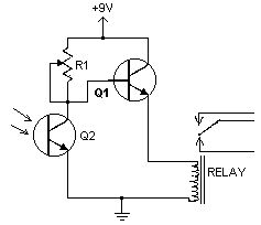
This handy little circuit can tell the difference between darkness and light, making it very useful for switching on and off signs, porch lights or other things when it gets dark or light.
Parts:R1 100K PotQ1 2N3904 NPN Transistor or 2N2222Q2 NPN PhototransistorRELAY 9V RelayMISC Board, Wire, 9V Battery Snap (if battery used), Knob For R1Notes:1. R1 Adjusts sensitivity (View)
View full Circuit Diagram | Comments | Reading(2704)
Rain Detector
Published:2013/7/28 20:10:00 Author:muriel | Keyword: Rain Detector
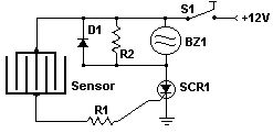
This circuit uses a sensor made of a small piece of etched PC board and a simple SCR circuit to detect rain and sound a buzzer. The SCR could also be used to activate a relay, turn on a lamp, or send a signal to a security system.
PartsR1 1K 1/4 W ResistorR2 680 Ohm 1/4 W ResistorD1 1N4001 Silicon DiodeBZ1 12V BuzzerS1 SPST SwitchSCR1 C106B1 SCR 106CYSENSOR See NotesMISC Board, Wire, Case, PC Board (For Sensor)
Notes1. The sensor is a small piece of PC board etched to the pattern showen in the schematic. The traces should be very close to each other, but never touching. A large spiral pattern would also work.2. Make sure to use a loud buzzer. (View)
View full Circuit Diagram | Comments | Reading(2408)
Room Noise Detectors
Published:2013/7/28 20:09:00 Author:muriel | Keyword: Room Noise Detectors
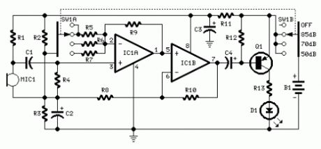
Parts:R1 10K 1/4W ResistorR2,R3 22K 1/4W ResistorsR4 100K 1/4W ResistorR5,R9,R10 56K 1/4W ResistorsR6 5K6 1/4W ResistorR7 560R 1/4W ResistorR8 2K2 1/4W ResistorR11 1K 1/4W ResistorR12 33K 1/4W ResistorR13 330R 1/4W ResistorC1 100nF 63V Polyester CapacitorC2 10µF 25V Electrolytic CapacitorC3 470µF 25V Electrolytic CapacitorC4 47µF 25V Electrolytic CapacitorD1 5mm. Red LEDIC1 LM358 Low Power Dual Op-ampQ1 BC327 45V 800mA PNP TransistorMIC1 Miniature electret microphoneSW1 2 poles 4 ways rotary switchB1 9V PP3 BatteryClip for PP3 Battery
Device purpose:This circuit is intended to signal through a flashing LED, the exceeding of a fixed threshold in room noise, chosen from three fixed levels, namely 50, 70 & 85 dB. Two Op-amps provide the necessary circuit gain for sounds picked-up by a miniature electret microphone to drive a LED. With SW1 in the first position the circuit is off. Second, third and fourth positions power the circuit and set the input sensitivity threshold to 85, 70 & 50 dB respectively.Current drawing is <1mA with LED off and 12-15mA when the LED is steady on.
Use:Place the small box containing the circuit in the room you intend to measure ambient noise.The 50 dB setting is provided to monitor the noise in the bedroom at night. If the LED is steady on, or flashes bright often, then your bedroom is inadequate and too noisy for sleep.The 70 dB setting is for living-rooms. If this level is often exceeded during the day, your apartment is rather uncomfortable.If noise level is constantly over 85 dB, 8 hours a day, then you live in a dangerous environment.
dB Example of sound sources20 Quiet garden, electric-clock ticking, drizzling rain30 Blast of wind, whisper @ 1 m.40 Countryside areas, quiet apartment, wrinkling paper @ 1 m.50 Residential areas, quiet streets, fridges, conversation @ 1 m.55 Offices, air-conditioners60 Alarm-clocks, radio & TV sets at normal volume64 Washing machines, quiet typewriters67 Hair-dryers, crowded restaurants69 Dish-washers, floor-polishers70 Loud conversation, noisy street, radio & TV sets at high volume72 Vacuum cleaners78 Telephone ring, mechanical workshop80 Passing trucks, noisy hall or plant, shuffling @ 1 m.90 Passing train, pneumatic hammer, car hooter @ 1 m.95 Mega disco , circular saw100 Motorcycle without silencer (View)
View full Circuit Diagram | Comments | Reading(2518)
PIC diode tester
Published:2013/7/28 19:59:00 Author:muriel | Keyword: PIC diode tester

View full Circuit Diagram | Comments | Reading(2846)
reliable car battery tester
Published:2013/7/25 20:59:00 Author:muriel | Keyword: car battery tester

This circuit uses the popular and easy to find LM3914 IC. This IC is very simple to drive, needs no voltage regulators (it has a built in voltage regulator) and can be powered from almost every source.
This circuit is very easy to explain:
When the test button is pressed, the Car battery voltage is feed into a high impedance voltage divider. His purpose is to divide 12V to 1,25V (or lower values to lower values). This solution is better than letting the internal voltage regulator set the 12V sample voltage to be feed into the internal voltage divider simply because it cannot regulate 12V when the voltage drops lower (linear regulators only step down). Simply wiring with no adjust, the regulator provides stable 1,25V which is fed into the precision internal resistor cascade to generate sample voltages for the internal comparators. Anyway the default setting let you to measure voltages between 8 and 12V but you can measure even from 0V to 12V setting the offset trimmer to 0 (but i think that under 9 volt your car would not start). There is a smoothing capacitor (4700uF 16V) it is used to adsorb EMF noise produced from the ignition coil if you are measuring the battery during the engine working. Diesel engines would not need it, but I'm not sure. If you like more a point graph rather than a bar graph simply disconnect pin 9 on the IC (MODE) from power. The calculations are simple (default)For the first comparator the voltage is : 0,833 V corresponding to 8 V* * * * * voltage is : 0,875 V corresponding to 8,4 Vfor the last comparator the voltage is : 1,25 V corresponding to 12 VHave fun, learn and don't let you car battery discharge... ;-) (View)
View full Circuit Diagram | Comments | Reading(4317)
Cut Phone Line Detector 1
Published:2013/7/25 20:53:00 Author:muriel | Keyword: Cut Phone Line, Detector
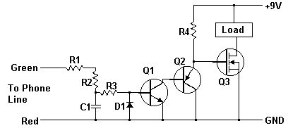
A while ago I got an email asking for the schematic of a circuit to detect cut phone lines. It didn't take me long to find this circuit in Electronics Now. When the circuit detects that a phone line has been cut, it activates a MOSFET which can be used to drive a relay, motor, etc. It can also be connected to a security system.
PartsR1, R2, R3 22 Meg 1/4 W ResistorR4 2.2 Meg 1/4 W ResistorC1 0.47uF 250V Mylar CapicitorQ1 2N3904 Transistor or 2N2222Q2 2N3906 TransistorQ3 IRF510 Power MOSFETD1 1N914 DiodeLoad See Notes MISC Wire, Phone Connectors, Circiut Board
Notes1. The Load can be a relay, lamp, motor, etc. The circuit can also be connected to a security system to sound an alarm in case the phone line is cut.2. If the circuit is connected to a security system or other circuit, both circuits must be electrically isolated from each other using an opto-isolator, relay, etc. This also means that the Cut Phone Line Detector must be powered by a seperate 9V supply. (View)
View full Circuit Diagram | Comments | Reading(2027)
Cellular Phone calling Detectors
Published:2013/7/24 20:42:00 Author:muriel | Keyword: Cellular Phone , calling Detectors
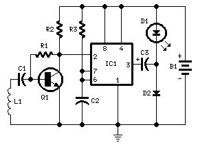
Parts:R1 100K 1/4W ResistorR2 3K9 1/4W ResistorR3 1M 1/4W ResistorC1,C2 100nF 63V Polyester CapacitorsC3 220µF 25V Electrolytic CapacitorD1 LED Red 10mm. Ultra-bright (see Notes)D2 1N5819 40V 1A Schottky-barrier Diode (see Notes)Q1 BC547 45V 100mA NPN TransistorIC1 7555 or TS555CN CMos Timer ICL1 Sensor coil (see Notes)B1 1.5V Battery (AA or AAA cell etc.)
Device purpose:This circuit was designed to detect when a call is incoming in a cellular phone (even when the calling tone of the device is switched-off) by means of a flashing LED.The device must be placed a few centimeters from the cellular phone, so its sensor coil L1 can detect the field emitted by the phone receiver during an incoming call.
Circuit operation:The signal detected by the sensor coil is amplified by transistor Q1 and drives the monostable input pin of IC1. The IC's output voltage is doubled by C2 & D2 in order to drive the high-efficiency ultra-bright LED at a suitable peak-voltage.
Notes:Stand-by current drawing is less than 200µA, therefore a power on/off switch is unnecessary.Sensitivity of this circuit depends on the sensor coil type.L1 can be made by winding 130 to 150 turns of 0.2 mm. enameled wire on a 5 cm. diameter former (e.g. a can). Remove the coil from the former and wind it with insulating tape, thus obtaining a stand-alone coil.A commercial 10mH miniature inductor, usually sold in the form of a tiny rectangular plastic box, can be used satisfactorily but with lower sensitivity.IC1 must be a CMos type: only these devices can safely operate at 1.5V supply or less.Any Schottky-barrier type diode can be used in place of the 1N5819: the BAT46 type is a very good choice.
(View)
View full Circuit Diagram | Comments | Reading(4921)
IR Remote Control Tester
Published:2013/7/24 20:40:00 Author:muriel | Keyword: IR , Remote Control, Tester
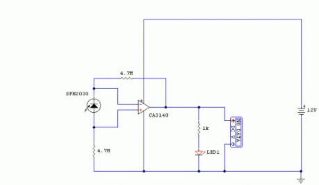
Notes:I have used a photodiode, SFH2030 as an infra red sensor. A MOSFET opamp, CA3140 is used in the differential mode to amplify the pulses of current from the photodiode. LED1 is an ordinary coloured led which will light when IR radiation is being received. The output of the opamp, pin 6 may be connected to a multimeter set to read DC volts. Infra red remote control strengths can be compared by the meter reading, the higher the reading, the stronger the infra red light. I aimed different remote control at the sensor from about 1 meter away when comparing results. For every microamp of current through the photodiode, about 1 volt is produced at the output. A 741 or LF351 will not work in this circuit. Although I have used a 12 volt power supply, a 9 volt battery will also work here. (View)
View full Circuit Diagram | Comments | Reading(2337)
XTal Tester
Published:2013/7/24 20:39:00 Author:muriel | Keyword: XTal Tester
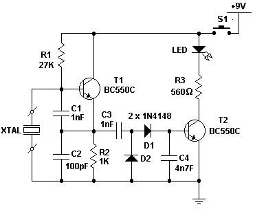
This is a simple XTal tester circuit. T1 and XTal have formed an oscillator. C1 and C2 are voltage divider for oscillator. if the XTal is safe, the oscillator will work well and its output voltage will be rectified by C3, C4, D1 and D2, then T2 will run and LED will light. The circuit is suitable to test 100KHz - 30MHz Xtal.
(View)
View full Circuit Diagram | Comments | Reading(8316)
Picoammeter circuit with 4 ranges
Published:2013/7/24 20:38:00 Author:muriel | Keyword: Picoammeter circuit, 4 ranges

This circuit uses a CA3420 BiMOS op amp to form a picoammeter with 4 ranges. The exceptionally low input current (typically 0.2pA) makes the CA3420 highly suited for use in a picoammeter circuit. Input transient protection is provided by the 1 megohm resistor in series with the input. The 10 megohm resistor connected to pin 2 decouples the potentially high input capacitance often associated with lower current circuits and reduces the tendency for the circuit to oscillate under these conditions. The 10k potentiometer is used for null offset.
(View)
View full Circuit Diagram | Comments | Reading(3248)
Field-strength meters
Published:2013/7/24 20:37:00 Author:muriel | Keyword: Field-strength meters
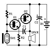
Parts:R1 330K 1/4W ResistorR2 100R 1/4W ResistorC1 10nF 63V Polyester or Ceramic CapacitorC2 100µF 25V Electrolytic CapacitorQ1 BC547 45V 100mA NPN TransistorQ2 BC327 45V 800mA PNP TransistorSW1 Reed Switch and small magnet (See Notes)SPKR 8 Ohm Loudspeaker (See Notes)B1 3V Battery (two A or AA cells wired in series etc.)
Device purpose:This circuit, enclosed in a small plastic box, can be placed into a bag or handbag. A small magnet is placed close to the reed switch and connected to the hand or the clothes of the person carrying the bag by means of a tiny cord.If the bag is snatched abruptly, the magnet looses its contact with the reed switch, SW1 opens, the circuit starts oscillating and the loudspeaker emits a loud alarm sound.The device can be reverse connected, i.e. the box can be placed in a pocket and the cord connected to the bag.This device can be very useful in signalling the opening of a door or window: place the box on the frame and the magnet on the movable part in a way that magnet and reed switch are very close when the door or window is closed.
Circuit operation:A complementary transistor-pair is wired as a high efficiency oscillator, directly driving a small loudspeaker. Low part-count and 3V battery supply enable a very compact construction.
Notes:The loudspeaker can be any type, its dimensions are limited only by the box that will contain it.An on-off switch is unnecessary because the stand-by current drawing is less than 20µA.Current consumption when the alarm is sounding is about 100mA.If the circuit is used as anti-bag-snatching, SW1 can be replaced by a 3.5mm mono Jack socket and the magnet by a 3.5mm. mono Jack plug with its internal leads shorted. The Jack plug will be connected with the tiny cord etc.Do not supply this circuit with voltages exceeding 4.5V: it will not work and Q2 could be damaged. In any case a 3V supply is the best compromise.
(View)
View full Circuit Diagram | Comments | Reading(0)
Latching Continuity Tester 1
Published:2013/7/24 20:35:00 Author:muriel | Keyword: Latching Continuity Tester

View full Circuit Diagram | Comments | Reading(3248)
Latching Continuity Tester
Published:2013/7/24 20:34:00 Author:muriel | Keyword: Latching Continuity Tester
This Latching Continuity Tester can help you locate those difficult-to-find intermittent short and opens that other testers always seem to miss. It has been part of my workbench for many years and performs superb. I have solved many intermittend problem with this highly flexible unit.
Latching Continuity TesterA continuity tester is a must on every service bench for testing cables, pcboards, switches, motors, plugs, jacks, relays, and many other kinds of components. But there are times when a simple continuity test doesn't tell the whole story. For example, vibration-induced problems in automobile wiring can be extremely difficult to detect because a short or open is not maintained long enough for a non-latching tester to respond.This latching continuity tester detects intermittent (and steady state) opens and shorts. The tester will detect and latch on an intermittent condition with a duration of less than a millisecond. In addition, it provides both visual and (defeatable) audio indicators, uses only one inexpensive and easy-to-find IC, and can be built from all new parts for about $35, or less if you have a well-stocked junkbox.
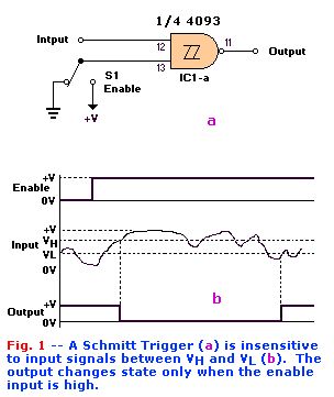
Circuit Elements:Schmitt Trigger The heart of the circuit is a 4093 quad tow-input NAND Schmitt trigger, one gate of which is shown in Fig. 1-a. The gate functions as shown in Fig. 1-b. Nothing happens until the enable input goes high. When that happens, the output responds to the input as follows.
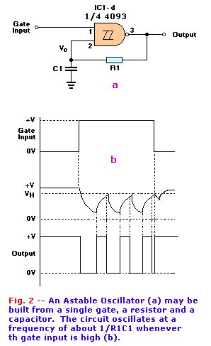
As long as the input voltage stays between VH and VL, the output stays high. But when the input goes above VH, the output goes low. The output will not go high again until the input goes below VL. That characteristic is what gives the Schmitt trigger its ability to square-up a slowly changing input signal. The Schmitt trigger is ideally suited for our application because it is not dependent on edge triggering, and because both slow and fast signals trigger it when either threshold is exceeded.We use two gates of the 4093 as a combination detector and latch. The gates are cross connected to form an SR (Set-Reset) flip-flop. When pin 12 goes low, pin 11 will go high. That high may be used to enable an LED or other indicator. Switch S1 is used to select whether the tester will provide ouput when it detects an open or a short. In the OPEN position, pin 12 is held low, so the output of the gate is normally high. When the test leads are connected across a short, pin 12 is pulled high, so the output drops low. The circuit works in the converse manner when S1 is in the CLOSED position.As shown in Fig. 2-a, we use another Schmitt trigger to build a gated astable oscillator. A gated astable oscillator produces output as long as the GATE input is high. Fig. 2-b shows the waveforms that are present at various points in the circuit. When the pin-8 input goes high, pin 10 goes low, and C1 starts discharging through R1. When VC falls below VL, the output of the gate goes high, so C1 starts charging through R1. When VC exceeds VH, the output again drops low. Oscillation continues in that way as long as the gate input remains high. The frequency of oscillation is given by a fairly complex equation that can be simplified, for purposes of approximation, as F = 1 / R1C1.
Putting it all together:The complete circuit is shown in Fig. 3. In that circuit, IC1-a and IC1-b funtion as the flip-flop/detector. The output of IC1-a is routed through S4, AUDIO. When that switch is closed, IC1-d is enabled and an audio tone will be output by BZ1. The frequency of that tone can vary from 1000Hz to well above the audio range (100KHz), according to the setting of R4. In addition, R4 varies frequency and volume simultaneously, so you can set it for the combination that pleases you best. Originally we used a PM (Permanent Magnet) speaker. Whe the detector has not been tripped, the full power-supply voltage is across the buzzer, but no current is drawn. The reason is that the piezo element is like a capacitor and does not conduct DC current. Whe the circuit is oscillating, the buzzer consumes a current of only about 0.5 milliamp. The output of the flip-flop/detector circuit also drives IC1-c. If S2 is in the AUTO position, the output of IC1-c will automatically reset the flip-flop after a period of two to six seconds, depending on the position of R7. If S2 is in the MANUAL position, the LED will remain lit (and the buzzer will continue buzzing, if S4 is on) until maual RESET switch S3 is pressed
Construction:Astable OscillatorThe circuit may be built on a piece of perforated construction board or Vero-board, or on a PCB. The PCB is designed to take board-mounted switches, which makes a neat package and eliminates a rat's nest.Referring to Fig. 4, mount and solder the components in this order: diodes, fixed resistors, IC-sockets, capacitors, variable resistors, and then the pcb mounted switches. The regular ones will work too it just means more wire. Mount the buzzer and the LED last as described below. Trimmer potentiometer R7 is manufactured by Piher (903 Feehanville Drive, Mount Prospect, IL 60056); it has a shaft that extends through the panel. If the Piher pot is unavailable, an alternate is available from Digi-Key (701 Brooks Ave, South, P.O. Box 677, Thief River Falls, MN 56701). The disadvantage of the alternate is that it has no shaft, so it must be adjusted using a miniature screwdriver.The circuit board is helf approximately 1/2-inch from the cover by the shafts of the switches. The LED and the buzzer should be inserted in the approproate holes in the pcb now. Then install the top cover, and adjust the height of the LEDso that it protrudes through the top cover. Then solder its leads. Attach the buzzer to the top cover, using silicone rubber adhesive (RTV or double side foam tape.We mounted a pair of banana jacks on the top of our prototype's case, but you could solder the wires directly to the appropriate points on the circuit board, tie strain reliefs in the wires, and then solder alligator clips to the ends of the wires. However, a set of good leads are really all that expensive and it does give the tester more flexible usage as you have the opportunity to use a variety of different leads to suit your purpose.
(View)
View full Circuit Diagram | Comments | Reading(2522)
Geomagnetic field detectors
Published:2013/7/24 20:30:00 Author:muriel | Keyword: Geomagnetic field detectors
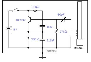
This basic oscillator will detect the Earth magnetic field. The ferrite rod and coil are taken from an old Medium Wave receiver and a small magnet is glued at one end. Tune to a medium wave commercial station until you hear a beat note. Any movement of the ferrite rod will produce an audible note that depends on the prevailing Earth magnetic field. Screening is essential. Use a plastic box padded, on the inside, with copper wires running parallel to the rod and grounded in one place only. A small hole is made in the box in order to adjust the trimmer capacitor with a plastic screwdriver. An American equivalent to the BC337 could be the 2N2369A but I did not try it out.
(View)
View full Circuit Diagram | Comments | Reading(3569)
Simple Servo Tester
Published:2013/7/24 20:29:00 Author:muriel | Keyword: Simple Servo Tester

This is a simple servo tester which will comprehensively test the capabilities of almost any modern servo. It has two pushbuttons, CENTRE and SWEEP and a potentiometer which works as follows:- CENTRE Does exactly that, centers the servo, afterwards the potentiometer determines position.- SWEEP Sweeps the servo back and forth at a rate determined by the potentiometer setting.The PIC uses its internal timer to set up a constant frame duration of 20ms and the on/off ratio is set by the user. (View)
View full Circuit Diagram | Comments | Reading(2561)
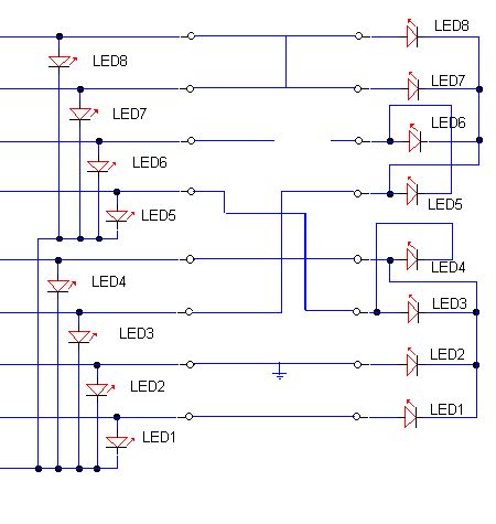
Multi Wire Cable Tester 2
Published:2013/7/24 20:27:00 Author:muriel | Keyword: Multi Wire , Cable Tester
View full Circuit Diagram | Comments | Reading(3839)
| Pages:1/101 1234567891011121314151617181920Under 20 |
Circuit Categories
power supply circuit
Amplifier Circuit
Basic Circuit
LED and Light Circuit
Sensor Circuit
Signal Processing
Electrical Equipment Circuit
Control Circuit
Remote Control Circuit
A/D-D/A Converter Circuit
Audio Circuit
Measuring and Test Circuit
Communication Circuit
Computer-Related Circuit
555 Circuit
Automotive Circuit
Repairing Circuit