
Measuring and Test Circuit
Index 21
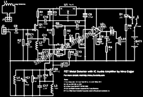
BFO Metal Detector using LF347N
Published:2012/9/13 21:14:00 Author:Ecco | Keyword: BFO Metal Detector

Here's a metal detector circuit that frequencies of the two oscillators are then mixed in similar fashion to BFO, to produce an audible heterodyne. On the surface of it, this design would seem to represent little more than a twinned BFO metal detector.
(View)
View full Circuit Diagram | Comments | Reading(4089)
Simple metal detector with 4011
Published:2012/9/13 21:14:00 Author:Ecco | Keyword: Simple metal detector
This simple metal detector requires only a handful of components and an evening's work. Built around a cmos4011 IC, is very robust and versatile. The 250 kHz reference oscillator is built with two gates (U1/1 and U1/2), C1, R1 and P1. The search oscillator uses only one gate (U1/3), two capacitors and the search coil. The outputs of the two oscillators are fed to the fourth gate acting as a mixer and filtered with C4. (View)
View full Circuit Diagram | Comments | Reading(1778)
Metal detector circuit with CS209A
Published:2012/9/13 21:13:00 Author:Ecco | Keyword: Metal detector
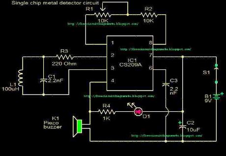
This circuit is a Single chip metal detector.Actually we can use this one to detect metals.Specially,I think you have seen some army soldiers keep some thing to detect metals.That equipment has been made through this circuit.so you also can use this to detect metals even bombs.
Source: NEXT.GR (View)
View full Circuit Diagram | Comments | Reading(3769)
Single transistor Metal Detector circuit
Published:2012/9/13 21:12:00 Author:Ecco | Keyword: Single transistor, Metal Detector
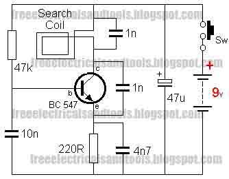
The circuit is an oscillator and the way it keeps oscillating is due to positive feedback. This is the case with all oscillators and the component that provides the feedback is the 1n capacitor between the collector and emitter of the transistor. It may seem unusual that the transistor can be turned on via the emitter to keep it oscillating, but in fact it does not matter if the emitter or base receives a signal as the important factor is THE VOLTAGE DIFFERENCE between these two terminals.
Source: NEXT.GR (View)
View full Circuit Diagram | Comments | Reading(2477)
Zero beating Metal Detector
Published:2012/9/13 21:11:00 Author:Ecco | Keyword: Zero beating, Metal Detector
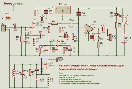
Both oscillators are built using MPF102 or J310 FETs. The Mixer is BF998 dual gate MOSFET. Audio IC amplifier is LM386 which drives a speaker. I have used a stabilized supply for two oscillators and mixer. U1, a 78L05 is doing this job nicely.
Source: NEXT.GR (View)
View full Circuit Diagram | Comments | Reading(3224)
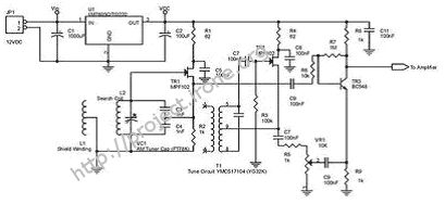
Pulsed Induction Metal Detector
Published:2012/9/13 21:11:00 Author:Ecco | Keyword: Pulsed Induction, Metal Detector
As you can see, there is only one regulated 12 volt supply operating the entire circuit. I was able to do this simply by AC coupling the received signal to U3 via C10. This allowed me to adjust the offset within an operating window. By using a tantalum capacitor of reasonably high capacity, the signal passes with no problems. See Waveforms and Adjustments. This met my first goal.
Source: NEXT.GR (View)
View full Circuit Diagram | Comments | Reading(1564)
Metal Detector using (Beat Frequency)
Published:2012/9/13 21:10:00 Author:Ecco | Keyword: Metal Detector , Beat Frequency
When the signal with a frequency generated by the series of the search coil oscillator oscilator in with the mix-signal blocks of the Beat Frequency Oscilator akan produce a signal with a frequency difference of both frequency and this signal can be heard by human hearing. Voice vote which resulted as beat with a certain rhythm, and often known as the beat note. Changes in frequency depending on the size of the metal detected and the distance between the sensor with a metal detected. Rhythm beat and when this has been strengthened with the amplifier can be connected to a small spekaer beat to listen to the rhythm produced.
Source: NEXT.GR (View)
View full Circuit Diagram | Comments | Reading(1792)
The simplest Metal detector with one BC548
Published:2012/9/13 21:10:00 Author:Ecco | Keyword: simplest, Metal detector, one
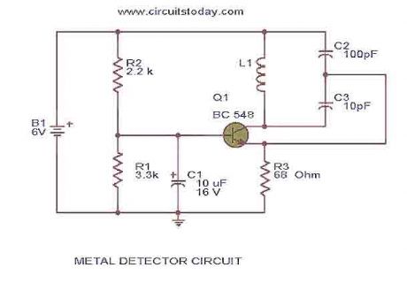
This is the circuit diagram of a low cost metal detector using a single transistor circuit and an old pocket radio..This is nothing but a Colpitts oscillator working in the medium band frequency and a radio tuned to the same frequency.First the radio and the circuit are placed close.Then the radio is tuned so that there is no sound from radio.In this condition the radio and the circuit will be in same frequency and same frequencies beat off to produce no sound.
Source: NEXT.GR (View)
View full Circuit Diagram | Comments | Reading(3886)
One Transistor Metal Detector
Published:2012/9/13 21:09:00 Author:Ecco | Keyword: One Transistor , Metal Detector

This is the design of simple circuit diagram of a low cost metal detector using a single transistor circuit and an old pocket radio. This is nothing but a Colpitts oscillator working in the medium band frequency and a radio tuned to the same frequency. This is the figure of the circuit.
Source: NEXT.GR (View)
View full Circuit Diagram | Comments | Reading(2060)
Zero beat Metal detector
Published:2012/9/13 21:08:00 Author:Ecco | Keyword: Zero beat, Metal detector
This is the design circuit for a sensing the metal. Metal detectors have two oscillators. One is tunable and the other is Fix with a loop. Both are Tuned at same frequency. Outputs from this two oscillators are then mixed in a mixer which produces only the difference. Means, if both oscillators are at the same frequency, there is nothing heard in the speaker. This is the figure of the circuit.
Source: NEXT.GR (View)
View full Circuit Diagram | Comments | Reading(1866)
Beat Balance Metal Detector
Published:2012/9/13 21:07:00 Author:Ecco | Keyword: Beat Balance, Metal Detector
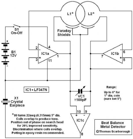
Various embodiments of the BB metal detector have been published, and it has been widely described in the press as a new genre. Instead of using a search and a reference oscillator as with BFO, or Tx and Rx coils as with IB, it uses two transmitters or search oscillators with IB-style coil overlap. The frequencies of the two oscillators are then mixed in similar fashion to BFO, to produce an audible heterodyne. On the surface of it, this design would seem to represent little more than a twinned BFO metal detector.
Source: NEXT.GR (View)
View full Circuit Diagram | Comments | Reading(1399)
Small Metal detector schematic circuit
Published:2012/9/13 21:07:00 Author:Ecco | Keyword: Small Metal detector
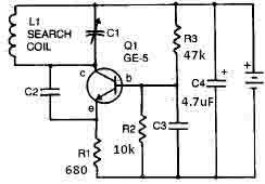
This metal detector circuit needs to be powered using a 9 volts power supply ( DC) or a 9 volts battery . The C1 capacitor is a variable capacitor with a value of 365 pF , C2 is a 100pF silver mica capacitor , C3 is a 0.05 uF disc capacitor and the C4 is a 4.7 uF capacitor . The Q1 transistor can be RCA SK3011 npn transistor or equivalent type and all resistors need to be ? watts.
Source: NEXT.GR (View)
View full Circuit Diagram | Comments | Reading(2804)
BFO metal Detector Circuit
Published:2012/9/13 21:07:00 Author:Ecco | Keyword: BFO, metal Detector
By adjusting the oscillators so their frequencies are very nearly the same, the difference between them is made audible as a beat note, this beat note changes slightly when the search loop is moved over or near to a piece of metal. It has been found in practice best to make the search oscillator fixed say at 100khz and to arrange for the reference oscillator to be adjustable 100khz plus or minus 250hz. This gives a beat note of 250hz to 0 to 250hz. The beat note disappears or nulls when the two oscillators are about equal. This type of detector is most sensitive when the beat note is close to zero, about 5hz ( motor boating ) any slight change being noticeable.
Source: NEXT.GR (View)
View full Circuit Diagram | Comments | Reading(3355)
BFO metal Detector Circuit with IC 4093
Published:2012/9/13 21:06:00 Author:Ecco | Keyword: BFO, metal Detector, IC
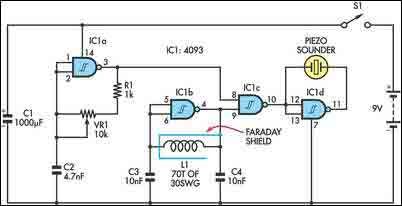
The circuit incorporates two oscillators, both operating at about 40kHz. The first, IC1a, is a standard CMOS oscillator with its frequency adjustable via VR1. The frequency of the second, IC1b, is highly dependent on the inductance of coil L1, so that its frequency shifts in the presence of metal. L1 is 70 turns of 0.315mm enamelled copper wire wound on a 120mm diameter former.
Source: NEXT.GR (View)
View full Circuit Diagram | Comments | Reading(5662)
Bifilar oscillator metal detector
Published:2012/9/13 21:05:00 Author:Ecco | Keyword: Bifilar oscillator, metal detector
Its performance is not comparable to more advanced commercial products, of course, but it still works. Anyway, during WWII metal detectors based on the same principle were utilized my combat engineers of many armies to clear mines. The main idea is really quite simple: build two identical oscillators and adjust them to the same frequency. One of the oscillators uses the search coil while the second one incorporates a variable inductor. When both are operating at the same frequency, the output is zero. If the search coil moves near any metal, however, frequency of the first oscillator shifts and an audible tone is heard in the headphones.
Source: NEXT.GR (View)
View full Circuit Diagram | Comments | Reading(1428)
Mini metal detecror (colpitts oscillator)
Published:2012/9/13 21:04:00 Author:Ecco | Keyword: Mini, metal detecror, colpitts oscillator
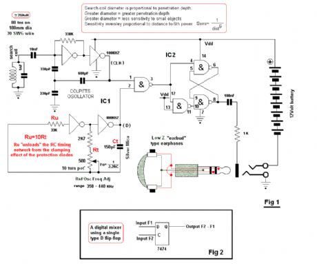
The circuit uses two CMOS IC’s IC1 uses inverters connected as a Colpitts oscillator of 100KHz; the LC frequency determining elements being the search coil and parallel resonating capacitor. An 80 turn close wound 30swg 100mm diameter coil will fit inside the CD case. I will leave the choice of the IC to the reader: this can be any of the well known CMOS inverters or NAND, NOR gates etc configured as an inverters. The choice is yours, use whatever you have on hand. IC2 can be either 74C00 or 4011 quad NAND gates.
Source: NEXT.GR (View)
View full Circuit Diagram | Comments | Reading(2623)
Simple Metal Detector
Published:2012/9/13 21:04:00 Author:Ecco | Keyword: Simple , Metal Detector
The Meter and other small circuit differences, gives better performance. On the Schematic, I show Two Possible Coils. 1) The Ferrite Rod, creates an Accurate Pin Point. But it also has a Very Narrow Detection Field. 2) The Dual Wound Tesla Coil Creates a Wide Field of Detection. With Maximum Sensitivity at the Center of the coil. Detection of metal is with a Meter and LED. The Meter Gives a Much Better Sensitivity.
Source: NEXT.GR (View)
View full Circuit Diagram | Comments | Reading(1248)
Fluid Level Detector (LM1830N)
Published:2012/9/12 21:08:00 Author:Ecco | Keyword: Fluid Level, Detector
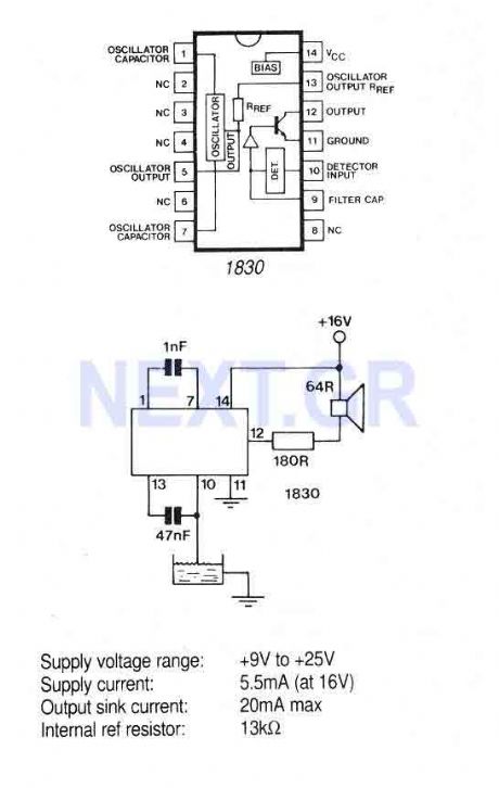
The IC is ideal for detecting the presence, absence or level of water or other conducting liquids. A detector determines the presence or absence of fluid by comparing the resistance of the fluid with the IC's internal reference resistance. An AC signal is used to prevent plating of the probe. When the probe resistance increases the loudspeaker will emit a 500Hz tone.
Source: NEXT.GR (View)
View full Circuit Diagram | Comments | Reading(1252)
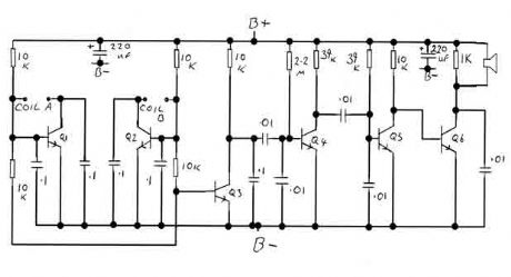
Metal Detector circuit with TDA2822
Published:2012/9/11 21:19:00 Author:Ecco | Keyword: Metal Detector

Here is a simple metal detector with TDA2822 and few NPN transistors. There is a small arrow connected from the Emitter of the T3 to the 10n Capacitor C4. That arrow is simply indicating signal flow as right to left in that particular wire, which is different from the remaining circuit's left to right. (View)
View full Circuit Diagram | Comments | Reading(3771)
Car Exhaust Meter
Published:2012/9/11 20:57:00 Author:Ecco | Keyword: Car Exhaust, Meter
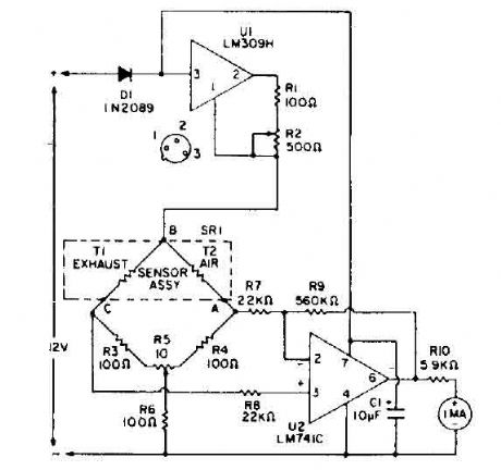
Bridge circuit contains two resistors lOO-ohm (R3 and R4), and two thermistors (Tl and T2). At room temperature, the resistance of T1 and 1'2 is about 2000 ohms. When they are each heated to 150 ° C by an RNA 10 current, the resistance value decreases to 100 ohms. So. the four elements include a bridge circuit. CO is a characteristic that conducts heat from a thermistor at a rate different from that of air. A thermistor, TI, is exposed to automobile exhaust, while the other, 1'2, is isolated in an environment of clean air. Unlike thermal conduction bridge imbalance. A voltage difference is caused between points A and C. A differential amplifier. VI, amplifies this difference and leads to the counter with a current sufficient to read the percentage of CO and air-fuel ratio. A control panel before the balance, R5, balances the bridge and calibrates the instrument. The calibration is performed when both thermistors are exposed to outside air. (View)
View full Circuit Diagram | Comments | Reading(2045)
| Pages:21/101 At 202122232425262728293031323334353637383940Under 20 |
Circuit Categories
power supply circuit
Amplifier Circuit
Basic Circuit
LED and Light Circuit
Sensor Circuit
Signal Processing
Electrical Equipment Circuit
Control Circuit
Remote Control Circuit
A/D-D/A Converter Circuit
Audio Circuit
Measuring and Test Circuit
Communication Circuit
Computer-Related Circuit
555 Circuit
Automotive Circuit
Repairing Circuit