
Measuring and Test Circuit
Index 35
FIELD_STRENGTH_METER
Published:2009/7/13 5:16:00 Author:May
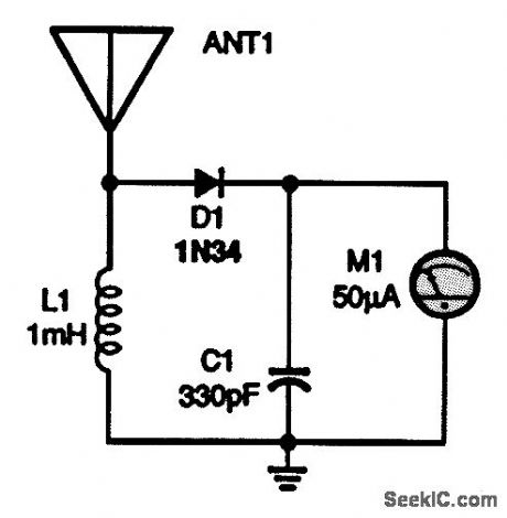
This simple field-strength meter is great for tuning transmitters or antennas. It's a tool no ham should be without. The antenna is a 24-in whip. (View)
View full Circuit Diagram | Comments | Reading(0)
VISUAL_AND_AUDIBLE_HEADLIGHT_MONITOR
Published:2009/7/13 5:16:00 Author:May
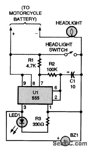
If the LED in this circuit is flashing and the piezo sounder is buzzing, then your headlights are not on. (View)
View full Circuit Diagram | Comments | Reading(1069)
SIMPLE_CONTINUITY_TESTER
Published:2009/7/16 2:38:00 Author:Jessie
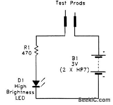
This figure shows the circuit for a simple, but safe, continuity tester. (View)
View full Circuit Diagram | Comments | Reading(0)
CONTINUITY_CHECKER
Published:2009/7/16 2:35:00 Author:Jessie
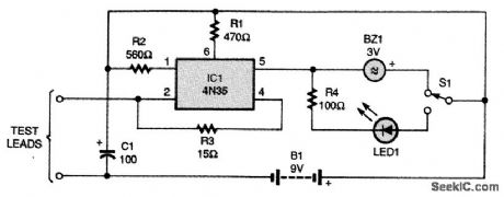
The checker is built around a 4N35 optocoupler. When the test leads are shorted by a resistance, it turns IC1 on by pulling pins 2 and 4 low, allowing current to flow through pins 6 and 5. The current to pin 5 flows through either the buzzer or the LED, depending on the position of S1. To test continuity of 50Ω or less, use the buzzer as the indicator. For continuity of up to 1000Ω, use the LED. The circuit can also be used to check PN junctions of transistors and diodes, with less possibility of damaging such sensitive components. For that, use the LED, and connect the lead from pin 2 of IC1 to the P side. The supply can be from 7.5 to 9V. To catch fast pulses, trigger a monostable with pin 5, and use it to drive the LED and the buzzer. The monostable will act like a pulse stretcher. (View)
View full Circuit Diagram | Comments | Reading(0)
28_VAC_CURRENT_LIMITER
Published:2009/7/13 5:00:00 Author:May
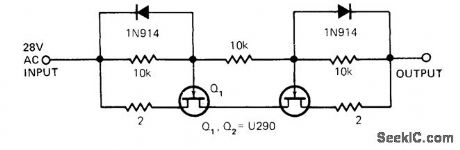
Dual JFETs in voltage-sharing arrangement protect output of 28-VAC power amplifier. Transistors should be matched for IDSS. During positive half-cycle of input, Q2 operates as current Iimiter and Q1 as source follower. If Q1 does not supply enough current, drain voltage of Q2 drops and makes Q1 turn on further. Conversely, if Q1 supplies too much current, Q2 drain voltage rises and tends to turn Q1 off. On negative half-cycle, Q1 becomes limiter and Q2 is source follower. -J. P. Thompson, Current Limiter Protects Amplifier from Load Faults, EDN Magazine, June 5, 1978, p 148 and 150. (View)
View full Circuit Diagram | Comments | Reading(806)
DIGITAL_FIELD_STRENGTH_METER
Published:2009/7/13 4:54:00 Author:May
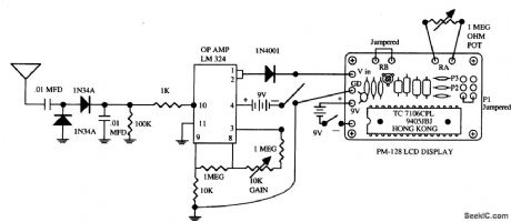
This field-strength meter uses a surplus LCD panel meter display, but any suitable unit (1 V full scale, etc.) can be used. RF is detected by a pair of 1N34 diodes and fed to an LM324 op amp acting as a dc amplifier whose gain is set via a 1-MΩ pot. The op-amp output drives the LCD panel meter. (View)
View full Circuit Diagram | Comments | Reading(3175)
COUNTING_RATE_METER
Published:2009/7/13 4:49:00 Author:May

Uses three Optical Electronics 9827 opamps to amplify, square up, and integrate input pulses from event detector, to give integrated DC voltage that is function of counting rate. This voltage is compressed by 2538 DC logamp having 60-dB dynamic range for driving chart recorder. Values of R and C de-pend on counting rate, Well-regulated power supply is required because this determines am-plitude of squared pulses that drive integrator. Applications include counting photons of photomultiplier or nuclear particles of solid-state detector. Logamp compresses output of integrator to eliminate need for scale changing while giving constant accuracy over wide dy-namic range of counting rates. - Logarithmic Counting Rate Readout, Optical Electronics, Tucson, AZ, Application Tip 10106.
(View)
View full Circuit Diagram | Comments | Reading(934)
CAR_PRESENCE_DETECTOR
Published:2009/7/13 4:48:00 Author:May
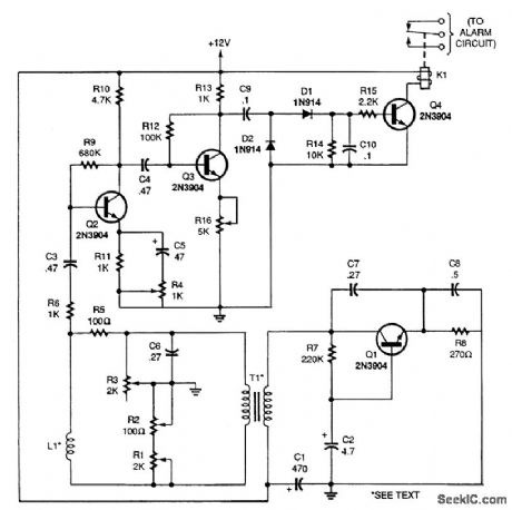
Here's a circuit that will, if calibrated carefully, detect the presence of a large metal object. Coil L1 is made by winding 50 turns of 26-gauge wire on a 50-inch form. If L1 is buried in the ground, the circuit can be used to detect any car or truck that is driven over the coil. Transistor Q1 and its surrounding components make up a Coipitts oscillator, operating at 10 kHz. The output is coupled to a Maxwell bridge through the secondary of T1, which is a 600-Ω-to-600-Ω audio coupling transformer. With R1, R2, and R3 set properly, the bridge is balanced when no metal is close to L1, producing a near-zero ac signal at the bridge's output (the R5/L1 junction and ground). Should a large enough ferromagnetic object pass over L1, the bridge becomes unbalanced, producing a signal at the junction of R5 and L1. That signal is fed to the base of Q2, part of a common-emitter amplifier stage. Resistor R4 adjusts to the gain of that stage. The signal from the amplifier is fed to the base of Q3, which drives a voltage doubler that supplies current to the relay driver, Q4. The relay, K1, is a 1000-Ω, sensitive, 12-V unit that can drive a normally open or closed alarm circuit to indicate the presence of a vehicle. Use shielded cable to attach L1 to the circuit, and do not bury L1 deeper than 8 inches for best results. Remember to weatherproof all components that will reside outside. (View)
View full Circuit Diagram | Comments | Reading(1274)
MULTIMETER_CONDUCTANCE_ADAPTER
Published:2009/7/16 3:44:00 Author:Jessie
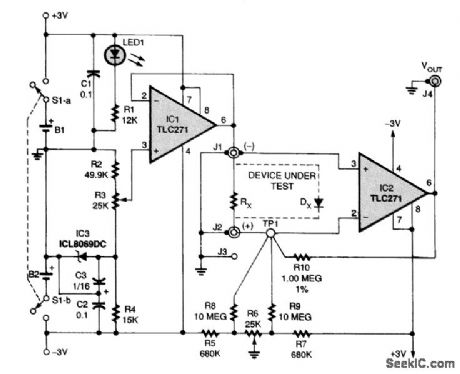
A 1.000-V reference is buffered by IC1, a TLC271, and is connected to J1 for use when measuring conductance. The voltage reference is derived from IC3, a 1.25-V temperature-compensat ed band-gap reference. The current drop developed by the component under test at J1 and J2 is converted by IC2 to an output voltage that can be displayed on a digital voltmeter. The output voltage is limited to a maximum of 2.0V and a minimum of 1.0 V. With the inverting input of IC2 at virtual ground, the maximum input current that can be measured is -2.0 μA. In reading the conductance of an unknown resistor (labeled RX, in the figure), -1.0 V is applied to J1, with J2 being at virtual ground. Based on the maximum input current that can be converted by IC2, the smallest resistance that can be measured is 500,000Ω. The values chosen for the circuit generate a conductance reading of 1.0 μmho/V, or 1.0 nmho/mV output. A 1.0-MΩ resistor will have a conductance of 1.0 pmho, or 1000 nmho. A 1.0-GΩ resistor would have a conductance of 1.0 nmho. The current-to-voltage conversion is set by R10, which gives an output of 1 V/μA, or 1 mV/nA. The lowest tolerance you should use for R10 is 1 percent. (View)
View full Circuit Diagram | Comments | Reading(3099)
SIMPLE_INDUCTANCE_METER
Published:2009/7/16 3:38:00 Author:Jessie
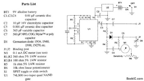
This figure shows the schematic diagram of the simple inductance meter. U1, a 74LS00 two-input quad NAND gate logic integrated circuit, two resistors, a capacitor, and a surplus microprocessor crystal form a stable crystal oscillator near the marked frequency of the crystal. The RF voltage is taken from pin 8 through isolation capacitor C3 to the measuring circuit. RF voltage is applied through capacitor C7 to J1, a bindiftg post. This same RF voltage is applied to a resistive voltage divider consisting of R3 and R4. Germanium diode D1 has its anode connected to the junction between R3 and R4. RF across the variable tuning capacitor C6 is applied back through C5 to the cathode of D1 and load resistor R5, the lower end of which is bypassed to ground through C4 and applied to the positive terminal of meter M1. R6 is a sensitivity control connected between the negative terminal of meter M1 and ground. This instrument operates by measuring the RF voltage developed across C6, which will be the highest when the series circuit made up of C6 and the unknown inductance is at resonance at the crystal frequency. In other words, the value of the unknown is indicated on the dial attached to C6 when the voltage indicated by M1 peaks, just the opposite of bridge operation. (View)
View full Circuit Diagram | Comments | Reading(6626)
SIMPLE_SWR_BRIDGE
Published:2009/7/16 3:35:00 Author:Jessie

This circuit can be used to measure SWR. It uses a coupler made from a 6.5-inch piece of RG-58A/U coax. First remove the outer plastic jacket, then open up the braid a little bit. Next, thread two lengths of #22 tinned bus wire into Teflon spaghetti. Then thread the insulated wires inside the braid, trying to keep them on opposite sides of the center conductor. Be careful to keep the leads to the 1N67A diodes and the 150-Ω resistors very short. If you can't find 1N67A diodes, use 1N34. The RG-58A/U braid should, of course, be grounded at both ends. If the device is carefully constructed, the result should be a perfectly balanced VSWR meter. It should need no adjustment. (View)
View full Circuit Diagram | Comments | Reading(5691)
CHRONOMETER_COUNTER
Published:2009/7/16 3:33:00 Author:Jessie
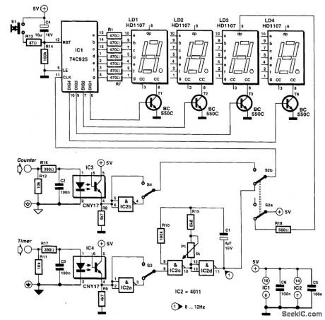
The chronometer has four 7-segment displays, which can show a time lapse of 000.0 s to 999.9 s with a resolution of 0.1 s or a count from 0000 up to 9999. The chronometer is based on the type 74C925 counter IC with integrated display driver from National Semiconductor. The device draws a current of about 40 mA from a +5-V supply. On power-up, the counter is set to 0000 by network R14-C4 or by S1. The IC can derive a clock from two different sources: the internal oscillator or an external one via the COUNT input. The oscillator is formed by IC2c and IC2d and is enabled via the timer input. The enabling is effected manually by S3 or by inputting a given level, high or low, depending on the position of 53, into CHRON. The timer and counter inputs are identical, but are separated electrically from one another and from the signal source by optoisolators. This allows input potentials of up to 25 VP-P to be applied to either of them. As with the timer input, the level at the COUNT input can be either high or low and is selected by S4. The position of S2b determines whether the time or count function is active. Switch section S2a inserts the decimal point between the third and fourth display digits when the timer is selected. Whereas a simple level is needed to start the oscillator, the signal at the COUNT input needs more if the module is to work error-free. The signal must have steep edges; it must be free of interference; at low level, it must be well below 1V; and at high level, it must well above 2V. Moreover, if a switch is used at the COUNT input, it must be debounced adequately. (View)
View full Circuit Diagram | Comments | Reading(5571)
COMPONENT_CHECKER
Published:2009/7/16 3:27:00 Author:Jessie
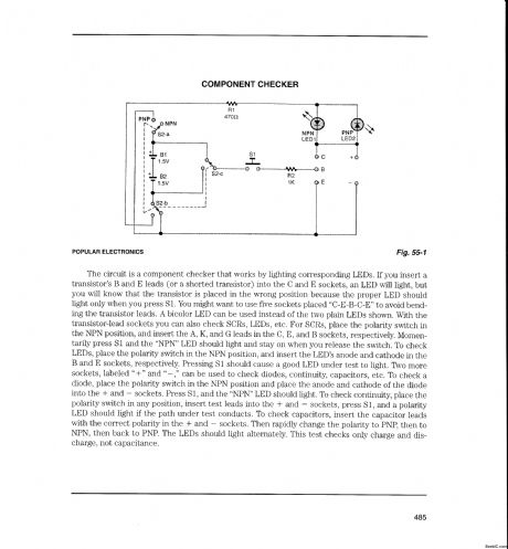
The circuit is a component checker that works by lighting corresponding LEDs. If you insert a transistor's B and E leads (or a shorted transistor) into the C and E sockets, an LED will light, but you will know that the transistor is placed in the wrong position because the proper LED should light only when you press S1. You might want to use five sockets placed C-E-B-C-E to avoid bend-ing the transistor leads. A bicolor LED can be used instead of the two plain LEDs shown. With the transistor-lead sockets you can also check SCRs, LEDs, etc. For SCRs, place the polarity switch in the NPN position, and insert the A, K, and G leads in the C, E, and B sockets, respectively. Momentarily press S1 and the NPN LED should light and stay on when you release the switch. To check LEDs, place the polarity switch in the NPN position, and insert the LED's anode and cathode in the B and E sockets, respectively. Pressing S1 should cause a good LED under test to light. Two more sockets, labeled + and -, can be used to check diodes, continuity, capacitors, etc. To check a diode, place the polarity switch in the NPN position and place the anode and cathode of the diode into the + and - sockets. Press S1, and the NPN LED should light. To check continuity, place the polarity switch in any position, insert test leads into the + and - sockets, press S1, and a polarity LED should light if the path under test conducts. To check capacitors, insert the capacitor leads with the correct polarity in the + and - sockets. Then rapidly change the polarity to PNP, then to NPN, then back to PNP. The LEDs should light alternately. This test checks only charge and discharge, not capacitance. (View)
View full Circuit Diagram | Comments | Reading(1150)
BATTERY_ORANKING_TESTER
Published:2009/7/13 4:43:00 Author:May
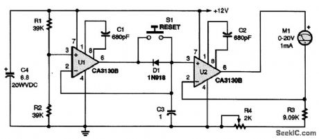
Need to discover if your battery is weak or if your starter's windings are shorted? This meter will display how low your battery voltage drops during a start. The circuit is a negative-peak reading voltmeter. (View)
View full Circuit Diagram | Comments | Reading(1038)
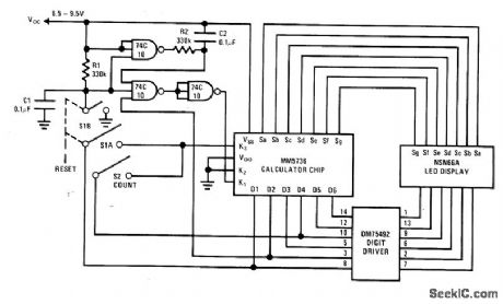
CALCULATOR_COUNTS_UP_TO_300_Hz
Published:2009/7/13 4:33:00 Author:May
Logic elements used with MM5736 calculator chip provide self-starting counting action In range from 80 to 300 Hz,Increase In counting rate is obtained by feeding digit output 6 back to digit output 4, to bypass some internal logic of calculator. -M. Watts, Calculator Chip Makes a Counter, National Semiconductor, Santa Clara, CA, 1974, AN-112、p4 (View)
View full Circuit Diagram | Comments | Reading(2159)
TWO_CHIP_COUNTER
Published:2009/7/13 4:31:00 Author:May
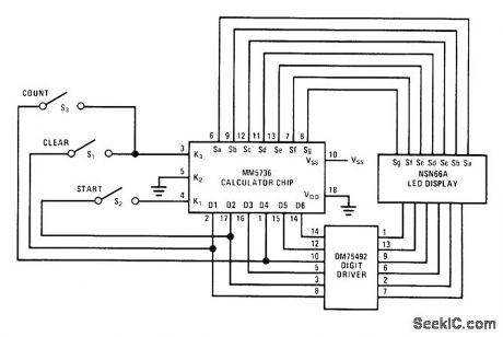
Combination of Na-tional MM5736 calculator chip and DM75492 digit driver for 6-digit LED display is suitable for applications where typical maximum counting rate can be about 100 Hz. Counter is reset manually by closing S1 to clear calculator and closing S2 to enter a 1. Operator now controls start of new count by pressing S,, without need for gating count input. -M. Watts, Calculator Chip Makes a Counter, National Semiconductor, Santa Clara, CA, 1974, AN-112, p 2. (View)
View full Circuit Diagram | Comments | Reading(1067)
SELF_DRIVING_COUNTER
Published:2009/7/13 4:29:00 Author:May

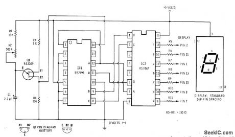
UJT relaxation oscillator Q1 supplies series of pulses to input pin 14 of RS7490 decade counter at frequency determined by setting of R2 and value used for C1 Counter feeds corresponding BCD outputs to BCD input pins of RS7447 decoder for conver-sion into 7-segment decimal format for driving Radio Shack 276-052 LED display. Ideal for class-room demonstrations a nd Science Fair exhibits. 6-V battery with 1N914 diode in series can be used in place of 5-V supply. -F. M. Mims, In-tegrated Circuit Projects, Vol. 2, Radio Shack, Fort Worth, TX, 1977, 2nd Ed., p 41-56. (View)
View full Circuit Diagram | Comments | Reading(3748)
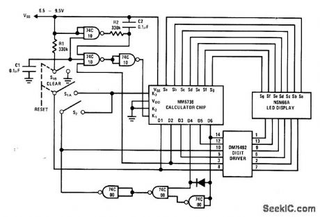
CALCULATOR_COUNTER
Published:2009/7/13 4:27:00 Author:May
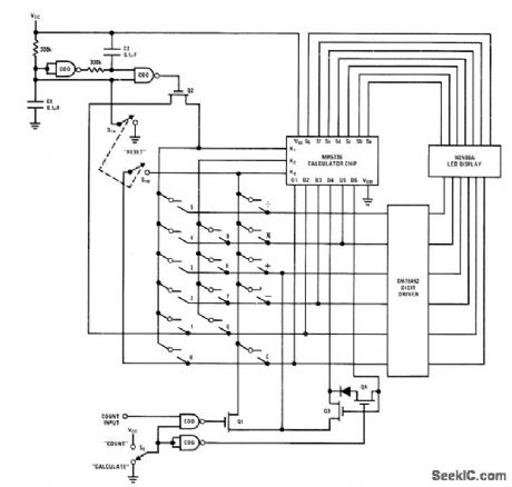
Normal arithmetic functions of National MM5736 calculator chip are preserved while providing counting capa-bility, through use of M0S transistors Q1-Q4.When reset switch is pushed, pin D1 is connected to pin K3 of calculator and calculator is cleared. C1 and C2 are discharged while S1 is closed but are charged when it is released, generating negative-going delayed pulse that causes a 1 to be entered into calculator. Delay allows clear function to Ue debounced by calculator chip. When S2 is in count mode, Q4 is turned on and D6 is tied to D4, for doubling maximum counting rate. Input pulse will now tum Q1 on, making calculator perform addition. Additional pulse adds 1 to sum. When S2 is rei turned to calculate position, keyboard Iogic is returned to normal state. MM74C00 NAND gates can be replaced with MM74C02 N0R gates, and M0S transistors can be replaced with MM5616 CMOS switch. -M. Watts, Calculator Chip Makes a Counter, National Semi-conductor, Santa Clara, CA, 1974, AN412, p 6. (View)
View full Circuit Diagram | Comments | Reading(1405)
TIME_BASE_FOR_12_GHz_COUNTER
Published:2009/7/13 4:23:00 Author:May

Provides 1-s gate, latch strobing signals, 1-kHz signal for multiplexing displays, and digital sample rate control for high-frequency high-resolution counters. Timing chain divides 1.MHz external reference signal by 106 to give 1.Hz output. MC14534 five-decade counter generates 1-kHz multiplexing frequency with 20% duty cycle for blanking. Digital sample rate control is pro-grammed on BCD thumbwheel switch in incre-ments ranging from 1 to 9 s, using single MC14522 BCD down counter. -J. Roy, A Time Base and Control Logic Subsystem for High-Fre-quency, High-Resolution Counters, Motorola, Phoenix, AZ, 1975, EB-48. (View)
View full Circuit Diagram | Comments | Reading(1648)
CALCULATOR_AS_COUNTER
Published:2009/7/13 4:21:00 Author:May
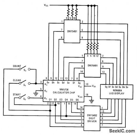
National MM5736 calculator chip is used with two DM75491 segment drivers and DM75492 digit driver for LED 6-digit display. Switches provide manual control of counter. To reset, push S1 to clear calculator, push S2 to enter a 1, then push S3 when new count is to be started. Current drive to LEDs is supplied by Vcc through cur rent-limiting resistors, giving power saving be-cause Vcc can be less than Vss. Will drive large LED display. -M. Watts, Calculator Chip Makes a Counter, National Semiconductor, Santa Clara, CA, 1974, AN-112, p 4. (View)
View full Circuit Diagram | Comments | Reading(1184)
| Pages:35/101 At 202122232425262728293031323334353637383940Under 20 |
Circuit Categories
power supply circuit
Amplifier Circuit
Basic Circuit
LED and Light Circuit
Sensor Circuit
Signal Processing
Electrical Equipment Circuit
Control Circuit
Remote Control Circuit
A/D-D/A Converter Circuit
Audio Circuit
Measuring and Test Circuit
Communication Circuit
Computer-Related Circuit
555 Circuit
Automotive Circuit
Repairing Circuit