
Measuring and Test Circuit
Index 15
Product Detector
Published:2012/12/6 19:39:00 Author:muriel | Keyword: Product Detector
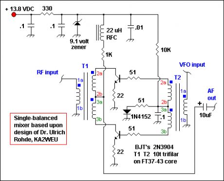
A product detector using either one or more 2N3904 transistors was originally planned and indeed, four designs were built and tested. The 2 favorite detectors were a single-ended detector built with a single BJT which maybe used in an future novelty transceiver project and a passive mixer invented by Dr. Ulrich Rohde. The original mixer called for 2N5179 transistors and used a 0.1 uF coupling cap to the diplexer stage for RF output. It should have a VCC of 9 volts DC.
The mixer as built for this project is shown to the right.
The mixer as designed by Rohde had a reported IP3 of 33 dBm with a LO drive of 15-17 dBm and an insertion loss of ~ 6dB. This mixer operates in push-pull and the 22 ohm resistors on the transistor emitters provide degenerative feedback which makes component matching unnecessary. The schematic and brief write up can be found in QST for June 1994 in an article entitled Key Components of Modern Receiver Design-Part 2. See references 1 and 2.
I built 2 versions of Rohde's mixer and tested them both in the receiver shown in the main schematic. I later discarded this design and replaced it with the familiar diode ring mixer for the following subjective reasons; I noted a greater insertion loss, more hum and noise, higher LO drive level requirements and more WWV AM interference when compared to a diode ring mixer.
No quantitative measurements of the mixer were made. Listening tests and observations were only performed. Careful shielding of one version of the mixer resulted in a major improvement in hum and obliteration of an audio feedback problem noted when the AF gain was increased maximally when compared to the unshielded second version of the mixer. In addition, better performance would most certainly be realized if 2N5179 BJT's had been used instead of 2N3904's. Rohde's mixer certainly warrants further and better analysis with quantitative testing for use in home built receivers.
If you build and test this mixer, please forward or publish the results for use by the Amateur Radio community. The trifilar wound transformers are identical to those shown elsewhere on this site and have phasing dots and coil numbering included for reference. Ugly constructing this mixer is extremely easy to do. The diode ring mixer ultimately used has 50 ohm ports and can be a homebrew or commercial unit such as the popular SBL-1 from Mini-Circuits. (View)
View full Circuit Diagram | Comments | Reading(0)
Diode Matching for Mixers
Published:2012/12/6 1:31:00 Author:muriel | Keyword: Diode Matching, Mixers
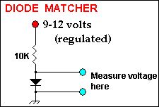
For optimal results Schottky or Hot-Carrier diodes should be used. However, common diodes such as the 1N914, 1N4148 or 1N4454 are all quite suitable and are much cheaper. The four ring diodes should be matched to help mixer balance and thus carrier suppression. At MF and HF the most critical matching required is the forward voltage drop across the diode and this is easily performed with a sensitive voltmeter.
Set your voltmeter on the 2 volt scale to give you 3 decimal places for matching the voltage drops. Try and find 4 diodes close to one another. In addition, best results maybe obtained if all the diodes are the same type (i.e. all 1N4148) and if they are all from the same manufacturer. Look above for easy schematic to match your diodes with a voltmeter. Give the diode under test at least 20 seconds to warm up and stabilize before taking your voltage measurement.
(View)
View full Circuit Diagram | Comments | Reading(2379)
Product Detector and Diplexers
Published:2012/12/6 1:28:00 Author:muriel | Keyword: Product Detector, Diplexers

The 50 ohm diode ring product detector can be commercial units such as the Mini-Circuits SBL1 or TUF-1 or homebrewed 50 ohm impedance units. Five simple diplexers are shown in the lower Adjuncts schematic for you to choose from. The one you choose will depend on available parts, cost and your requirements in a popcorn receiver such as this. These diplexers are mostly of the low pass filter variety and provide a ~50 ohm termination to the diode ring mixer and some matching to preserve the product detector dynamic range. I realize that except for (A) and (D) these audio frequency filters are not truly diplexers and will not provide DC to daylight matching. The intent of this web site is not high performance-high cost design and please do not confuse it as such. Note that electrolytic capacitors that bypass to ground such as the 1 uF caps must be non-polarized or bipolar for best results.
The (A) diplexer is by W7ZOI and is described on the Diplexer Web Page on this site.
The (B) and (D) diplexers are my designs and the (D) diplexer is the (B) diplexer with out the high pass component.
The (B) diplexer shown has a 3000 hertz 2 pole high pass/2 pole low pass design. This 2nd order filter provides reasonable overall matching Capacitors are standard-value, non-polar electrolytic types.
The (C) diplexer is a very basic, but very practical choice for this receiver.
The (E) diplexer is one that I used in one of my first DC receivers and the 47 millihenry inductor is a standard value unit sold by Mouser Electronics and others.
Another diplexer choice for this receiver might be the unit described by Rick Campbell, KK7B in his Binaural I-Q receiver project published in the March 1999 issue of QST. (View)
View full Circuit Diagram | Comments | Reading(2575)
Unijunction transistor working performance speed measurement circuit
Published:2012/12/5 21:30:00 Author:Ecco | Keyword: Unijunction transistor, working performance , speed measurement
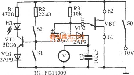
Measured single-junction transistor VBT ( set: BT33) and R3, C2 form relaxation oscillator. When VBT gets conduction, transistor VT1 obtains bias current by the bias resistor R2 ( S1 is OFF, S2 is closed), the light - emitting diode H1 emits light. +10 V power supply charges for C2 by R3 and VD2. The voltmeter V measured voltage across C2 will rise over time, when the E terminal potential reaches peak voltage of VBT, the VBT's E to B1 will be automatically turned on.
(View)
View full Circuit Diagram | Comments | Reading(1363)
Sound Level Meter
Published:2012/12/4 23:56:00 Author:muriel | Keyword: Sound Level Meter
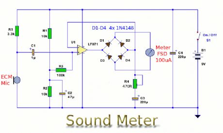
This is a simple, battery operated, sound level meter using a microphone as input for comparison of sound levels. (View)
View full Circuit Diagram | Comments | Reading(0)
Simple Wideband RF Millivoltmeter
Published:2012/12/4 23:55:00 Author:muriel | Keyword: Simple Wideband , RF Millivoltmeter
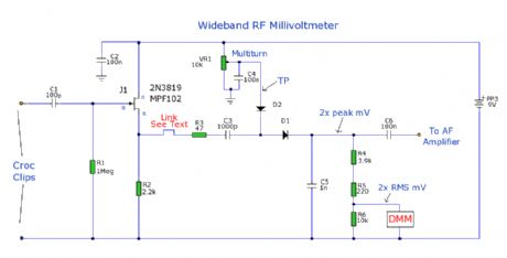
Professional test equipment is expensive to buy or hire. But the opportunity is here as below, to emulate a commercial RF millivoltmeter in cheap and simple terms, by its DC output driving a digital multimeter display.
In lieu of access to a radio communications test set, frequency bandwidth response can only be estimated as being good to a few hundred Mhz and an input level range from 1mV to a couple of volts rms. Perhaps a reader giving feedback to CXI could firm up these estimates with proper lab kit.
So the finished unit will do a satisfactory job for hobby use in fault tracing, gain measurement and general radio test work. Don't forget to halve the indicated DMM reading for the true rms input!
Please note this unit is NOT intended to measure RF power, as its sensitive components would be destroyed by the inputting of high RF voltages. (View)
View full Circuit Diagram | Comments | Reading(4498)
50hz Calibration aid for Multimeters
Published:2012/12/4 23:54:00 Author:muriel | Keyword: 50hz , Calibration aid, Multimeters
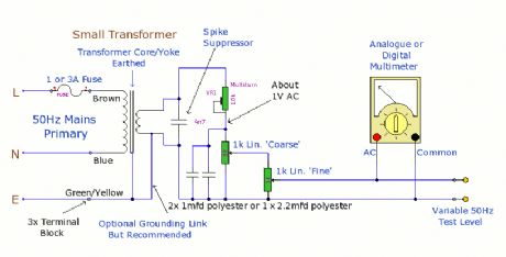
The purpose of this prototype unit does away with the need for an oscillator. It offers a mains-derived and fully variable 50 hz AC volts down to millivolts for comparison and to check accuracy, of two or more parallel connected multimeters. (View)
View full Circuit Diagram | Comments | Reading(1176)
PC Scope Probe
Published:2012/12/4 23:53:00 Author:muriel | Keyword: PC Scope Probe
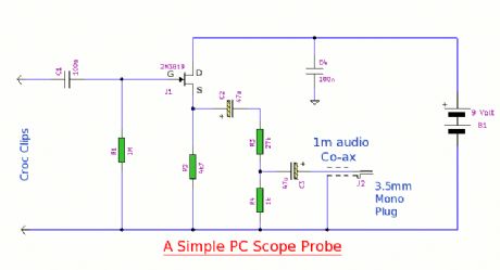
This simple pc scope probe is nothing more than a fet follower. It has a high input impedance and a low output impedance to match a mic or line input socket on a pc or laptop. (View)
View full Circuit Diagram | Comments | Reading(1419)
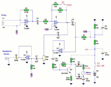
Small General Purpose Audio Test Set
Published:2012/12/4 23:52:00 Author:muriel | Keyword: Small General Purpose, Audio Test Set
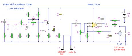
This is a small general purpose audio test set. It comprises a low 0.3% distortion phase shift oscillator and a level meter. The level meter is set at 100mV FSD and can be used for gain measurements and general testing. Current consumption is just under 4mA. (View)
View full Circuit Diagram | Comments | Reading(1633)
RF Probe
Published:2012/12/4 23:52:00 Author:muriel | Keyword: RF Probe
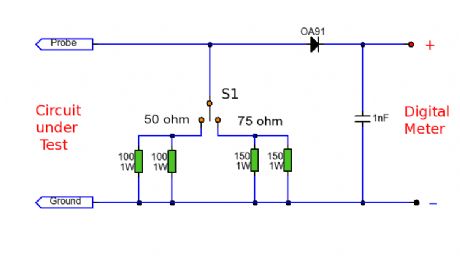
This RF probe can be used at High Frequency (HF) or Ultra High Frequency (UHF) on both 50 and 75 ohm coaxial cables. In addition the RF voltage can be measured under load or no-load conditions which allows the circuit to double as an RF Watt meter. The RF probe can be used for oscillators and small transistors for powers up to 2 Watts. (View)
View full Circuit Diagram | Comments | Reading(0)
Transistor Tester
Published:2012/12/4 23:51:00 Author:muriel | Keyword: Transistor Tester
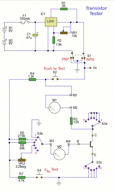
A test circuit for BJT (Bipolar Junction Transistors). This circuit can measure both small signal hfe and DC current gain hFE of a low to medium power power transistor. In addition it can measure collector-base and collector-emitter leakage current. This circuit can also measure hFE at different operating points. A multimeter can be used at multiple test sockets to make all measurements, or two DC ammeters can be used. (View)
View full Circuit Diagram | Comments | Reading(0)
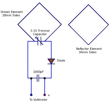
Field Strength Meter for 2.4 Ghz Wireless LAN
Published:2012/12/4 23:50:00 Author:muriel | Keyword: Field Strength Meter, 2.4 Ghz, Wireless LAN
View full Circuit Diagram | Comments | Reading(3155)
EMF Probe Version 2
Published:2012/12/4 23:49:00 Author:muriel | Keyword: EMF Probe
View full Circuit Diagram | Comments | Reading(1879)
Coil Coupled Operation Metal Detector
Published:2012/12/4 23:48:00 Author:muriel | Keyword: Coil Coupled Operation, Metal Detector
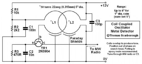
A Coil Coupled Operation Metal Detector made from readily obtainable components and using an ordinary medium receiver as a detector. (View)
View full Circuit Diagram | Comments | Reading(3553)
Temperature measuring circuit
Published:2012/12/3 21:38:00 Author:Ecco | Keyword: Temperature measuring
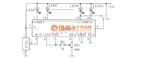
In the figure, S1 is the point / bar display mode changeover switch. When the power supply voltage Vcc> 8V, LED1 ~ LED10 don't need to use limiting resistor connected in series. When LED is lit, the cuttent is set by external resistor connected to pin 4,6, assuming pin 4,6 external resistor is 1.2kΩ ( inlcuding the resistance between the resistor R1, BP1 center head and pin 4), 10kΩ resistor is connected in parallel with the LM3914 internal divider, the equivalent resistance between pin 4 and pin 6 is about 10.7kΩ, the current of voltage divider circuit provided by 1.25V reference voltage is 1.25V/1.07kΩ ≈ 1.2mA.
(View)
View full Circuit Diagram | Comments | Reading(1174)
The speed tester circuit for testing transistor quality
Published:2012/12/3 20:33:00 Author:Ecco | Keyword: speed tester, testing , transistor quality
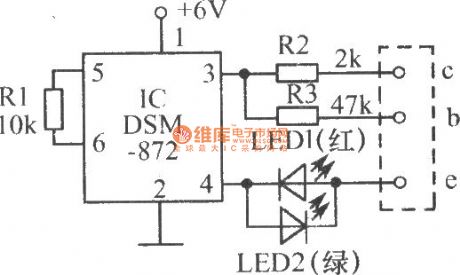
(1) The inserted NPN transistor is intact. IC's pin 3 is high, pin 4 is low, then the tested tube gets conduction, red light-emitting diode LED1 is light; when IC's pin 3 is low, pin 4 is high, then the tube is cut-off, LED1 and LED2 do not shine, the general view is twinkling light from LED1.
(View)
View full Circuit Diagram | Comments | Reading(1428)
Human reaction speed tester
Published:2012/12/3 21:13:00 Author:Ecco | Keyword: Human reaction , speed tester
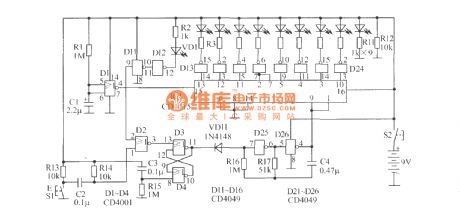
NAND gate D25, D26 form multivibrator which outputs the clock pulse with approximately 50ms cycle. IC1 can form an 8 - bit right shift register, and D1 forms a starting up delay circuit output, of which signal is used as its serial input data. When the machine starts, since D1 output is 1 , under the effect of clock pulses, IC1's all 8-bit Storage units quickly become 1 , after 3s ~~ 4s, D1 output becomes 0 , then tested light VD1 is lit.
(View)
View full Circuit Diagram | Comments | Reading(1765)
Beat Balance Metal Detector circuit
Published:2012/12/3 20:44:00 Author:muriel | Keyword: Beat Balance, Metal Detector circuit

View full Circuit Diagram | Comments | Reading(1928)
Two Simple Crystal Test Circuits
Published:2012/12/3 20:41:00 Author:muriel | Keyword: Two Simple Crystal, Test Circuits
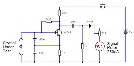
Two simple test circuits to check operation of quartz crystals. (View)
View full Circuit Diagram | Comments | Reading(1476)
Connection Tester
Published:2012/12/3 20:40:00 Author:muriel | Keyword: Connection Tester

A low resistance ( 0.25 - 4 ohm) continuity tester for checking soldered joints and connections. (View)
View full Circuit Diagram | Comments | Reading(1237)
| Pages:15/101 1234567891011121314151617181920Under 20 |
Circuit Categories
power supply circuit
Amplifier Circuit
Basic Circuit
LED and Light Circuit
Sensor Circuit
Signal Processing
Electrical Equipment Circuit
Control Circuit
Remote Control Circuit
A/D-D/A Converter Circuit
Audio Circuit
Measuring and Test Circuit
Communication Circuit
Computer-Related Circuit
555 Circuit
Automotive Circuit
Repairing Circuit