
Measuring and Test Circuit
Index 7
SENSITIVE GEOMAGNETIC DETECTOR
Published:2013/5/7 21:14:00 Author:muriel | Keyword: SENSITIVE GEOMAGNETIC DETECTOR
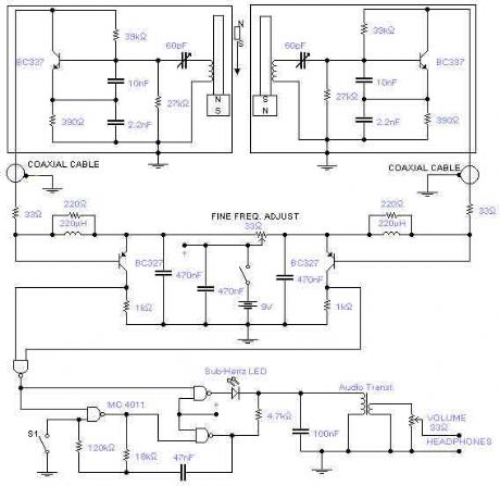
This is a rather sensitive circuit which will detect minute variations of a magnetic field, particularly the Earth magnetic field. The principle is based on an audio beat tone generated by two identical oscillators. These must be built in the same manner with the same type of components. In this way we minimize influence from temperature and voltage variations. The two oscillators, called probes, are housed in plastic boxes padded, on the inside, with copper wires terminated in one point only and running parallel to the ferrite rod. This rod, together with the coil was removed from an old Medium Wave radio and a small and powerful magnet was glued on one side. An extra magnet was placed on the outside of one of the boxes in order to set the initial or zero beat tone. This magnet is rotated or moved up and down until you hear the right frequency. A small hole is made in each plastic box in order to adjust the trimmer capacitor. Switch S1 will enable the sub-Hertz detector: in this way you will be able to hear the beat note even if the difference between the two probes is below the threshold level of around 20Hz and you will pick up differences well below 1Hz. The two probes are connected to the main box using standard RG58 coaxial cable tested up to a length of 15m. Operating frequency is 1.25MHz and it is sensitive enough to feel the rotation of a speaker magnet 2m away. Battery voltage is 9V. (View)
View full Circuit Diagram | Comments | Reading(2172)
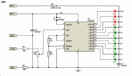
LED Audio VU Meter
Published:2013/4/26 1:37:00 Author:muriel | Keyword: LED , Audio , VU Meter
View full Circuit Diagram | Comments | Reading(2350)
Stereo VU Meter
Published:2013/4/26 1:36:00 Author:muriel | Keyword: Stereo VU Meter
This is a STEREO LED LEVEL METER. It’s the cheapest and best bar graph display available and best of all, it uses readily available components.You only need a handful of LEDs, 22 transistors, some resistors, diodes and a set of electros – it doesn’t require any chips. (View)
View full Circuit Diagram | Comments | Reading(2240)
Voltage and Current Limited Audible Continuity Tester circuit
Published:2013/3/29 4:31:00 Author:Ecco | Keyword: Voltage and Current, Limited Audible, Continuity Tester
Using this continuity tester circuit, a failure of PCB tracks be examined without looking directly at the tracks routing, which is can be very frustrating. The indication of this circuit is done by an audible alarm (a buzzer). This circuit can be used to indicate continuity below any resistance value up to 35 ohms by adjusting the circuit. To make sure this circuit doesn’t damage any installed parts on the board, the voltage and current of this circuit is limited. Here is the schematic diagram of the circuit:
(View)
View full Circuit Diagram | Comments | Reading(1587)
True Stereo Indicator Detecting L-R Signal Difference circuit
Published:2013/3/28 4:07:00 Author:Ecco | Keyword: True Stereo Indicator, L-R Signal Difference
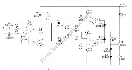
This true stereo indicator is different from what we usually find on FM radio receiver, which is usually a pilot tone detector. A stereo broadcast from FM radio station contain pilot tone, but a presence of pilot tone doesn’t necessarily a stereo broadcast signal since a mono FM transmitter ca broadcast pilot tone as well. Since this circuit detect the difference between left and right channel, this circuit can detect a real stereophonic programs. When there is no difference between R and L input signals, the output A1 and output A2 is at the same potential. That will make a a virtual ground rail at half the supply voltage. Here is the schematic diagram of the circuit:
(View)
View full Circuit Diagram | Comments | Reading(1442)
ZENER DIODE TESTER Circuit
Published:2013/3/5 21:05:00 Author:Ecco | Keyword: ZENER DIODE, TESTER
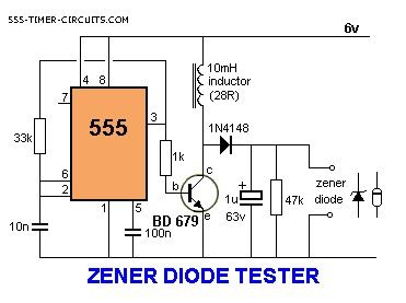
This circuit will test zener diodes up to 56v. See Talking Electronics website, left index, 200 Transistor Circuits (circuits 1-100) and go to Zener Diode (making) to see how to make a zener diode and how to create a zener voltage from a combination of zeners. Place the zener across the terminals in the circuit below and read the value across it with a multimeter set to 50v range.
(View)
View full Circuit Diagram | Comments | Reading(3745)
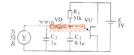
Non-contact AC measuring circuit
Published:2013/3/5 0:45:00 Author:Ecco | Keyword: Non-contact, AC, measuring circuit
Non-contact AC measuring circuit is shown as figrue.
(View)
View full Circuit Diagram | Comments | Reading(2552)
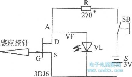
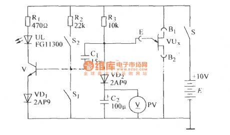
Photosensitive element test circuit
Published:2013/3/4 3:12:00 Author:Ecco | Keyword: Photosensitive element, test circuit
Photosensitive element test circuit is shown as figure.
(View)
View full Circuit Diagram | Comments | Reading(1249)
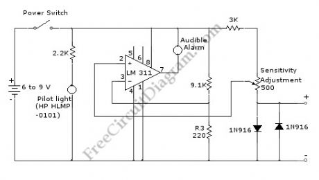
DARK DETECTOR Circuit
Published:2013/3/4 21:36:00 Author:Ecco | Keyword: DARK DETECTOR
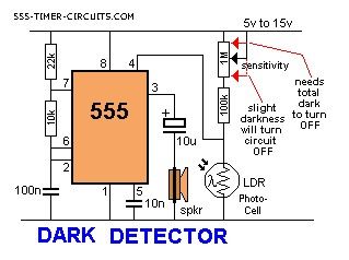
When the level of light on the photo-cell decreases, the 555 is activated. Photo-cells (Photo-resistors) have a wide range of specifications. Some cells go down to 100R in full sunlight while others only go down to 1k. Some have a HIGH resistance of between 1M and others are 10M in total darkness. For this circuit, the LOW resistance (the resistance in sunlight) is the critical value.More accurately, the value for a particular level of illumination, is the critical factor. The sensitivity pot adjusts the level at which the circuit turns on and allows almost any type of photo-cell to be used.
(View)
View full Circuit Diagram | Comments | Reading(2624)
CONTINUITY TESTER Circuit
Published:2013/3/4 21:35:00 Author:Ecco | Keyword: CONTINUITY TESTER
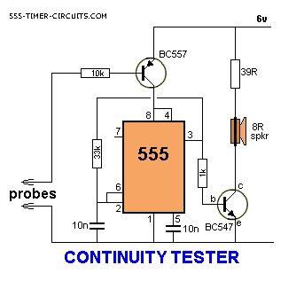
This circuit will detect low resistances and high resistances to produce a tone from the speaker. It will detect up to 200k and the circuit automatically turns off when the probes are not used.
(View)
View full Circuit Diagram | Comments | Reading(2662)
Single- junction transistor divider ratio measuring circuit
Published:2013/3/4 3:08:00 Author:Ecco | Keyword: Single- junction transistor, divider ratio , measuring
Single- junction transistor divider ratio measuring circuit is shown as figure.
(View)
View full Circuit Diagram | Comments | Reading(1009)
Reverse breakdown voltage test circuit
Published:2013/3/4 3:10:00 Author:Ecco | Keyword: Reverse , breakdown voltage, test circuit

Reverse breakdown voltage test circuit is shown as figure.
(View)
View full Circuit Diagram | Comments | Reading(1369)
The unijunction transistor speed measuring circuit 1
Published:2013/3/4 3:09:00 Author:Ecco | Keyword: unijunction transistor , speed measuring
The unijunction transistor speed measuring circuit 1 is shown as figure.
(View)
View full Circuit Diagram | Comments | Reading(1012)
The logic test circuit
Published:2013/2/28 1:18:00 Author:Ecco | Keyword: logic test
The logic test circuit is shown as figure.
(View)
View full Circuit Diagram | Comments | Reading(1124)
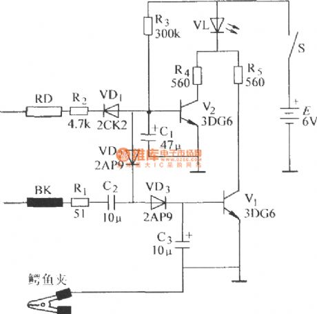
Speaker voice coil detection circuit
Published:2013/2/28 1:16:00 Author:Ecco | Keyword: Speaker, voice coil , detection circuit
Speaker voice coil detection circuit is shown as figure.
(View)
View full Circuit Diagram | Comments | Reading(1526)
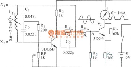
The quartz crystal oscillator test circuit diagram
Published:2013/2/28 1:15:00 Author:Ecco | Keyword: Quartz crystal oscillator, test circuit
The quartz crystal oscillator test circuit diagram is shown as figure.
(View)
View full Circuit Diagram | Comments | Reading(2706)
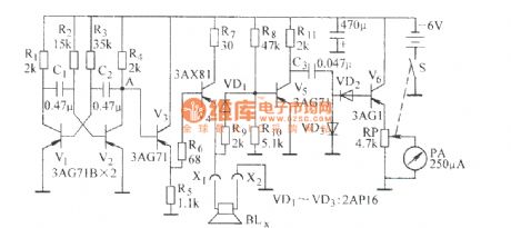
Local coil short-circuit test circuit
Published:2013/2/28 1:12:00 Author:Ecco | Keyword: Local , coil , short-circuit, test circuit
Local coil short-circuit test circuit is shown as figure.
(View)
View full Circuit Diagram | Comments | Reading(2424)
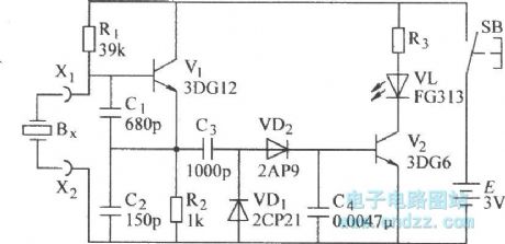
Fluid-Level Detector
Published:2013/2/27 20:55:00 Author:muriel | Keyword: Fluid-Level Detector
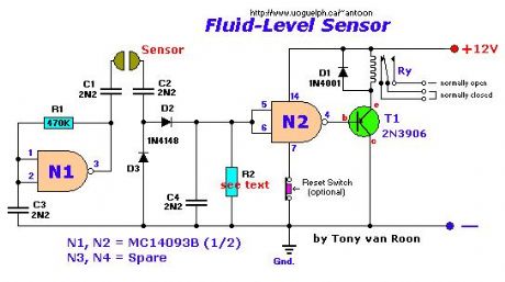
View full Circuit Diagram | Comments | Reading(1283)
Cut Phone Line Detectors
Published:2013/2/27 20:49:00 Author:muriel | Keyword: Cut Phone Line Detectors

View full Circuit Diagram | Comments | Reading(1072)
Crystal Tester, #3
Published:2013/2/27 20:47:00 Author:muriel | Keyword: Crystal Tester, #3
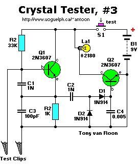
View full Circuit Diagram | Comments | Reading(1291)
| Pages:7/101 1234567891011121314151617181920Under 20 |
Circuit Categories
power supply circuit
Amplifier Circuit
Basic Circuit
LED and Light Circuit
Sensor Circuit
Signal Processing
Electrical Equipment Circuit
Control Circuit
Remote Control Circuit
A/D-D/A Converter Circuit
Audio Circuit
Measuring and Test Circuit
Communication Circuit
Computer-Related Circuit
555 Circuit
Automotive Circuit
Repairing Circuit