
Measuring and Test Circuit
Index 19
Level test circuit with TTL six NOT gate 7404
Published:2012/10/10 21:32:00 Author:Ecco | Keyword: Level test , TTL, six NOT gate
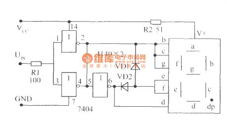
Because TTL ( CMOS ) circuit has determined high, low level input threshold voltage, it does not need additional set or adjust, and the result is very accurate. The two NAND gates of input end can be connected in parallel to increase drive capability, high level dispalys H, low level displays L. Due to they use common anode digital tube, VD1, VD2 polarity needs to be changed. If the CMOS level needs to be tested, you should use CMOS NAND gate circuit 4069.
(View)
View full Circuit Diagram | Comments | Reading(2124)
Metal Detector DIY Circuit
Published:2012/10/10 1:50:00 Author:muriel | Keyword: Metal Detector
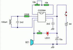
The heart of this diy metal detector circuit is CS209A. The metal detector it is build with one coil of 100uH. CS209A has one oscillator wich forms an LC circuit, the inductance of the coil will change when it is near metal objects.LED 1 will light and the buzzer turns on when the coil is changing inductance. The setup is easy, VR1 is adjusted ( away from any metal objects ) so that LED 1 will light and the buzzor sounds on, and then VR1 will be trimmed until led and buzzer are off.
DIY metal detector circuit
(View)
View full Circuit Diagram | Comments | Reading(2483)
Remote Tester Circuit
Published:2012/10/10 1:47:00 Author:muriel | Keyword: Remote Tester
A simple Remote tester to check all types of Remote hand sets…….
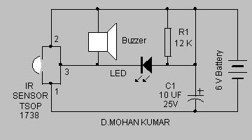
This simple remote tester can be a good tool to check whether a remote hand set is working or not. It uses the commonly available IR sensor TSOP 1738.The IR sensor has a PIN photodiode and an FET signal amplifier enclosed in an Epoxy case.
The sensor requires five volts for its operation and its output is active low. Normally its output gives + 5 volts and goes down to zero when it receives 38 KHz pulsed IR rays. When the remote handset is focused on to the sensor and any one button is pressed, buzzer beeps and LED blinks indicating that the handset is OK.
Remote Tester Circuit Diagram
(View)
View full Circuit Diagram | Comments | Reading(2341)
Water Level Indicator circuit
Published:2012/10/9 2:36:00 Author:muriel | Keyword: Water Level, Indicator
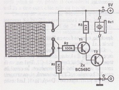
This simple water level indicator will activate a buzzer in order to make a noise when a certain level of water is being reached. Because the water sensor and the command circuit are located on the same printed circuit board, indicator, together with its 9 V battery and the buzzer can be mounted in a compact case. Obviously the sensor, that is made by corossion, on the board, must not be mounted directly on iron or steel bathtubs but with a magnet atached on the case. Check out the new water level sensor circuit.
Water Level Indicator Circuit Diagram
In order to avoid the scratching of the bathtub, the magnet can be covered with plastic or rubber. If the bathtub is made of polypropylene, the water indicator must be attached to it with two clamps or double adhesive tape.
When the water reaches the sensor T1 base is connected to the positive terminal. In consequence, T1 and T2 are opening and the buzzer it makes a buzz. The current consumption is now around 25 mA.
In order that the water level sensor circuit will not be put into operation by steam it may be necessary the reduction of the sensibility by increasing the value of R2. Is recommended to tin the PCB in order to avoid corossion.
Water Level Indicator PCB Layout
(View)
View full Circuit Diagram | Comments | Reading(2853)
Reflex Tester Circuit
Published:2012/10/9 2:28:00 Author:muriel | Keyword: Reflex Tester
Testing human reaction speed is not only a fun way of spending time, but also allows the drawing of conclusions, for example on the skills of a momentary driver. When the contact closes the power button, the astabil multivibrator built with IC1 produces pulses that are applied to counter IC3. D1 …. D10 LEDs light up sequentially in a chained fast.Once the person tested acts stop button S2 the astabil multivibrator is blocked, the last ordered with decoder IC4 LED lights next. If frequency of the astabil multivibrator with P1 is adjusted so that the numerator, for example, receives a pulse every 10 seconds, then the reaction time can be read easily. The test can be repeated after drive reset button (S3). Reflex tester circuit absorbs about 120 mA current, supply voltage (5V) must be stabilized. Frequency can be adjusted to the astabil multivibrator with P1 between 10 Hz and 80 Hz.
Reflex Test Circuit Diagram
(View)
View full Circuit Diagram | Comments | Reading(1361)
Mobile Scanner Circuit
Published:2012/10/8 2:45:00 Author:muriel | Keyword: Mobile Scanner
Here is a device to locate the mobile phone. It emits intermittent flashes and beeps to indicate the presence of an active mobile phone. The circuit becomes active even if the mobile phone is in silent mode. It can be used to detect mobile phone call in noisy environments. Range of the circuit is 15 cm.The circuit is basically an RF detector. During the activation of mobile phone, strong RF field will be generated. The sensor coil L detects the RF signals and T1 amplifies the signals. The amplified signals are given to the clock input of IC1. CD 4017 is a Johnson decade counter IC with 10 outputs. Its clock input pin 14 is highly sensitive to RF pulses so that it is a very good choice for RF detection. Only two outputs (Q1 andQ2) of the IC are used while the Q3output is tied to the reset pin 15 so that IC will reset on every third pulse.
This will repeat the activation of LED and Buzzer. When the sensor detects the RF signal, clock input of IC1 gets pulses and its output pins 2 and 4 becomes high and low alternately giving flashing lights and beeps. The coil used in the circuit is a ready made inductor.Buzzer used is a small piezo buzzer.
Mobile Scanner Circuit diagram
(View)
View full Circuit Diagram | Comments | Reading(1932)
GigaHertz Signal Detector circuit
Published:2012/10/8 2:41:00 Author:muriel | Keyword: GigaHertz, Signal Detector
This circuit is useful to detect microwave (gigahertz signal) sources like microwave oven, satellite communication devices, Mobile phones etc. It gives audio visual indications when it detects the Microwaves in the Gigahertz band.Microwave is the form of EM radiation with frequencies between 2 GHz and 300 GHz. Microwave oven uses UHF around 3 GHz in the S band. Mobile phones and Satellite devices generally use 2 to 3.5 Gigahertz signals. The circuit exploits a few simple scientific facts about EM radiations and Magnetic induction. Electromagnetic radiation has both electrical and magnetic field components which oscillate in phase perpendicular to each other to the direction of energy propagation.
If an inductor coil with a parallel capacitor is placed in the path of EM radiation, the capacitor stores electrical energy and inductor stores energy in the magnetic field induced by the coil windings. The magnetic field induces a current in the inductor through’ Skin Effect’. This phenomenon is exploited in the circuit to detect the energetic microwave radiations. A pickup coil (L2) with a capacitor (C2) forms the signal detector which resonates in response to the microwave radiation and generates a minute voltage (around 2 milli volts) along the signal diodes D1 and D2.
Since the voltage generated by the sensor assembly is too weak, a differential amplifier (IC1) is used to amplify the signal.CA 3130 (IC1) is designed as a differential amplifier with balanced inputs set by R1 and the sensor assembly. The pickup coil is directly coupled to the inverting and non inverting inputs of IC1, so that a minute current in the pickup coil can generate a potential difference across the inputs of IC1 and its output switches high.
GHz Signal Detector Circuit Diagram
CA 3130 ( IC1) is a CMOS version high speed switching Operational amplifier with gate protected p- channel MOSFET transistors in the inputs. This makes the IC suitable to switch the output high with a current as low as 2 pA. VR is provided for the offset adjustment and bias the internal circuitry of the IC1, so that its output is ordinarily held low. Resistor R3 gives some negative feed back to the amplifier.
When the bursts of microwave impinge on the Loop aerial (L1, it pickup the energy from the radiation and transfer it to the inductor coil (L2) This creates an alternating current in the inductor which passes to the inputs of IC1 through C1 and D1.
Signal diodes D1 and D2 (BAT 43 Shottky Diodes) directs the induced current into the inputs of IC1 and the capacitor C3 provides suitable stabilization of the non inverting input of IC1. Diodes D1 and D2 also perform the function of signal detection. Normally the inputs of IC1 are biased by R1 and C2, and its output is set low by VR. When there is a microwave radiation near the sensor coil, it generates a current that upsets the balance in the inputs of IC1 and its output switches high to drive the switching transistor T1.
Buzzer starts sounding and LED lights indicating the presence of Microwave. Sensor assembly is the important part of the circuit and should be prepared carefully. L2 can be a miniature coil with ferrite core. This can be procured from an old CFL. L1 is the common dipole TV antenna. When the circuit is first powered up, VR needs adjustments to keep the buzzer and LED off. The circuit is immune to other forms of RF radiations but can detect the Giga Hertz signals from an active mobile phone. (View)
View full Circuit Diagram | Comments | Reading(2263)
Temperature Meter circuit
Published:2012/10/8 2:39:00 Author:muriel | Keyword: Temperature Meter
This temperature meter uses the precision micro power centigrade sensor IC LM35. The output voltage of the IC is linearly equal to +10Mv per degree centigrade. The temperature level is displayed through LED readout. The circuit uses the precision temperature IC LM35. This three pin transistor like IC give output linearly equal to +10mV per degree rise in temperature. It can measure temperature between -4 degree to +110 degree centigrade. Its related type LM34 is Fahrenheit sensor and its output is equal to -10mV per degree Fahrenheit. Output of IC1 is directly given into the input of the display driver IC LM3914. It is a monolithic integrated circuit with 10 active low outputs that can drive 10 LEDs directly without a current limiting resistor.
The internal circuitry of the IC adjusts the current passing through the LEDs. The input of LM 3914 is very sensitive and its outputs 18 – 10 sinks current one by one as the input receives an increment of 125 milli volts. Here only 6 outputs are used to drive 6 LEDs. More LEDs can be included in the remaining outputs if required. As the IC LM35 senses temperature rise, LEDs one to six light up. If the sensitivity is not high, VR2 can be omitted. Then output of IC1 should be directly connected to the input of IC2
Temperature Meter Circuit diagram
Calibration
When power is applied, some of the LEDs will glow. Calibrate the circuit by giving different temperature to IC1. For this a thermometer and hot water of different temperature is required. Sock some cotton with warm water of around 37degree (normal room temperature) and gently make contact with IC1. Adjust VR1and VR2, till LED1 glows.
IC LM35 and LM3914
ICLM35 and LM 3914 Pin out
(View)
View full Circuit Diagram | Comments | Reading(1775)
Lithium battery cell tester circuit
Published:2012/9/28 21:03:00 Author:muriel | Keyword: Lithium battery cell, tester
3 Volt Lithium Cells are extensively used in low power applications such as Digital clocks, Toys etc. These are also used in Computer Mother boards as backup power source to keep the memory. The circuit described here is a handy tester to check the voltage level in the used Lithium cell before throwing it away.Even if it carries less than 2 volts, it can be used again in some very low power applications that require less than two volts.The circuit uses an LED as a Zener diode to give 2.2 V reference voltage to compare the voltage level in the Lithium cell.IC1 (TL071) is used as a Voltage comparator. The low noise JFET Operational Amplifier TL071 is used in the circuit since it requires very low input bias current. Its inverting input is connected to the junction between R2 and a Green LED. Here LED is used like a Zener diode to give 2.2 V (Forward voltage of Green LED) as reference voltage.This LED has dual function. It act as a power on indicator as well as low value Zener which is not commonly available.
The non inverting input of IC1 receives voltage from the Lithium battery under test. When the non inverting input is not connected to the battery, output of IC1 will be low since its inverting input gets higher voltage than non inverting input. The low output from IC1 keeps T1 non conducting and the Green half of the Bicolour LED remains off.At the same time the high voltage in the collector of T1 gives base bias to T2 and it conducts. The Red half of the bicolour LED lights.
Lithium Cell Tester Circuit diagram
When a Lithium battery is connected to test points, the non inverting input of IC1 gets higher voltage (more than 2.2 volts) and the output of the comparator swings high. This makes T1 conducting and Green half of Bicolour LED lights indicating that the battery under test is holding more than 2.2 volts. At the same time T2 turns off since its base goes to ground potential. Red LED remains off in this state. In short, Green LED lights if the battery holds more than 2.2 volts.
TL071 and BC548 Pin Connections
Lithium battery cell
(View)
View full Circuit Diagram | Comments | Reading(1599)
Voltage and Current Tester
Published:2012/9/28 21:00:00 Author:muriel | Keyword: Voltage, Current, Tester
This Simple Voltage and Current tester can be used to measure the forward Voltage drop and current through Semiconductor Diodes like LED, Infrared diode, Photo diodes, Silicon diodes etc. This is ideal to assess the voltage and current drops through these devices during circuit design and calculating the power consumption in a particular section of the circuit. Different types of LEDs including power LEDs are now used in various applications. The voltage rating of these devices range between 1.8 to 5 volts. Current rating also varies from 20 mA to 50 mA. So by assessing the actual voltage and current consumption, it is easy to get full brightness without damaging the device. This will also prevents the unnecessary heating of these delicate devices and their breakdown
Voltage and Current Tester circuit
The circuit is a current regulator using the Darlington PNP transistor BD 140. It provides 9 volts and around 50 mA current to the device under test. Switch S1 is used to select the Voltage and current measurement. If S1 is placed in position 1, the circuit measures the current drop across the device under test. A 100 mA meter is placed in series with the current path. So that when the device is connected to point A and B, meter shows the current flowing through the device
When S1 is placed in position 2 and the device is connected to points A and B, voltage drop in the device can be measured. The 0-30 Volt meter is connected parallel to the device under test. So that it can give the voltage drop across the device.
Since diodes are One-way conductors, observe polarity while connecting to points A and B. Anode should be in A and Cathode in B. Connect small Alligator Clips to points A and B to hold the device under test.
Volt and Ampere Meter
Types of Diodes
(View)
View full Circuit Diagram | Comments | Reading(1952)
Improved Infrared Detector circuit
Published:2012/9/28 21:00:00 Author:muriel | Keyword: Improved, Infrared Detector

This improved infrared detector is specifically intended for use with commercial IR remote control handsets. This little circuit is useful for quick go/no-go testing of just about any remote control transmitting Infrared (IR) light signal. The key component of the IR detector is a sensitive photo transistor 2N5777. All infrared remote controls transmit pulse bursts. The photo transistor detects the modulated IR signal from the remote control handset under test and its output is processed by next BC557 and fed to the final LED driver transistor BC557. As a result the red LED in the circuit starts blinking in tune with the received signal. Please note that the LED lights up constantly when day light or other source of continuos IR light is detected.
Infrared Detector Circuit Diagram
The infrared detector circuit may be powered by just about any standard 9V compact battery or a wall adaptor capable of supplying 9VDC at about 100mA.The only setting up required is to adjust the 100K variable resistor.The construction drawing shows how the circuit may be cased in a small ABS case.
Block Diagram of the IR detector
(View)
View full Circuit Diagram | Comments | Reading(1967)
Numeric Water Level Indicator circuit
Published:2012/9/28 20:49:00 Author:muriel | Keyword: Numeric, Water Level Indicator

Most water-level indicators for water tanks are based upon the number of LEDs that glow to indicate the corresponding level of water in the container. Here we present a digital version of the water-level indicator. It uses a 7-segment display to show the water level in numeric form from 0 to 9.The numeric water level indicator circuit works off 5V regulated power supply. It is built around priority encoder IC 74HC147 (IC1), BCD-to-7-segment decoder IC CD4511 (IC2), 7-segment display LTS543 (DIS1) and a few discrete components.
When the water tank is empty, all the inputs of IC1 remain high. As a result, its output also remains high, making all the inputs of IC2 low. Display LTS543 at this stage shows ‘0,’ which means the tank is empty. Similarly, when the water level reaches L-1 position, the display shows ‘1,’ and when the water level reaches L-8 position, the display shows ‘8.’ Finally, when the tank is full, all the inputs of IC1 become low and its output goes low to make all the inputs of IC2 high. Display LTS543 now shows ‘9,’ which means the tank is full.
Assemble the numeric water level circuit on a general-purpose PCB and enclose in a box. Mount 7-segment LTS543 on the front panel of the box. For sensors L-1 though L-9 and ground, use corrosion free conductive-metal (stainless-steel) strips.Source: Electronics For You Magazine
Numeric Water-Level Indicator Circuit Diagram
(View)
View full Circuit Diagram | Comments | Reading(3784)
InfraRed Remote Control Tester
Published:2012/9/26 21:17:00 Author:muriel | Keyword: InfraRed, Remote Control, Tester
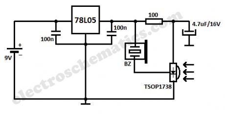
This small InfraRed Remote Control Tester circuit is used for checking the operation of an infrared remote control unit. The circuit is based on the idea of connecting a piezo buzzer directly to an IR receiver IC.Operation of the remote control is indicated by the buzzer making a chattering noise. The circuit is very sensitive and has a range of several metres.The TSOP1738 integrated IR receiver accepts, amplifies and demodulates the IR signal from the remote control, producing an output with a frequency of around 700 Hz. The piezo buzzer is connected to its output, rendering the signal audible. All the other components are simply concerned with producing a stable 5 V power supply from the 9 V PP3-(6F22) type battery.
Instead of the TSOP1738 similar devices from other manufacturers can be used, and of course carrier frequencies other than 38 kHz can be used. The circuit still works if there is a mismatch between the nominal carrier frequencies of the transmitter and receiver IC, but range is reduced. It is still, however, adequate for determining whether a remote control is producing an IR signal or not.
IR Remote Tester Circuit Diagram
(View)
View full Circuit Diagram | Comments | Reading(0)
Vibration Sensor/Detector circuit
Published:2012/9/25 21:37:00 Author:muriel | Keyword: Vibration Sensor,Detector

With the help of a simple ceramic piezo-electric detector it is possible to assemble an interesting and useful Impact sensor unit,which can be used to detect impact and vibration on doors, showcases, windows etc. The shock sensor (Ceramic piezo-electric detector) uses a “unimorph” diaphram, which consists of a piezo-electric ceramic disk laminated to a metal disk. The sensor supplies a voltage proportional to the acceleration of the impact or vibration, for example 40mV/G ie output is near 2V for 60G impact.Here a low voltage, low current Impact sensor unit is realised using a standard ceramic piezo-electric detector which drives a monostable multivibrator (IC1) circuit to activate a npn silicon transistor (T1). Open collector output of this transistor switch can be interfaced to an external alarm/switch circuit for further processing. Since current consumption of the circuit is very low (from 5 to 6 mA only) any common 3V button cell can be used to power the sensor unit.When an impact is sensed, the monostable drives the transistor switch to ON , for a finite duration determined by the incircuit values of RC timing components R3 and C2.
The M74HC123 (IC1) is an high speed DUAL retriggerable CMOS MONOSTABLE MULTIVIBRATOR (MMV) fabricated with silicon gate C2MOS technology, with all inputs protected against static discharge and transient excess voltage. There are two trigger inputs, negative edge and positive edge. Here, only one monostable part with positive edge triggering (pin 2) is used. After triggering, the output maintains the monostable state for the time period determined by the external resistor R3 and capacitor C2.
Vibration/Impact Sensor Circuit Schematic
(View)
View full Circuit Diagram | Comments | Reading(2104)
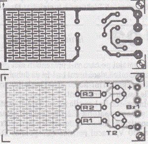
Network RJ45 Cable Tester circuit
Published:2012/9/25 21:36:00 Author:muriel | Keyword: Network, RJ45, Cable Tester
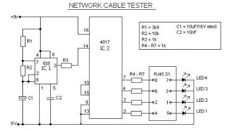
This is a multifunction RJ45 network cable tester. It is the design of the network cable (RJ45) test, and telephone (RJ11). It is cheap and easy to use. It works for network, telephone, cable with RJ45 half “Registered Jack” plug immediately indicate whether a crossover network cable or straight, flashing a yellow or green LED. If something is broken or if you press the button, the tester is in line with the wire test. How does the network cable tester circuit work?The top RJ45 connector sends signals to each of its eight legs. The lower RJ45 connector receives signals from the top RJ45 connector created by the wire.
When the red LED above the orange light LED bar shows the pins in the top RJ45 connector sends a test signal, and when the bottom of the red LED illuminates orange LED bar indicates which of the eight dioceses of the bottom RJ45 connector signal receives in this state where the wire is broken or not connected, none of LEDs in the LED bar will light up orange.
If a short circuit between two or more wires, more than an orange LED lights up when the bottom red LED lights. Each time the button is the active output pin.RJ45 Cable Tester Specifications
For network cable (RJ45) and telephone (RJ11) tests.
Similar test can double-twisted cables 1,2,3,4,5,6,7,8 and Ground, meanwhile, can judge wrong connection, short circuit and open circuit.
ON / OFF button.
With four LED indicator.
Composing the master and remote two tests that can take a role in the testing easier.
Power by 9V battery.
Compact, durable design with a black plastic bag with zipper for storage.
Cable RJ45 network and RJ11 phone port
RJ45 Network Cable Tester Circuit Schematic
(View)
View full Circuit Diagram | Comments | Reading(2859)
LED Scanner circuit
Published:2012/9/25 0:50:00 Author:muriel | Keyword: LED,Scanner
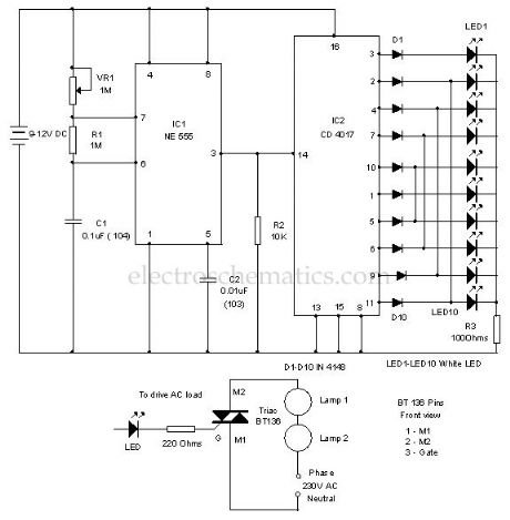
Here is a simple LED chaser simulating a scanner through the back and forth light effect. It used high bright White LEDs to give the chaser effect. The circuit uses an oscillator to produce fast pulses and a decade counter to drive the LEDs.IC1 is designed as an astable multivibrator to give continuous positive pulses to the decade counter. Variable resistor VR1, R1 and C1 form the timing components. By adjusting VR1, it is possible to change the speed of the scanning LEDs.
Output pulses from IC1 are fed to the clock input of the decade counter IC2. Resistor R2 keeps the clock input of IC2 low after each positive to negative transitions of input pulses. This is necessary because sometimes the clock input of the decade counter stays positive and does not accept input pulses.
LED Scanner Circuit
Note: This circuit can be used to drive AC loads like 60 watts bulbs for decoration purpose. For that slight modification is necessary. Connect the cathode of LED to the gate of a Triac (BT136) through a 220 ohms resistor. Connect bulb to the M2 pin of triac in series with the phase line as shown in the diagram. Six 60 watts bulbs can be connected serially to each triac (BT136 is rated to 400 watts). (View)
View full Circuit Diagram | Comments | Reading(2195)
Keyhole Finder circuit
Published:2012/9/24 4:24:00 Author:muriel | Keyword: Keyhole,Finder

This 3 volt Lithium cell operated LED flasher can be used as a key hole finder in darkness. A small lithium button cell can power the circuit more than 6 months continuously with day and night flashes. The circuit can also be used in key stand to search key in darkness.
The circuit is a simple oscillator comprising two complementary transistors BC 547 and BC557. These NPN and PNP transistors are wired as a simple oscillator with components C1 and R1 so that the LED flashes based on the charging and discharging of C1. Current consumption of LED is very low so that a normal 3 volt lithium battery can power the circuit for long time. A miniature 12 volt battery used in Car remote can power the circuit more than 2 years continuously.
Keyhole Finder Circuit
Use a high bright transparent 5 mm Yellow LED and fix the unit near the keyhole.?
7 Responses to “Keyhole Finder circuit”
(View)
View full Circuit Diagram | Comments | Reading(2733)
Quartz 1Hz Timebase
Published:2012/9/24 4:21:00 Author:muriel | Keyword: Quartz,1Hz, 1Hz

Here is one basic circuit of a simple but accurate 1Hz timebase generator built around a standard Quartz clock circuit board. Just lift the clock PCB from any cheap quartz clock and carefully remove all extra components like the drive coil, buzzer, alarm switch and clock mechanism (quartz movement), etc.Next wire the circuit as shown in the schematic diagram, observing correct connection points and polarities, and power it from a 5VDC supply. Precision 1Hz clock signal generator is now ready to serve you. With suitable modification(s) at the output you can use this circuit to drive blinkers, beepers and microcontroller based ciruits.
Notes:
1. Stable 1.5-1.6 VDC supply for the clock PCB is derived from the 5VDC input supply with the help of componets R1, D1 and C1. Only use a 10mm Red color (Vf=1.6V) LED for D3.
2. Drive coil outputs (L1&L2) of the clock PCB are joined together to get one second pulse output with the help of two schottky diodes (D1&D2). Such low-drop diodes are crucial for this circuit.
3. The circuit is inverting output type and hence, the output is normally at high level,and pulses low once a second.By adding a second (optional) transistor, this can be reversed, ie non inverting, so that the output is normally at low level, and pulses high once a second.
Quartz 1Hz Timebase Generator Circuit Schematic
?
4 Responses to “Quartz 1Hz Timebase”
(View)
View full Circuit Diagram | Comments | Reading(4427)
DIY Infrared Radar System
Published:2012/9/24 4:17:00 Author:muriel | Keyword: DIY, Infrared, Radar System

Chris from PyroElectro.com has a great article about a do-it-yourself radar system build with PIC18F452. It’s a great hobby project although the schematic is very complicated. This project uses three main devices to create the personal radar system.The IR Range sensor gives output, the pic microcontroller processes it and then displays the output on the led array. The goal of this project is to create a working ir radar system. The system will only be required to measure close proximity at an angle of 90 degrees as seen in the example above. The range of system is roughly 4-30cm, 20-150cm & 1m-5.5m depending upon which sensor you choose to use.
Below is an example of what short range personal radar could be used for.
DIY Infrared Radar Circuit Schematic
Source: http://www.pyroelectro.com/projects/ir_radar/?
5 Responses to “DIY Infrared Radar System”
(View)
View full Circuit Diagram | Comments | Reading(1592)
Electronic Lie Detector Circuit
Published:2012/9/24 4:14:00 Author:muriel | Keyword: Electronic, Lie Detector

This electronic lie detector circuit will give two readings: one for difficult questions for the subject and another to show its emotional state in general.The emotional states are detected not only by heart beat accelaration and trembling hands but also an increase in skin humidity whose resistance decreases causing the entry into operation of the lie detector.Two electrodes can be used as a flexible wire, bare, wrapped around fingers or wrist.In order to not influence the measurement result the device must be powered from two 9 Volts batteries.
Each change in resistance, and therefore the voltage at the input circuit will be amplified by operational amplifier A1, which also serves as separator. The output signal will determine, by R3, a deviation of the measuring instrument.
General emotional state of a person can be assessed by measuring the average resistance of the skin over a period of time. The indication is provided by an indicator instrument connected to point B of the circuit. Operational amplifier A2 is connected as an integrator and allows the circuit to automatically adjust according to the average resistance of the skin.
Length of time to measure the skin resistance is determined by R5, C2 and C3. Until such time elapses, the lie detector gives no indication although diodes D1 and D3 provide a rapid response of the circuit.
Human skin lie detector schematic
Potentiometer P1 allows you to adjust the time delay of the circuit. Since skin resistance varies from one person to another, may be necessary to change the resistance value R1. This resistance can be replaced with a potentiometer.
Reading a great value to the instrument connected to the output of B indicates that subject’s skin resistance is low (which is a characteristic of people with sticky hands) and it is advisable to reduce the value of R1.
lie detector components listR1 = 47KR2 = 1MR3 = 3.3KR4 = 10KR5 = 10MP1 = 10KC1 = 100nC2 = C3 = 470nD1 = D2 = 1N4148IC1 = IC2 = LF356?
14 Responses to “Electronic Lie Detector Circuit”
(View)
View full Circuit Diagram | Comments | Reading(1305)
| Pages:19/101 1234567891011121314151617181920Under 20 |
Circuit Categories
power supply circuit
Amplifier Circuit
Basic Circuit
LED and Light Circuit
Sensor Circuit
Signal Processing
Electrical Equipment Circuit
Control Circuit
Remote Control Circuit
A/D-D/A Converter Circuit
Audio Circuit
Measuring and Test Circuit
Communication Circuit
Computer-Related Circuit
555 Circuit
Automotive Circuit
Repairing Circuit