
Measuring and Test Circuit
Index 100
Circuit Of BA1404/1404F FM Stereo Transmitter
Published:2011/4/20 22:05:00 Author:TaoXi | Keyword: FM Stereo, FM Stereo Transmitter
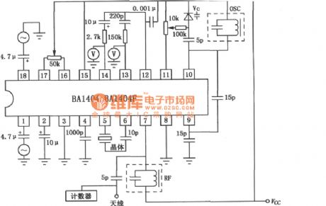
The Circuit Of BA1404/1404F FM Stereo Transmitter is as shown. (View)
View full Circuit Diagram | Comments | Reading(2213)
Circuit of Encryption Wireless TV
Published:2011/4/20 7:52:00 Author:TaoXi | Keyword: Encryption, Wireless, TV
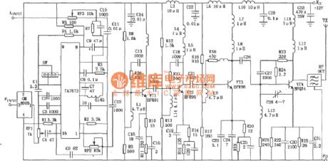
The circuit of encryption wireless TV with 1W transmit power is as shown. The input signal are audio and video signals, and the launch channel is decided by the SW SAW resonator in modulation circuit. Video signal that sent by the cameras, video recorders, VCD and other equipment will transport into the 3-pin of the encryption module of the transmitter, then output the encrypted video signal, and modulated in to the RF signals by modulation circuit, VT1, VT2 voltage amplification, VT3 promote amplification, VT4 power amplifier, at last launch out by the antenna. Because of the VTl ~ VT4 is amplified by broadband (46~870MHz), so between the power amplifier and antenna band-pass filter need to use the bandpass filter to prevent the band emissions.
The decryption receiver is composed of TDQ-3 tuner, finished TA7680 board and the decryption module, as shown in the figure. Receiver receives the transmitted signal, converses the frequency in high-frequency tuner, and outputs the 38MHz IF signal, outputs audio signal and the encrypted video signal, and after decrypted by the decryption module 8910, we get the video signal to watch. (View)
View full Circuit Diagram | Comments | Reading(1843)
Ultrasonic Transmitter and Receiver Circuit
Published:2011/4/20 8:02:00 Author:TaoXi | Keyword: Ultrasonic, Transmitter, Receiver
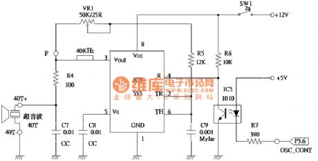
The Ultrasonic Transmitter and Receiver Circuit is as shown. (View)
View full Circuit Diagram | Comments | Reading(1616)
Digital pulse width measurement circuit composed of CD4518 and CD4069
Published:2011/3/28 1:53:00 Author:may | Keyword: Digital pulse width measurement

Digital pulse width measurement circuit is show in the diagram. It adopts a 100KHz reference frequency, count at the range of measured signal pulse width, the product of count value and resolving capability present measured signal pulse width value, display through four digital seven-segment LED. The resolving capability is 10μs, its maximum measure width is 99.99ms. IC2, IC3 is double BCD up counter CD4518; IC4~IC7 is BCD seven-segment latch/ decoder/ driver CD4511.
(View)
View full Circuit Diagram | Comments | Reading(8492)
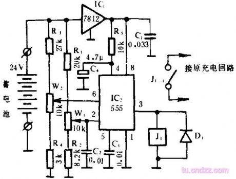
Uninterruptible power supply storage battery voltage monitor circuit
Published:2011/3/31 2:09:00 Author:may | Keyword: Uninterruptible power supply, storage battery, voltage monitor
View full Circuit Diagram | Comments | Reading(740)
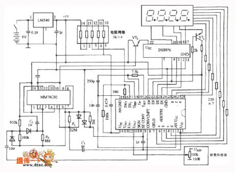
Testing circuit of moving objects along production line conveyer belt
Published:2011/4/14 21:10:00 Author:Nicole | Keyword: moving object, production line, conveyer belt
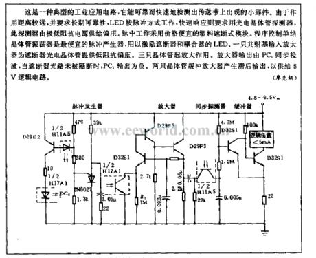
It is a typical industry application circuit, it can test the small components in conveyer belt reliably and fast. Because of the distance, and it needs long-term reliability, so LED works with pulse, it needs fast response so we should use phototransistor detector, high-low impedance power supply will provide this detector with bias. Pulse working adopts cheap plastic obstruction model. Program control unijunction transistor oscillator is the cheapest pulse generator, it is used to inspire governor's and coupler's LED. A common emitter input amplifier supply low impedance to governor phototransistor. Three transistors play a role of amplifying. Amplifier output is tested by PC1, when governor light load is not cut off, PC1 output is negative. Two transistors buffer amplifier then it produces delay output, to supply to 5V logic circuit. (View)
View full Circuit Diagram | Comments | Reading(656)
Sonification photodetector circuit
Published:2011/4/15 1:10:00 Author:Nicole | Keyword: photodetector
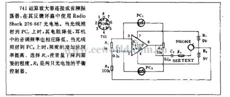
741 operation amplifier is connected to audio oscilaltor, using Radio Shack 276-667 photoelectric cell in feedback loop. When the light shine on PC1, the resistance decreases, the earphone tone frequency declines too. When the light shine on PC2, the increasing illuminance makes the frequency rise. Selecting R4 can make the volume drop to needed degree. R3 is a balance controller of two photoelectric cells. (View)
View full Circuit Diagram | Comments | Reading(565)
18V observation circuit
Published:2011/4/1 20:26:00 Author:may | Keyword: 18V, observation
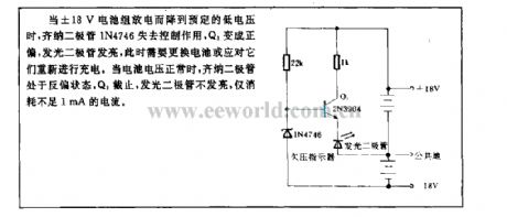
When ±18V battery pack discharge and drop to preconcerted low voltage, Zener diode 1N476 lose control function, Q1 become forward bias, LED is shine. At this time we need to replace the batteries or recharge to them. When battery voltage is normal, Zener diode is in reversal of biasing state, Q1 is cut-off, LED fails to shine, it only consumes current less than 1mA.
(View)
View full Circuit Diagram | Comments | Reading(736)
Capacitor measuring circuit diagram
Published:2011/3/20 22:50:00 Author:Ecco | Keyword: Capacitor
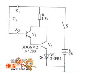
Capacitor measuring circuit diagram is as below:
(View)
View full Circuit Diagram | Comments | Reading(720)
Numeric electronic scale circuit diagram
Published:2011/3/27 20:33:00 Author:Ecco | Keyword: Numeric ectronic scale
Numeric electronic scale circuit diagram
(View)
View full Circuit Diagram | Comments | Reading(2683)
The circuit diagram of electric energy meter with ADE7752
Published:2011/3/24 3:43:00 Author:Ecco | Keyword: electric energy meter
The circuit diagram of electric energy meter with ADE7752: (View)
View full Circuit Diagram | Comments | Reading(3354)
Double functions water quality detection circuit
Published:2011/4/11 1:39:00 Author:Nicole | Keyword: double functions, water quality detection

The circuit adopts LM324. Adjusting W1 to make the output voltage of A1 change with light intensity between 0~4V. Probe T is two sheetmetals, put them into water, the resistance between them will change with the quantity of ions in water, A2 output changes too, it is adjusted by W2. A3, A4 form window comparator, W3, W4 decide window range. When VA4-<VA3+, VB<VA4-, F is 0 , E is 1 , D4 is red light; when VA4-<VB<VA3+, E=F= 1 , D is orange light; when VA3+<VB, E= 0 , F= 1 , D4 is green light. (View)
View full Circuit Diagram | Comments | Reading(753)
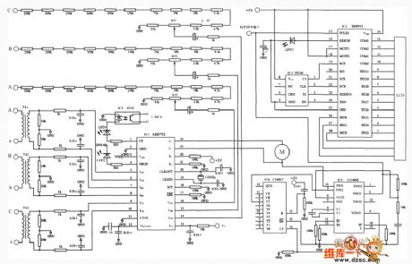
The ADE7752 circuit diagram with the three-phase four-wire system star connection(The three phase electric energy calculates system)
Published:2011/3/29 2:32:00 Author:Ecco | Keyword: The three phase electric energy calculates system
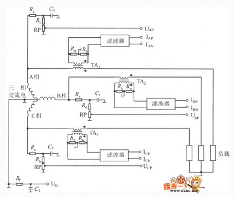
Three phase connecting law's including three phase three wires systems and three phases is four wires systems.The ADE7752 telephoneses that adopt three phase four wires system star polygon connecting laws is shown as chart. (View)
View full Circuit Diagram | Comments | Reading(1294)
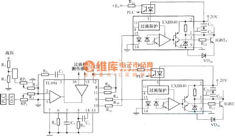
EXB series driver detection circuit
Published:2011/4/8 2:23:00 Author:may | Keyword: driver, detection
View full Circuit Diagram | Comments | Reading(610)
EXB841 testing input and output waveform circuit
Published:2011/4/8 2:14:00 Author:may | Keyword: testing, input and output waveform
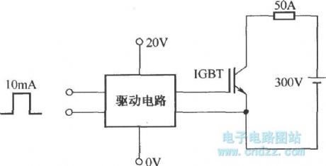
View full Circuit Diagram | Comments | Reading(878)
EXB841 testing over current waveform circuit
Published:2011/4/8 2:12:00 Author:may | Keyword: testing, over current waveform
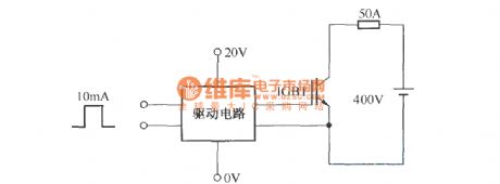
View full Circuit Diagram | Comments | Reading(746)
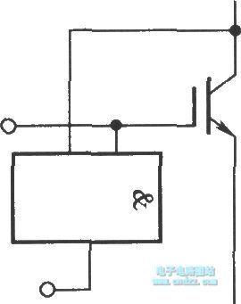
IGBT collector over current detection circuit
Published:2011/4/8 1:13:00 Author:may | Keyword: IGBT, collector, over current detection
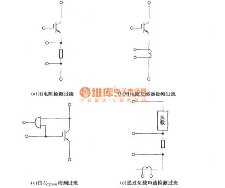
(a) using resistor to detect over current
(b) using current transformer to detect over current
(c) detect over current by UCE(sat)
(d) through load current to detect over current (View)
View full Circuit Diagram | Comments | Reading(1800)
The circuit testing the input and output waveform of XB850
Published:2011/4/2 3:47:00 Author:may | Keyword: input and output waveform, testing
View full Circuit Diagram | Comments | Reading(637)
PI adjustor circuit diagram
Published:2011/4/6 4:50:00 Author:may | Keyword: PI adjustor
View full Circuit Diagram | Comments | Reading(638)
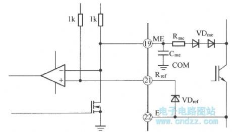
IGBT UCE voltage monitor principle
Published:2011/4/6 4:36:00 Author:may | Keyword: IGBT UCE, voltage monitor
View full Circuit Diagram | Comments | Reading(934)
| Pages:100/101 At 2081828384858687888990919293949596979899100Under 20 |
Circuit Categories
power supply circuit
Amplifier Circuit
Basic Circuit
LED and Light Circuit
Sensor Circuit
Signal Processing
Electrical Equipment Circuit
Control Circuit
Remote Control Circuit
A/D-D/A Converter Circuit
Audio Circuit
Measuring and Test Circuit
Communication Circuit
Computer-Related Circuit
555 Circuit
Automotive Circuit
Repairing Circuit