
Measuring and Test Circuit
Index 86
CRYSTAL_TESTER
Published:2009/6/15 21:19:00 Author:May
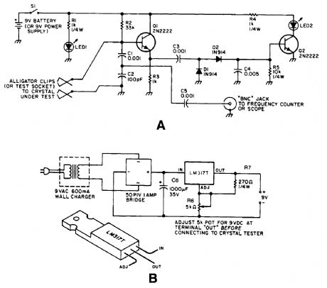
Q1 acts as a Colpitts crystal oscillator, and if the crystal under test is operational, the RF signal is rectified by D1 and D2, turning on Q2 and lighting indicator LED2. LED1 is a power indicator. (View)
View full Circuit Diagram | Comments | Reading(3936)
EASY_CRYSTAL_IMPEDANCE_CHECKER
Published:2009/6/15 21:06:00 Author:May
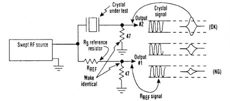
On occasion, micropro c es s ors/micro c omputers and microprocessor crystals just aren't compati-ble with each other. Many microprocessor data sheets specify maximum values for a crystal's equiv-alent series resistance (RS) that aren't met by some crystals advertised for microprocessor/ microcomputer use. As a result, a crystal with an RSvalue greater than the maximum specified for the chip might cause problems, such as a balky or even inoperative clock oscillator.To tackle this problem, a suspected crystal can be given a quick check forRS with a simple test setup that consists of a sweep generator, oscilloscope, and three resistors (see the figure). When the frequency source is brought to the crystal's frequency, output 2 will maximize. If it exceeds the am-plitude of output 1, the crystal's RS value will be less than the RS reference resistor's value. If it doesn't exceed output 1's amplitude, the crystal's RS value is too large. (View)
View full Circuit Diagram | Comments | Reading(875)
Gas water heater combustion detector circuit diagram
Published:2011/7/20 20:07:00 Author:Ecco | Keyword: Gas , water heater, combustion , detector
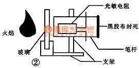
Domestic gas water heaters should be installed in well-ventilated place which is outside of the bathroom, but this, people in the bathroom can not clearly observe the combustion heater. Sometimes water heater can not ignite due to insufficient water pressure or other reasons, or being blown off after ignite, people can discover in time, only through the water temperature changes to determine the water heater. So the designer makes a simple and convenient water heater combustion detection device for people observing water heater combustion without going out.
(View)
View full Circuit Diagram | Comments | Reading(676)
The making circuit of crystal oscillator 80mW F.M. transmitter
Published:2011/7/20 0:44:00 Author:Fiona | Keyword: crystal oscillator, F.M. transmitter

Crystal oscillator 80mW F.M. transmitter's making circuit is shown as above:
(View)
View full Circuit Diagram | Comments | Reading(2035)
The water level detection circuit
Published:2011/7/12 3:58:00 Author:zj | Keyword: The water level, detection circuit
View full Circuit Diagram | Comments | Reading(887)
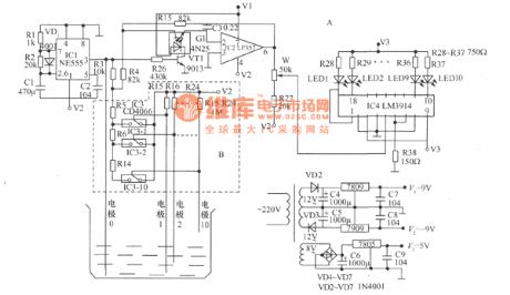
The food humidity detector circuit (1)
Published:2011/7/21 0:13:00 Author:Borg | Keyword: food humidity detector
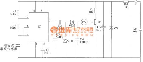
Element selectionR1~R3 are adopted with the 1/4 carbon film resistor; R4 is the 1/2W metal film resistor; RP is the mixed film potentiometer; C1 and C2 are the dacron capacitor or the monolith capacitor; C3 and C4 are the high frequency pottery capacitor; C5 is the aluminum electrolytic resistor with the withstand voltage of 16V; VD1 and VD2 are the 2AP9 ordinary Ge diodes or IN4148 silicon switch diodes; VS is the 2CW14 or 2CW55(1/4W, 6~7.5V) regulated diode. (View)
View full Circuit Diagram | Comments | Reading(689)
The temperature detection alarm circuit
Published:2011/7/20 23:57:00 Author:Borg | Keyword: alarm circuit
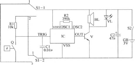
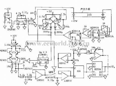
Here is to introduce the temperature detection alarm circuit, which is made of the heat temperature and audio integrated circuit, it characterizes simple and practical circuit, it can not only be used as the over-temperature alarm, but also be the low-temperature alarm.The temperature detection alarm circuit consists of the temperature detection control circuit and acousto-optical alarm circuit, see as the figure.
(View)
View full Circuit Diagram | Comments | Reading(859)
Single-chip test board circuit 5
Published:2011/7/24 22:30:00 Author:Ecco | Keyword: Single-chip , test board
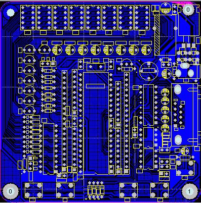
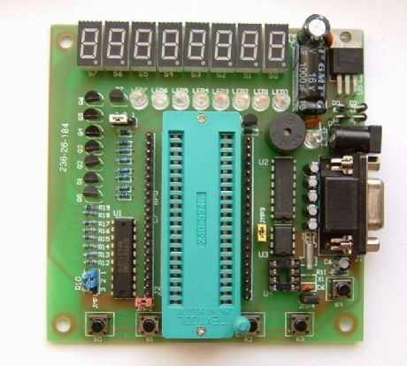
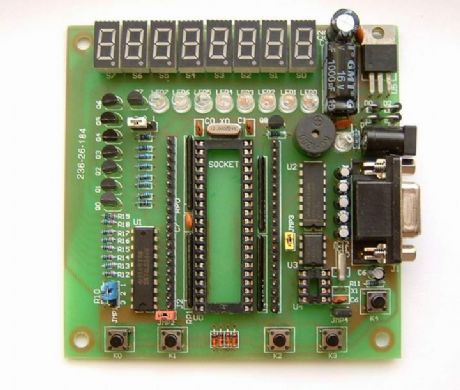
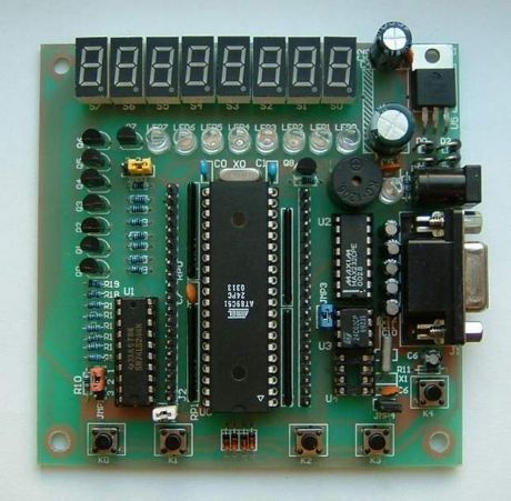
Jumper JMPO's role: it is used for the digital test unit and water light testing unit conversion, when it is short connected at the location of 12, the water light unit is effective; when it is short connected in the 23 position, the digital control unit is effective. Jumper JMP1's role: it is used to control the output enable of 74LS244 driver, when it is short connected in position 12, the enable is in the default location of the experimental board; when it is short connected at 23 position, all the output of the 74LS244 is in the low level, and it is no longer controlled by the microcontroller output. (View)
View full Circuit Diagram | Comments | Reading(1084)
Telephone disconnection detection circuit diagram
Published:2011/7/24 21:45:00 Author:Ecco | Keyword: Telephone disconnection detection, MOSFET
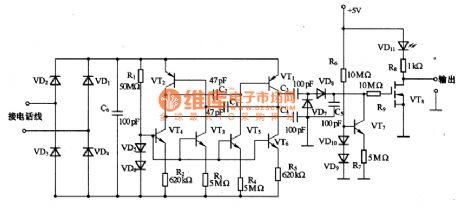
The chart shows the telephone disconnection detection circuit, which is based on the offset micro power consumption oscillator provided by telephone lines, and it generates differential signals, which is added to the circuit by the high voltage capacitor. These capacitors can provide the necessary isolation, and only when the output load of the oscillator itself is negligible, the detection circuit can detect oscillation. Oscillator uses the astable multivibrator composed of VT1 and VT2. This oscillator depends on the transistor collector resistance.
(View)
View full Circuit Diagram | Comments | Reading(779)
74 series digital circuit 74180, 74HC180 9-bit parity generator/checker
Published:2011/7/19 2:42:00 Author:TaoXi | Keyword: 74 series, digital circuit, 9-bit, parity, generator, checker
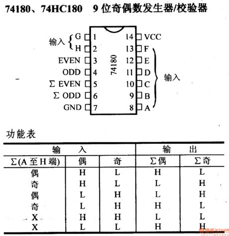
74 series digital circuit 74180, 74HC180 9-bit parity generator/checker
(View)
View full Circuit Diagram | Comments | Reading(3137)
Medical thermometer circuit
Published:2011/7/22 1:15:00 Author:Ecco | Keyword: Medical thermometer
View full Circuit Diagram | Comments | Reading(929)
Temperature Measurement Circuit One of Thermistors
Published:2011/7/11 7:45:00 Author:Michel | Keyword: Thermistors, Temperature Measurement
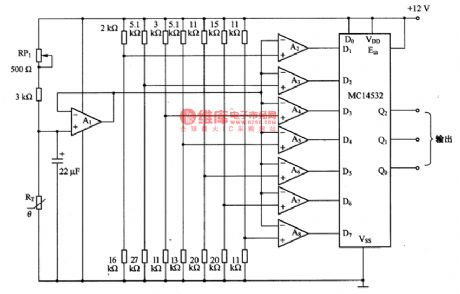
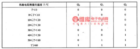
The picture is the temperature measurement circuit one of thermistors.Thermistors RT and RP1 constitute bridge road which are used to detect the different temperature. This circuit has many components but the performance is very good. Comparator A2一A8 are used to test measuring temperature range and they output 8 different temperature via MC14532 and please see the above form.
Adjusting method is as follows.30℃ 8.4 Ok Ω ordinary resistance is connected to the circuit,RP1 resistance value becomes bigger gradually from the minimum value and RP1 resistnace value is fixed and the resistance measurement precision temperature range is 土2℃ when the output code is 110一001. (View)
View full Circuit Diagram | Comments | Reading(1081)
NC Lathe detection circuit
Published:2011/5/13 3:45:00 Author:Nicole | Keyword: NC Lathe
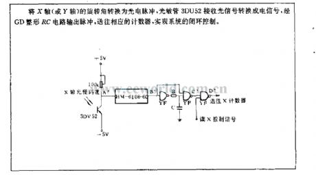
The rotation angle of X axis(or Y axis) is transformed into photoelectric pulse, photosensitive tube 3DU52 receives optical signal then change into electrical signal, RC circuit output pulse reshaped byGD , sending to the counter, to achieve the system closed loop control. (View)
View full Circuit Diagram | Comments | Reading(665)
A circuit using the reflected light of photoconductive LED to detect displacement
Published:2011/7/6 20:17:00 Author:zj | Keyword: reflected light, photoconductive LED, detect displacement
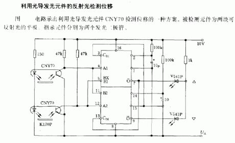
A circuit which uses the reflected light of photoconductive LED to detect displacement.The circuit diagram shows a program which uses the reflected light of photoconductive LED CNY70 to detect displacement.The detected diodes are two reflective flats.The indicating devices are two LED. (View)
View full Circuit Diagram | Comments | Reading(1370)
Bar code singal regulating circuit
Published:2011/5/13 3:04:00 Author:Nicole | Keyword: bar code, singal regulating
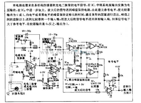
This circuit is used to handle the level singal from bar code scanner photodiode, it can change the current output into voltage output in IC1, then it is further amplified by IC2. Amplificative singal is sent to peak value hold circuit, then it will build a reference level, the comparator output is 0 or 1. The peak value of white level or black level should keep long time enough, then it will be read-out by bar code pattern. The difference between peak value is divided by 2 then transported to a output terminal of comparator; and the amplificative singal level is transported to phase reversal inout terminal. If the singal level is higher than reference level, the comparator output is 0, contrarily, the output is 1. (View)
View full Circuit Diagram | Comments | Reading(900)
Ultraweak luminescence measurement circuit
Published:2011/5/13 2:51:00 Author:Nicole | Keyword: ultraweak luminescence
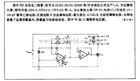
In the figure, PD is photodiode, the model are S1226, S1336, S2386(produced by Janpan Hamamatsu Corporation); A1 is operational amplifier, the model are AD515, OPA111, OPA128; A2 is operational amplifier OP-07; capacitance(C1)can use 10~100pF polystyrene capacitance; feedback resistance R is metal glaze resistance, the maximum can reach 10GΩ; K is low leakage relay. The circuit is in metallic shield box, the shield box is connected to circuit grouding. In the figure, W uses 10 rounds precise potentiometer. (View)
View full Circuit Diagram | Comments | Reading(1097)
Nanosecond pulse test circuit
Published:2011/5/12 22:25:00 Author:Nicole | Keyword: nanosecond pulse, test
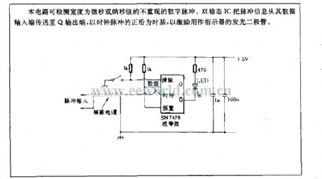
This circuit can test the digital pulse not repeated, and its width is microsecond or nanosecond. Bistable IC transmits pulse information from data input terminal to Q outout terminal, it uses the positive edge of clock pulse as time base, it is used to inspire LED which is used as indicator. (View)
View full Circuit Diagram | Comments | Reading(1051)
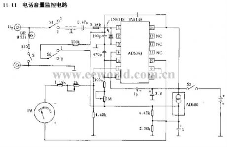
Telephone volume control circuit
Published:2011/7/20 2:34:00 Author:zj | Keyword: Telephone, volume control
View full Circuit Diagram | Comments | Reading(818)
The hardware circuit diagram of AC voltage measuring module system
Published:2011/5/12 0:35:00 Author:Nicole | Keyword: AC voltage, measuring module, hardware
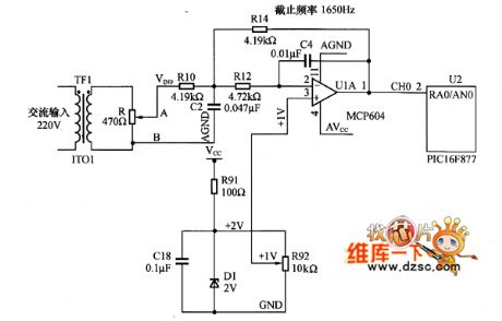
VREF's value is adjusted by potentiometer R92, the voltage is improved to 2V, after the AC input voltage with 2V amplitude is rised, it outputs 0~4V monopolar voltage. In order to ensure thatthe sample voltage can reflect the analog signal adequately, it should has enough sampling numbers in a power frequency cycle, the sampling numbers are decided by sampling theory and the considered harmonic number.
A 220V/8V transformer changes 220V network voltage into 8V AC voltage, a 470Ω partial pressure potentiometer is connected to it, then it can be adjusted to AC voltage with 2V amplitude, after improving, the circuit is transfered into a 0~4V monopolar voltage singal.
(View)
View full Circuit Diagram | Comments | Reading(2695)
Rapid zeropassage detector circuit
Published:2011/7/17 1:53:00 Author:Fiona | Keyword: zeropassage, detector
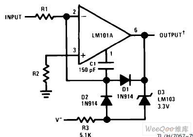
Rapid zeropassage detector circuit is shown as above:
(View)
View full Circuit Diagram | Comments | Reading(621)
| Pages:86/101 At 2081828384858687888990919293949596979899100Under 20 |
Circuit Categories
power supply circuit
Amplifier Circuit
Basic Circuit
LED and Light Circuit
Sensor Circuit
Signal Processing
Electrical Equipment Circuit
Control Circuit
Remote Control Circuit
A/D-D/A Converter Circuit
Audio Circuit
Measuring and Test Circuit
Communication Circuit
Computer-Related Circuit
555 Circuit
Automotive Circuit
Repairing Circuit