
Measuring and Test Circuit
Index 82
AUDIO_BREAKOUT_BOX
Published:2009/6/18 2:48:00 Author:May
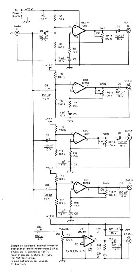
In many radio shacks, one receiver audio-output line feeds a multitude of add-ons, such as one or more TNXs, SSTV modems, PC plug-in boards, and, perhaps, speakers. Having to manually plug the audio source from one accessory to another is inconvenient, if not frustrating as well. Overload-ing the sources by connecting the loads in parallel isn't satisfactory, either.The audio breakout box takes the audio output from a receiver (or other audio source) and ap-plies it to the inputs of four identical, independent, low-level N' buffer/amplifiers and one high-level (1-W qutput) AI' channel. Each low-level output channel can provide up to 20 dB of gain that's in-dependently adjustable. (View)
View full Circuit Diagram | Comments | Reading(934)
TYPICAL_NE567_TONE_DECODER_CIRCUIT
Published:2009/6/18 2:47:00 Author:May
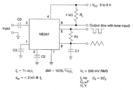
This circuit illustrates use of NE567 as a tone decoder. (View)
View full Circuit Diagram | Comments | Reading(2693)
FM_STEREO_DECODER
Published:2009/6/18 2:46:00 Author:May
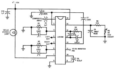
Using an LM1800, this circuit takes composite baseband MPX input and recovers L7R audio channels. The VCO is set for 19 kHz (or 15.7 kHz for TV applications) or as needed. (View)
View full Circuit Diagram | Comments | Reading(1203)
DTMF_DECODER
Published:2009/6/18 2:44:00 Author:May
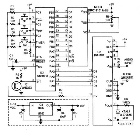
This DTMF decoder uses a Motorola 68705P3 microcontroller and a 75T202 DTMF receiver (Sil-icon Systems, Inc.). An LCD module is used for the display (MOD1). Switch S1 is used to scroll the display, S2 clears the display, and 53 clears the memory. (View)
View full Circuit Diagram | Comments | Reading(2678)
AIR_FLOW_DETECTOR
Published:2009/6/17 23:14:00 Author:May
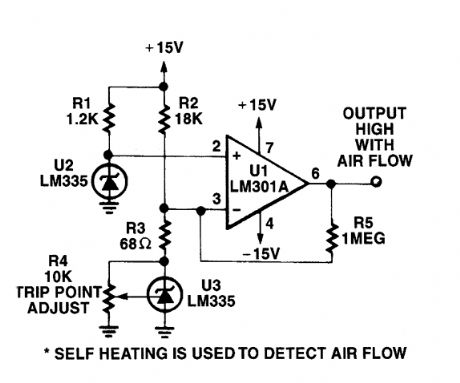
The self heating of a semiconductor that is cooled by airflow is used as a sensing method. (View)
View full Circuit Diagram | Comments | Reading(0)
ELECTRONIC_ANEMOMETER
Published:2009/6/17 23:11:00 Author:May
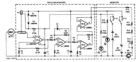
A motor used as a generator is used as a transducer to generate a dc voltage that is proportional to wind speed. K1 prevents the transducer voltages from being applied to the circuit if no dc power is present. UIA through UID is a dc amplifier, integrator, and buffer. This circuit drives the meter M1.The processor bqard is mounted in a housing along with the generator M1. (View)
View full Circuit Diagram | Comments | Reading(1576)
HOT_WIRE_ANEMOMETER
Published:2009/6/17 23:07:00 Author:May
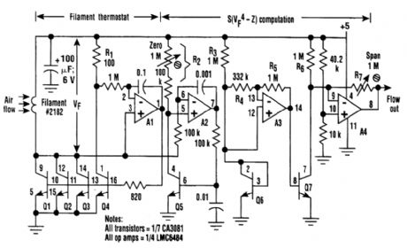
An anemometer can be realized by utilizing the inherent transconductance match of transistors in the array, instead of passive series resistances, to control filament current. As a result, as Al serves the collector current of Q4 and thereby the voltage across RI, it simultaneously adjusts the filantent (a 2182-type incandescent lamp denuded of its glass envelope) voltage, Vf. The ratio of the filament to RI current is stably maintained by the identical temperature and operating points of Q1 through Q4. The net result is that Al drives the filament temperature to the value that causes filament resis-tance to equal R1/3 = 33Ω. This is about double the cold resistance of the filament and therefore, as-suming tungsten wire with a 0.0045/degree coefficient of resistance, represents a filament operating temperature of around 230℃. This is hot enough that moderate changes in ambient temperature are unimportant factors in filament power demand, but not so hot as to cause the filament to burn.
Rail-to-rail input amplifier A2 continuously serves the collector current of Q5 to Vf/R2, making the Vbe of LQ5 a logarithmic function of Vf. A3 multiplies this log by 4 and applies the product of Q7.Q7 does the antilog function so that its collector current is proportional to the fourth power of Vf.Thus, by King's law, it's proportional to air speed in the vicinity of the filament. This current is offset and scaled by A4 to produce a voltage output that, thanks to the rail-to-rail output capability of the LMC6484, can range from 0.01 to 4.99 V Full-scale air speed can be adjusted, using R7, to any value in the range of 1 to 10 meters/s. (View)
View full Circuit Diagram | Comments | Reading(9)
LOW_COST_METAL_DETECTOR_FOR_EXPERIMENTERS
Published:2009/6/17 22:33:00 Author:May
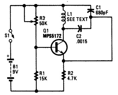
This circuit is on oscillator with L1 being a 4 diameter coil of 35 turns of #26 magnet wire.Metal in proximity to L1 will cause the oscillator to shift frequency. An AM transistor radio is used to detect the frequency shift. (View)
View full Circuit Diagram | Comments | Reading(917)
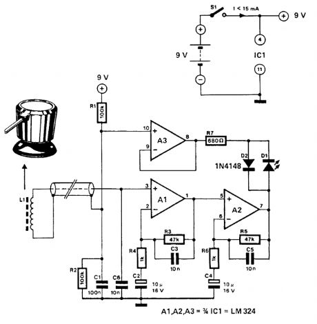
METAL_PIPE_DETECTOR
Published:2009/6/17 22:32:00 Author:May
This circuit uses a 15-kHz oscillator coil. When metal placed in the energy field is withdrawn, the oscillator voltage is rectified and compared to a reference. A drop in oscillator voltage therefore op-erates comparator IC2 and D4 (LED) extinguishes. (View)
View full Circuit Diagram | Comments | Reading(1232)
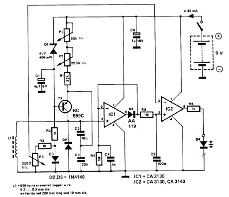
ZENER_DIODE_TEST_SET
Published:2009/6/17 22:30:00 Author:May
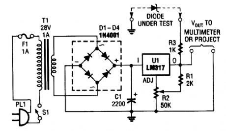
This versatile circuit can be used to test zener diodes or act as a stand-alone power supply. It re-quires a voltmeter to work as a zener tester. (View)
View full Circuit Diagram | Comments | Reading(4608)
AUDIO_FREQUENCY_METER_CIRCUIT
Published:2009/6/17 22:30:00 Author:May
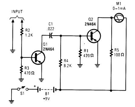
This simple tachometer circuit uses a pulse shaper Q1 to drive M1, a 0- to 1-μA meter. C1 can be varied to optimize operation. (View)
View full Circuit Diagram | Comments | Reading(886)
SUPPLY_VOLTAGE_MONITOR
Published:2009/6/17 22:29:00 Author:May
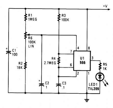
Excessive voltage causes U1 to oscillate, causing LED1 to flash. R6 sets the desired trip level. (View)
View full Circuit Diagram | Comments | Reading(672)
CONTINUITY_TESTER_FOR_LOW_RESISTANCE_CIRCUITS
Published:2009/6/17 22:28:00 Author:May
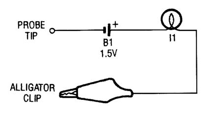
The continuity tester is little more than a battery and a lamp connected in series, with one end of the string terminated in an alligator clip, and the other end connected to the probe tip. (View)
View full Circuit Diagram | Comments | Reading(1845)
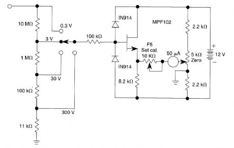
CHECK_FOR_op_AMP_dc_OFFSET_SHIFT
Published:2009/6/17 22:28:00 Author:May

The dc values of op-amp offsets can't always be taken for granted when delivering ac outputs. No device is ever exactly symmetrical for maximum positive slew rate versus maximum negative slew rate. Consequently, there is always some range of output slew rates in which the device used limits in one direction more severely than in the other. What results in rectification of the ac signal and an apparent shift of the dc offset.This test circuit can check for the shift phenomenon. The accompanying table and graph illus-trate the results obtained for four devices, all of different types. As frequency and slew rate are in-creased, the effect can be either relatively abrupt (LF412CN and NE55532N) or relatively gradual (LF358J and TL082CP). (View)
View full Circuit Diagram | Comments | Reading(1337)
JFET_VOLTMETER
Published:2009/6/17 22:26:00 Author:May
This very simple voltmeter circuit uses a 50-pA meter in a bridge circuit. It is useful for noncrit-ical applications. (View)
View full Circuit Diagram | Comments | Reading(876)
ac_OUTLET_TESTER
Published:2009/6/17 22:25:00 Author:May
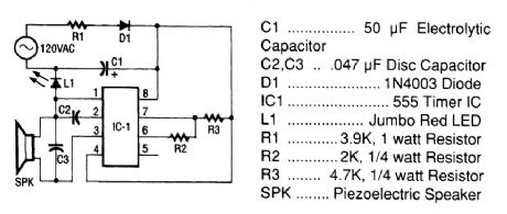
The tester consists of a rectifier circuit and a multivibrator circuit. The ac voltage is half-wave rectified by diode D1 and stored in capacitor C1. Resistor R1 is used to limit the current through D1 to a safe value. The voltage stored across C1 supplies IC1 operating powen The IC, the versatile 555 timer, is configured to operate as a multivibration whose operating frequency is determined by C2, R2, and R3. The output of IC1, on pin 3, is coupled to a piezoelectric speaker (SPK), which gives an indication of the presence of ac. An LED (L1) also lights when ac is present. (View)
View full Circuit Diagram | Comments | Reading(890)
AUDIBLE_CONTINUITY_TESTER
Published:2009/6/17 22:25:00 Author:May
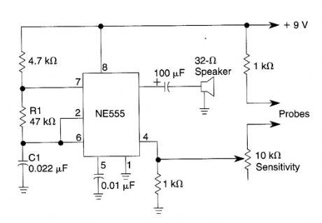
This 555 oscillator sounds a tone when continuity exists between the probes. Oscillator frequency is deterrrtined by the values of R1 and C1. (View)
View full Circuit Diagram | Comments | Reading(1)
ac_WIRING_LOCATOR
Published:2009/6/17 22:24:00 Author:May
This circuit uses a pick-up coil to sense the 50-or 60-Hz field around telephone pick-up coil with a suction pad. D1 (LED) lights during positive ac current is present. (View)
View full Circuit Diagram | Comments | Reading(1073)
DEBOUNCE_CIRCUIT
Published:2009/6/17 22:23:00 Author:May
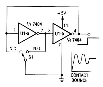
This debounce circuit will keep the electrical noise generated by the mechanical switch (S1) from reaching the next circuit in line. (View)
View full Circuit Diagram | Comments | Reading(1234)
LINEAR_INDUCTANCE_METER
Published:2009/6/17 22:22:00 Author:May
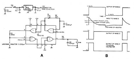
Using the fact that in an RL circuit, the pulse width seen across the inductor is proportional to the inductance, this circuit reads this indirectly on a DVM. The range is about 5 to 250 μH. (View)
View full Circuit Diagram | Comments | Reading(1035)
| Pages:82/101 At 2081828384858687888990919293949596979899100Under 20 |
Circuit Categories
power supply circuit
Amplifier Circuit
Basic Circuit
LED and Light Circuit
Sensor Circuit
Signal Processing
Electrical Equipment Circuit
Control Circuit
Remote Control Circuit
A/D-D/A Converter Circuit
Audio Circuit
Measuring and Test Circuit
Communication Circuit
Computer-Related Circuit
555 Circuit
Automotive Circuit
Repairing Circuit