
Measuring and Test Circuit
Index 87
Low drift peak detector circuit
Published:2011/7/17 1:50:00 Author:Fiona | Keyword: Low drift, detector
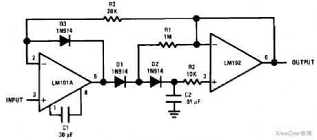
Low drift peak detector circuit is shown as above:
(View)
View full Circuit Diagram | Comments | Reading(6120)
Relative humidity measuring instrument circuit
Published:2011/7/17 8:00:00 Author:Fiona | Keyword: Relative humidity, measuring instrument
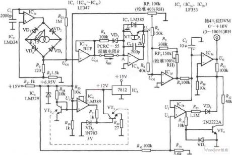
Relative humidity measuring instrument circuit is shown as above:
(View)
View full Circuit Diagram | Comments | Reading(862)
Mobile detector
Published:2011/5/13 4:27:00 Author:Ecco | Keyword: Mobile, detector

The up circuit is ultrasonic receiver and signal processing circuit, the transmitting circuit is as below. (View)
View full Circuit Diagram | Comments | Reading(1309)
The ADE7752 circuit diagram with three phase three wires system triangle connection
Published:2011/5/11 4:14:00 Author:Ecco | Keyword: three phase three wires system , triangle connection
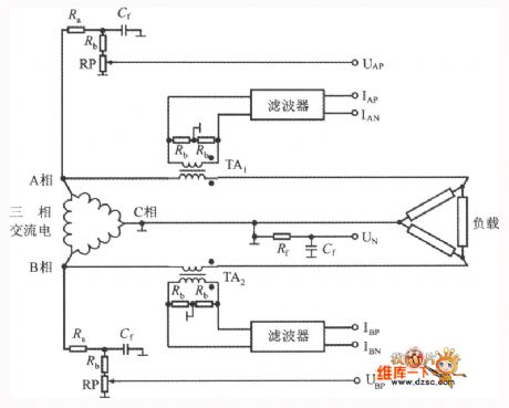
The ADE7752circuit that adopts three phase three wires system triangle connecting laws is shown as below. only in this case use the two voltage input and current input ports of ADE7752. The active power caculated by the ADE7752 has nothing to do with the gateway it chosen.as the gateway chosen. (View)
View full Circuit Diagram | Comments | Reading(831)
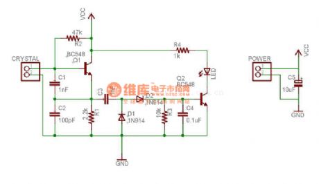
Crystal detector circuit diagram
Published:2011/5/17 4:06:00 Author:Ecco | Keyword: Crystal, detector

When buying crystals, the detector can test the quality of the high-frequency crystal. Working principle is shown as the chart, it is a Kepizi high-frequency crystal oscillator composed of VTl and sJT crystal. When itis addedsJT crystal, it can provide positive feedback loop to the base of vTl, and VT1 starts oscillation, the weak signal from oscillation will be sent to vT2 emitter by coupling capacitor c4 and drive voltage doubler detector composed of C5, C6, VDl , vD2. Then the current amplifier VT3 turns on, the light-emitting diode VD3 is lit.Among them, the emitter vT2 can provide signals to voltage doubler detector, but also IV has the effect of isolation cushion, for reaching the start-up support of VT1. When it detects crystal, sometimes the brightness of VD3 is not enough, the conclusion is not sure, you can slightly adjust the operating point R3 of transistor vT1 to achieve stable oscillation, and then adjust the gain electrical equipment RP. It needs appropriate components. Generally you do not have to adjust. Power GB uses 6F22-nc9v to cascade batteries.
(View)
View full Circuit Diagram | Comments | Reading(1070)
The unipole slab electron weighs system circuit diagram composed of ZEM series
Published:2011/5/11 4:19:00 Author:Ecco | Keyword: unipole slab , electron weighs system , ZEM series
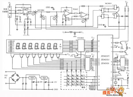
The unipole slab electronic weigh system circuit diagram composed of ZEM207 seriesis shown as below. The circuit includes the analog switch MC4066, double OPAMP TL062, a double inputs four and MC4011 in the non- portal, a seven Darlington driver UN2003(may also replace with the MC1413), a 3 wires/8 wires translator 74 HC138, a 2 Kb serial E2PROM storaging machine 24C02, three ports voltage regulations 7809, 7805. The system goes together with 7 LED displays and 4 × 4 keyboards, and display unit can select gram(g), kilo gram(kg) or ton(t). There are 8 light-emitted diode A~H, mean LW(null potential) and PZ(tare), ZL(place null) and DJ(price per unit), JE(figure ) and LC(accumulate number of times), LJ(accumulate) and LZ(accumulate weight) respectively. TXD in the chart means serial output, RXD means serial input, the BT represents low voltage indication, SW is mark of switch. U+ means connecting +9 V power supply, UCC means connecting +5 V power supply. U+L means the output voltage after returned from 9V source. (View)
View full Circuit Diagram | Comments | Reading(2681)
Intelligent pressure detection and control
Published:2011/7/12 3:02:00 Author:zj | Keyword: Intelligent, pressure detection, control
View full Circuit Diagram | Comments | Reading(691)
Voltage output angle detection circuit diagram
Published:2011/6/28 2:37:00 Author:Ecco | Keyword: Voltage, output angle, detection
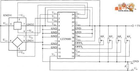
The voltage output angle detection circuit composed of the UZZ9000 and KMZ41 is shown as the chart, it uses a +5 V power supply, RP1 ~ RP2 are the offset voltage adjustment potentiometers, RP3 ~ RP4 are the gain adjustment potentiometers. The output end of R is the pull-down resistor. Output voltage can be sent to the digital voltmeter to show the measured angle values.
(View)
View full Circuit Diagram | Comments | Reading(680)
The auto reverse anti-collision ultrasonic radar circuit diagram
Published:2011/6/24 4:10:00 Author:Ecco | Keyword: auto reverse , anti-collision, ultrasonic radar
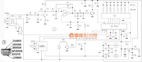
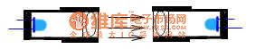
The ultrasonic radar circuit's design is reasonable,and it has been several field trials,and it works reliably. The circuit is sealed by the ultrasonic sensor R/S40 (including transmit and receive), the signal receiving and processing control circuit, alarm, display circuit and power supply etc., and the circuit is shown in photo. Each part of the circuit is described below. The ultrasonic sensor R/S40 in the circuit is not only used for transmitting ultrasound, but also receiving the reflected echo, so it has a two-way transmit / receive function.
(View)
View full Circuit Diagram | Comments | Reading(3411)
The level test circuit diagram composed of 7404 TTL hex not gate
Published:2011/5/17 4:14:00 Author:Ecco | Keyword: test circuit , TTL , hex , not gate
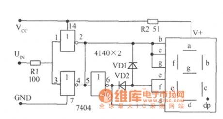
The test circuit diagram composed of 7404 TTL hex not gate is shown as the chart. The TTL (CMOS) circuit hascertain high and low level input threshold voltage, so it does not need additional setup or adjustment, the test results are very accurate. The two non-parallel gates of input side could increase driven capability, high level displays H, low level displays L. As using common anode digital tube, the polarity of VD1, VD2 changes. If it tests CMOS level, you should use a 4069 CMOS NAND gate and so on.
(View)
View full Circuit Diagram | Comments | Reading(1429)
Simple infrared alarm device installation and commissioning circuit diagram
Published:2011/6/24 3:16:00 Author:Ecco | Keyword: Simple , infrared , alarm device, installation , commissioning
The alarm device uses 7812 three-terminal fixed regulator to constitutes a regulated power supply, and it has 14V battery to ensure alarm work reliably and effectively when the AC electric supply power has failure or destroyed case. The infrared light-emitting diode VD1 uses HG504 type, and the operating current is 200mA, and radiation power is 40mW-50mW, then control distance is up to 8 meters, if the control distance is less than 5 meters, it can also use HG410 series. V1 phototransistor can use 3DU31 or 3DU5. The remaining components is chosen according to marked in the figure.
(View)
View full Circuit Diagram | Comments | Reading(549)
The capacitance test circuit composed of LM741
Published:2011/7/14 4:57:00 Author:Borg | Keyword: capacitance, test circuit
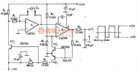
In figure 8-3 is the capacitance test circuit composed of LM741. The test principle of the circuit that the capacitor Cx under test is charging/discharging to generate a triangular wave, if the period of the wave is tested, the volume of the capacitor is known. The Miller integrating circuit can be composed of A1, and the Miller circuit composed of A2 is forming forward and backward feedbacks so the oscillation is generated, whose amplitude is decided by R4 and R3, equal to 1/3 of the power supply voltage. The charge current of Cx is decided by power supply circuit and R2, the discharging current is decided by the power supply voltage and (R1+R2). In principle, oscillating is not affected by the power supply voltage.
(View)
View full Circuit Diagram | Comments | Reading(1900)
The peak value detection circuit composed of FET
Published:2011/7/14 1:09:00 Author:Borg | Keyword: peak value, FET
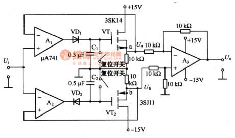
The circuit consists of the forward/negative peak value circuit and difference amplifier. A1 keeps the forward voltage at the max value, the voltage is represented at point a. A2 keeps the backward voltage at the max value, the voltage is represented at point b. A3 is the difference amplifier whose gain is 1, it can amplifier the voltage Ua at point a and Ub at spot b, by which the forward/backward peak value of the input voltage Ui can be got. The maintenance time of the circuit is decided by the grid current leakage of C1 or C2, VD1 or VD2, VT1 or VT2.
(View)
View full Circuit Diagram | Comments | Reading(775)
The manifold pressure meter circuit
Published:2011/7/11 22:38:00 Author:Borg | Keyword: manifold pressure meter
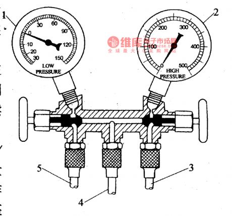
Before we add the coolant into the air-conditioner system, the air and water in it should be strained out, and the content should be controlled, or it will cause accidents. To test the vacuum degree of the air-conditioning system and the pressure after the coolant is added, we can use the manifold pressure meter and vacuum pump, etc. There is a multi-channel valve seat on the manifold pressure meter, and the low and high pressure meter on the seat, the low voltage is used to display the pressure on the low voltage side of the cooling system.
(View)
View full Circuit Diagram | Comments | Reading(923)
Electronic ballast comprehensive test instrument based on the MSP430F133
Published:2011/7/13 1:50:00 Author:TaoXi | Keyword: Electronic ballast, comprehensive, test instrument
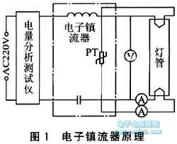
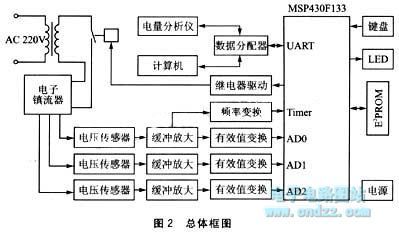
The electronic ballast principle is as shown in figure 1, the indexes that affect the electronic ballast's performance are: the preheat tube voltage of the start-up stage, the preheating filament current and preheating time, the stabilized lamp voltage, the lamp current, the oscillation frequency, the input current, the input power and the power factor, so we need to install the sensor to collector the lamp voltage of the output port, the filament current, the cathode circuit and the oscillation frequency, the power, current, power factor of the input port.etc.
(View)
View full Circuit Diagram | Comments | Reading(563)
Intelligent Single Pendulum Cycle Tester (89C2051, CD40106) Circuit Diagram
Published:2011/7/7 8:26:00 Author:Vicky | Keyword: Intelligent Single Pendulum Cycle Tester
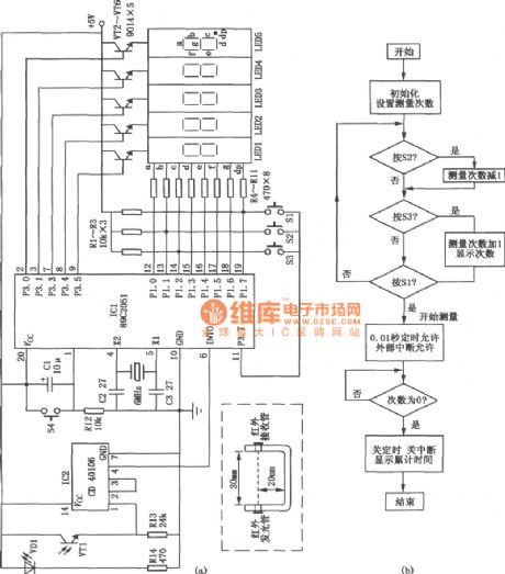
Intelligent single pendulum cycle tester circuit is shown in the picture. It is used in experiment of testing the cycle of single pendulum. The circuit is of high testing accuracy to centisecond. It can be done without human work of counting and timing. Therefore it only needs settings of the testing numbers. (View)
View full Circuit Diagram | Comments | Reading(2000)
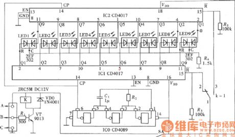
Current-Flowing-Direction Demonstrator Circuit Diagram
Published:2011/7/7 8:27:00 Author:Vicky | Keyword: Current-Flowing-Direction Demonstrator
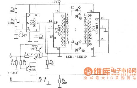
The circuit in the first picture adopts a transistor VT as input signal amplifier. VT is also used to drive a relay K. It drives the reset mode of pulse output circuit IC1& IC2’s reset end R by the changing of the relay’s contact, and thereby changes the lightening state of two-color luminous diodes to indicate the different flowing direction of the current.
The second picture is an analog demonstrating conducted by a little instrument made of CMOS digital circuit. The circuit used decimal counter/pulse distributor CD4017, together with two-color luminous diode (the colors are red and green) to constitute a analog current-flowing-direction demonstrator.
The circuit in the third picture uses work power voltage of 6V. If the work voltage needs to be changed, the resistance value of the resistance network should be re-calculated and the voltage of end R6 is 0.5V and must be lower than the voltage drop of VD2; the voltage of upper end of R5 is 0.5 and must be lower the voltage drop of VD1. (View)
View full Circuit Diagram | Comments | Reading(739)
infrared modulation demodulation circuit diagram
Published:2011/6/18 21:33:00 Author:Lena | Keyword: infrared, modulation, demodulation
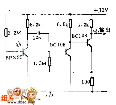
When a 1lx peak value light signal isinputted in the photoelectric cell,then the signalgo through bipolar amplifier,will output 400mV peak value;the detector sensitivity at 4KHZ is lower 3dB than at 1KHZ;when using F:2 calibration ten or parabola reflector on the infrared signal source and detector,the detect distant can be 30.48m(100 feet).This circuit can be used in high secrecy communication system.
(View)
View full Circuit Diagram | Comments | Reading(1255)
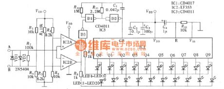
Temperature Measurement Circuit (3) of Thermistance
Published:2011/7/8 0:05:00 Author:Michel | Keyword: Thermistance, Temperature Measurement Circuit
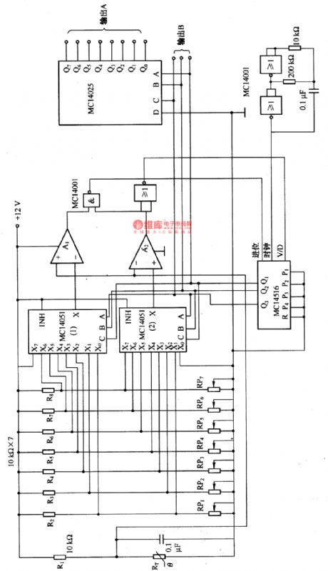
The temperature measuremnet circuit composed of thermistance etc. is shown as above. The temperature range and switch points of thermistors measurement are decided firstly.That's to say, temperature and thermistors corresponding resistance (R) are set according to the sequence of R (RPl),R2 to R(RP7), R8 (high temperature to low temperature).MC14516 is counter and the counter stop counting if the thermistance is in setting temperature range.The counting value outputs via B port and the octal signal outputs via A end. (View)
View full Circuit Diagram | Comments | Reading(1227)
Pressure test system circuit composed of the MAX1460 and the silicon pressure sensor
Published:2011/7/8 5:16:00 Author:Christina | Keyword: Pressure test system, silicon pressure sensor
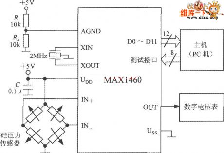
The pressure test system circuit which is composed of the MAX1460 and the silicon pressure sensor is as shown in the figure. This system uses the +5V power supply, the crystal frequency is 2MHz. The power supply voltage divider is composed of the R1 and R2, the AGND is connected at the midpoint of the power supply. The C is the power-supply decoupling capacitance. The host machine is the PC, the host machine tests the MAX1460 and receives the 12-bit parallel data which is output by the MAX1460, then it moves out the test system, the high precision intelligent pressure detection system is composed of the MAX1460 and the tested sensor, the conversion rate is 15 times/second, the measurement error is less than ±0.1%.
(View)
View full Circuit Diagram | Comments | Reading(622)
| Pages:87/101 At 2081828384858687888990919293949596979899100Under 20 |
Circuit Categories
power supply circuit
Amplifier Circuit
Basic Circuit
LED and Light Circuit
Sensor Circuit
Signal Processing
Electrical Equipment Circuit
Control Circuit
Remote Control Circuit
A/D-D/A Converter Circuit
Audio Circuit
Measuring and Test Circuit
Communication Circuit
Computer-Related Circuit
555 Circuit
Automotive Circuit
Repairing Circuit