
Measuring and Test Circuit
Index 95
Digital Photoelectric Counter Circuit Diagram
Published:2011/6/9 3:52:00 Author:Vicky | Keyword: Digital Photoelectric Counter,
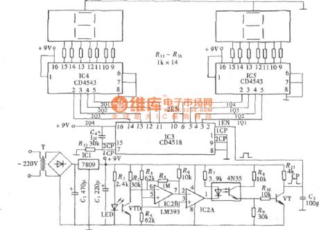
Some digital electronic counters adopt mechanical trigger, and some adopt non-contact trigger of electronic sensor; photoelectric sensor, belonging to the latter, is a non-contact electronic sensor. Photoelectric electronic counter made of photoelectric sensor is shown in the following picture. When used to counting the products in producing streamlines in the factory, this kind of counter has irreplaceable strong point. In this case, the photoelectric triggering electronic counter has only two digits, but it can expand to four digits and even more via cascading. (View)
View full Circuit Diagram | Comments | Reading(1577)
Comparative Capacitance Gradienter Circuit Diagram
Published:2011/6/9 3:58:00 Author:Vicky | Keyword: Comparative Capacitance Gradienter,
Comparative Capacitance Gradienter is used to make comparison between the tested capacitance and standard capacitance and test whether the capacity of the tested capacitance is more or less than the standard value. Comparative Capacitance Gradienter can be used to test whether some product meets the design standard or not quickly, so as to make sure that the quality of products meets the requirement. The circuit composition is as shown in the picture. (View)
View full Circuit Diagram | Comments | Reading(997)
Frequency Calibrator Circuit Diagram
Published:2011/6/9 3:59:00 Author:Vicky | Keyword: Frequency Calibrator,
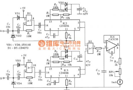
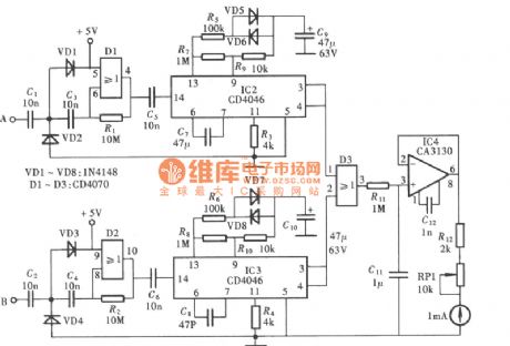
A Frequency Calibrator can be made by utilizing frequency lock, feature of PLL (Phase Locking Loop), whose circuit composition isas shown in thepicture. The circuit of Frequency Calibrator is composed of the amplifier and shaping circuit of input signal, generator circuit of standard frequency signal, comparative detection circuit of frequency signal, and indication circuit of test results. (View)
View full Circuit Diagram | Comments | Reading(1147)
Temperature-Frequency Conversion Circuit Diagram
Published:2011/6/9 3:58:00 Author:Vicky | Keyword: Temperature-Frequency Conversion Circuit, CD4046

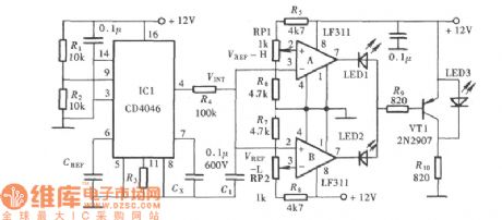
Temperature-Frequency Conversion Circuit is an indispensable part of radio telemetry temperature circuit. The principle of Temperature-Frequency Conversion Circuit is to convert the change of temperature to the change of voltage and use changing voltage to control the change of the oscillating frequency of oscillatory circuit. The changing frequency then is sent by wireless after signal encoding. After the sent signal is received by receiving set, the changing frequency would restore as value of temperature and display via the screen after demodulating, converting and decoding. The diagram of Temperature-Frequency Conversion Circuit composed of CD4046 is as shown in the picture. (View)
View full Circuit Diagram | Comments | Reading(770)
Pulse Demodulator Circuit Diagram
Published:2011/6/9 3:58:00 Author:Vicky | Keyword: Pulse Demodulator, CD4069
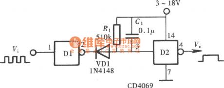
As is shown in the picture, the Pulse Demodulator is composed by CMOS Hex Inverter. This circuit can be used to process envelop detection on Amplitude Pulse. (View)
View full Circuit Diagram | Comments | Reading(1661)
The radiation tester circuit
Published:2011/6/6 2:02:00 Author:Seven | Keyword: radiation tester
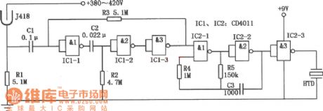
In the figure is the radiation tester circuit,which consists of the radiation testing sensor and the NAND integrated circuit CD4011. It can be used to detect the α,γ,βand X rays, and the sensitivity is high. When a few radioactive rays are detected, the tester will make intermittent noises; and when the dose of the rays is big, it will make continuous warning noises.
(View)
View full Circuit Diagram | Comments | Reading(764)
The illuminance tester circuit
Published:2011/6/6 1:32:00 Author:Seven | Keyword: illuminance tester
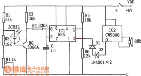
In the figure is an illuminance tester circuit. The tester consists of the photoelectric sensor, single steady trigger, stereo circuit, etc, of which the photoelectric sensor is powered by battery 2CR33.
(View)
View full Circuit Diagram | Comments | Reading(668)
Electronic Gradienter Circuit Diagram
Published:2011/6/9 3:57:00 Author:Vicky | Keyword: Electronic Gradienter,
Ordinary gradienter confirms whether the plane of tested object reached the level by observing whether the air bubble in the middle of spirit level is in the centre. Under the dim environment, naked eyes cannot see object clearly and thus is hard to justify accurately. Electronic gradienter indicates whether the plane of object reaches the level by acoustooptical change. Therefore it can be used to measure under environment of any luminance, which is very convenient. Thepicture is the circuit diagram of electronic gradienter. (View)
View full Circuit Diagram | Comments | Reading(759)
The digital capacitor tester
Published:2011/6/6 1:26:00 Author:Seven | Keyword: capacitor tester
In the figure is the digital capacitor tester. The tester consists of the time-based pulse generator, single steady trigger, addition counter, decoder, driver and LED digital pipe, etc.
(View)
View full Circuit Diagram | Comments | Reading(1065)
The controllable silicon fast tester circuit
Published:2011/6/6 1:20:00 Author:Seven | Keyword: controllable silicon, fast tester
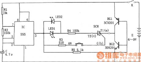
In the figure is the controllable silicon fast tester circuit. The tester consists of pulse signal generator, close-loop conducting circuit, LED and controllable silicon SCR, etc.
The pulse signal generator is a multi-resonate oscillator which consists of the time-based circuit 555, R1, R2 and C, etc, the oscillating frequency is f=1.44/(R1+2R2)C. The oscillating frequency of the parameter in the figure is about 1Hz. As R1<<R2, so the charging time of C is t(charging)=0.693(R1+R2)C, and it is close to the discharging time which is 0.693R2C, so the duty cycle of the output pulse is close to 1:1. (View)
View full Circuit Diagram | Comments | Reading(898)
The multi-function electric point detector and therapeutic apparatus circuit
Published:2011/6/6 1:53:00 Author:Seven | Keyword: point detector, therapeutic apparatus
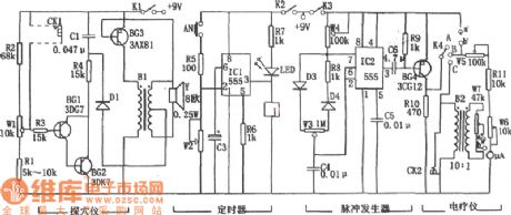
In the figure are the multi-function electric point detector and therapeutic apparatus circuit. The point detector and therapeutic apparatus consists of the point detecting circuit, timer, pulse generator and power amplifier output, etc. The point detecting circuit, which consists of BG1,BG2,R1~R4,W1,C1,BG3,B1 and so on, is factually an audio oscillator. If we insert two probes of two poles in the hole of CK1, then because the resistance of the point is low, or due to the low resistance that is caused by the ear illness, the frequency of the oscillator turns high; the longer the distance between the point and the probe is, the lower the frequency will be, so the point detection can be fulfilled. (View)
View full Circuit Diagram | Comments | Reading(570)
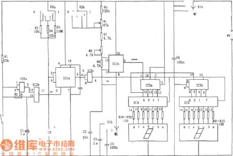
The broad range digital capacitance measuring instrument circuit
Published:2011/6/5 22:18:00 Author:Seven | Keyword: broad range, capacitance, measuring instrument
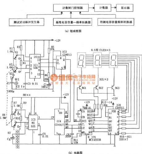
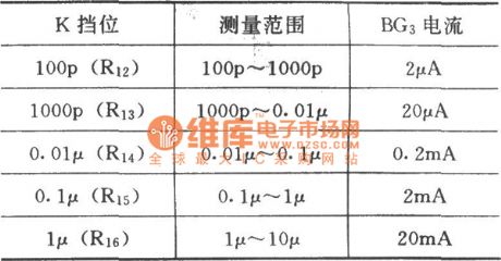
Pulse generator is a multi-resonate oscillator which consists of IC1(556), R1, R2, C1,R3, R4, C2 and so on, the oscillating frequency is f1= 1.44/(R1+2R2)C1, or f2=1.44/(R3+2R4)C2。The output pulse of 9-pin rises and the output terminal Q of D trigger IC2(CD4013) generates a low LEV, and the low LEV is added to the EN terminal of the counter IC4(cd4017), which makes the counter in the working state. The pulse output by the 5-pin controls the DIS pole of the 3 bit BCD counting circuit IC5(MC14553B). The capacitor volume under test --frequency shift circuit consists of R7,R8,IC3 and the capacitor Cx under test.
(View)
View full Circuit Diagram | Comments | Reading(727)
The simple coil turn number measuring instrument circuit
Published:2011/6/5 23:47:00 Author:Seven | Keyword: coil turn number, measuring instrument
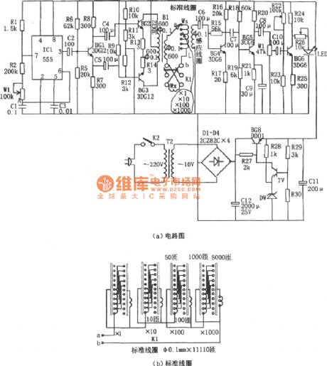
The measuring of the coil is used with magnet voltage comparing principle , i.e the coil Wx under test and the standard coil Ws are got through with a AC current I, if the two coils are connected in reversed-phase series, the total magnetomotive of them is Vm=(Ws-Wx)i. If Ws=Wx, then Vm=0, so the turn number of coil under test can be calculated by that of the standard coil. The pulse signal generator is a multi-resonate oscillator which consists of IC(555), R1, R2, W1 and CI, and its oscillating frequency is f=1.44/(R1+2R2+2Rw1)C1, the frequency of the parameter in the figure is 40~70Hz. Adjust the potentiometer W1 and make the oscillating frequency at 50z.
(View)
View full Circuit Diagram | Comments | Reading(785)
The circuit of transistor characteristic curve depicting instrument
Published:2011/6/5 22:04:00 Author:Seven | Keyword: transistor characteristic curve, depicting instrument
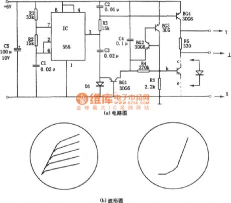
See as figure (a), the circuit consists of a sawtooth wave generator and a step wave generator. As depicting transistor characteristics needs two voltages, one the them is the step wave on b pole, by which a basic pole current is generated; the other is the sawtooth wave on C pole. The period is corresponding to the step wave, so that the output characteristic curve of the transistor can be depicted, i.e the characteristic curve of Ic-Vce. The sawtooth wave generator consists of the multi-resonate oscillator (IC(555),R1,R2 and C1) and the integration circuit(C2 and R3).
(View)
View full Circuit Diagram | Comments | Reading(801)
The crystal test circuit
Published:2011/6/5 21:51:00 Author:Seven | Keyword: crystal test
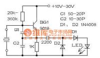
With some simple elements, we can make a crystal test circuit which can detect the frequency ranges 10kHz-100MHz, BG1 connects with a multi-resonate oscillator, after being detected by C3,D1 and D2, a voltage of upper-negative and lower-positive is got on the LED, which drives the LED to flow. If the crystal is broken, the LED won't glow. This circuit can be installed in a repairing power supply, leaving 2 holes for crystal detecting elements. Notes for assembling: the two wires led out from the crystal can be too close, or the amplitude will be highly reduced and the LED won't flow.
(View)
View full Circuit Diagram | Comments | Reading(785)
The intelligent voltmeter circuit
Published:2011/6/5 21:31:00 Author:Seven | Keyword: digital voltmeter
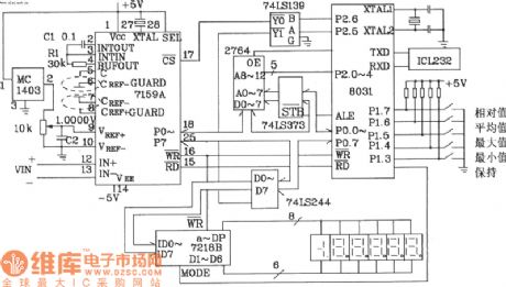
View full Circuit Diagram | Comments | Reading(638)
The diode fast selector circuit
Published:2011/6/6 22:13:00 Author:qqtang | Keyword: fast selector
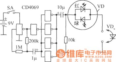
Before the test on diode parameter, we should complete the selection on the readiness of the diode, so that we can delete the useless diodes. At the moment, it time-consuming to do test with multimeter or transistor curve tracer, because both a forward and backward test should be done, and the polarity of the dim pipes should be told. With the circuit in the figure, the polarity needn't be noticed, just insert it into the hole and we can make judgement.
(View)
View full Circuit Diagram | Comments | Reading(703)
The survey meter circuit of LED display
Published:2011/6/6 21:38:00 Author:qqtang | Keyword: survey meter, LED display
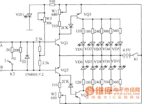
In the figure is the survey meter circuit of LED display, which can play a big part in solving some physical experiment problems. A and B are the input terminals of the current under test. Transistors of VQ1, VQ3 and VQ2, VQ4 form the coupling DC amplifier of common emitting poles on the two sides, respectively, and the LED of VD1~VD5 and VD6~VD10 are the display elements of two directions. When the current flows to B from A, the transistor of VQ2 cuts down its basic pole LEV, the working voltage is going down and VQ4 is blocked with it. (View)
View full Circuit Diagram | Comments | Reading(1197)
The temperature measuring circuit
Published:2011/6/6 21:51:00 Author:qqtang | Keyword: temperature measuring
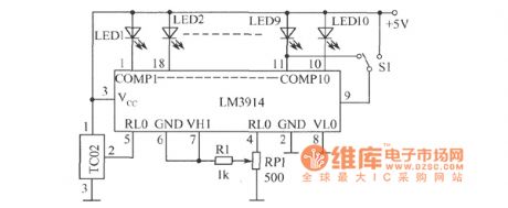
In the figure is the temperature measuring circuit, and S1 is the point/bar display mode shifting switch. When the voltage of the power supply is Vcc>8V, LED1~LED10 don't need to connect the current limiting resistor in the serial way. When LED is glowing, the current is set by the external resistors of 4-pin and 6-pin, if 4-pin and 6-pin connect a resistor of 1.2kΩ(including the resistors btween R1, BP1 central head and 4-pin), which connects with transformer of 10kΩ in LM3914 in the parallel way, and then the resistance between 4-pin and 6-pin is about 10.7kΩ, the basic voltage of 1.25v provides the transformer circuit with a current of 1.25V/1.07kΩ≈1.2mA. (View)
View full Circuit Diagram | Comments | Reading(627)
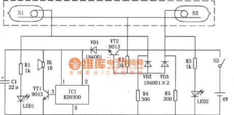
Access room people number counter circuit
Published:2011/6/8 3:04:00 Author:Christina | Keyword: Access room, people number, counter
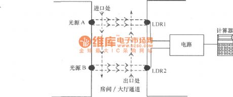

Working principle: Two pairs of photoelectric detection devices are installed in the access channel. On one side the light source A (transmitter) and the photoresistor LDR1 (receiver) are installed in the entrance of the channel; on the other side, the light source B (transmitter) and the photoresistor LDR2 (receiver) are installed in the outlet of the channel. The two beams of light need to illuminate on the receiver's photoconductive resistance, and the light beams require the precise orientation. The light source and the receiver's installation location is as shown in the figure.
Components selection: The IC1 uses the 7809, 9V regulator ; the IC2 uses the CD4093 four-two input trigger, the IC3 uses the four-two input AND gate. (View)
View full Circuit Diagram | Comments | Reading(2460)
| Pages:95/101 At 2081828384858687888990919293949596979899100Under 20 |
Circuit Categories
power supply circuit
Amplifier Circuit
Basic Circuit
LED and Light Circuit
Sensor Circuit
Signal Processing
Electrical Equipment Circuit
Control Circuit
Remote Control Circuit
A/D-D/A Converter Circuit
Audio Circuit
Measuring and Test Circuit
Communication Circuit
Computer-Related Circuit
555 Circuit
Automotive Circuit
Repairing Circuit