
Measuring and Test Circuit
Index 93
The RX3310A reception module circuit
Published:2011/6/16 22:14:00 Author:qqtang | Keyword: reception module circuit
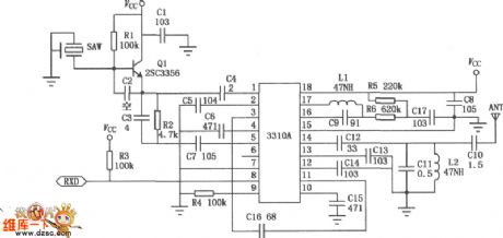
The RX3310A module is a wireless remote control and digit transiting signal reception module which is specially used in amplitude key control ASK modulation. This module is made of high function wireless remote control and digit transiting special integrated circuit, which contains the low-noise high-frequency amplifier, mixer, local oscillator, intermediate frequency amplifier, intermediate frequency filter, comparator and so on, and it is also fixed with the 316.8MHz sound surface wave resonator, so that it works stably and it's fitted to work in bad conditions.The superhet receiving module circuit of RX3310A:
(View)
View full Circuit Diagram | Comments | Reading(1983)
The manufacture/process locating principle circuit
Published:2011/6/11 22:00:00 Author:qqtang | Keyword: manufacture/process locating, principle circuit
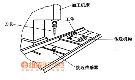
The manufacture/process locating principle circuitmanufacture/process locatingOn the auto line of the mechanical process, we can also use the approaching sensor to locate the processed components. In the figure is the process locating principle circuit. When the conveyor sector takes the processed parts close to the sensor, the sensor will send the control signals according to the regulation and make the conveyor sector stop working, at the moment, the processing tools can work on the parts.
Figure: the manufacture/process locating principle circuit (View)
View full Circuit Diagram | Comments | Reading(621)
The mechanical arm movement spacing principle circuit
Published:2011/6/11 21:49:00 Author:qqtang | Keyword: mechanical arm, movement spacing
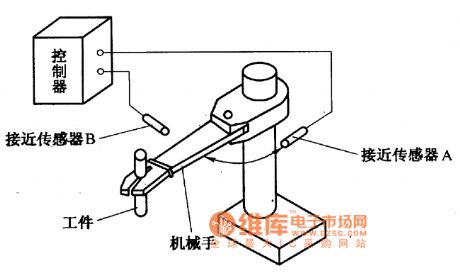
To make sure the mechanical catches and put workpieces in the right place, we often use the approaching sensor to limit its moving range. In the figure is the control diagram of the mechanical left/right movement spacing. The sensor is located in the place where the mechanical arm needs spacing, when the mechanical are moves left/right and gets close to the sensor, the sensor will output the control signal if it detects that the mechanical arm is approaching and reaches the regulated range, and the mechanical arm is stopped by the executing sector.
Figure:The mechanical arm movement spacing principle circuit (View)
View full Circuit Diagram | Comments | Reading(648)
The absolute value detection circuit
Published:2011/6/15 2:43:00 Author:Borg | Keyword: absolute value, detection
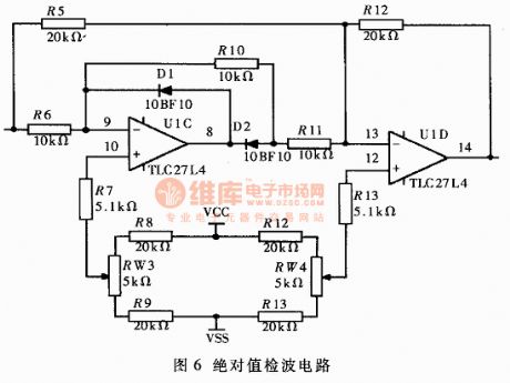
By the absolute value detection circuit (see as figure 6), we can settle the absolute values of the communication signals, which is convenient for the indication of the acceleration value. when the input signal Vin>0, the output signal Vout=Vin; but when Vin<0, Vout=-Vin.
Figure 6. The absolute value detection circuit (View)
View full Circuit Diagram | Comments | Reading(1068)
infrared modulation detection circuit diagram
Published:2011/5/11 1:46:00 Author: | Keyword: infrared, modulation, detection
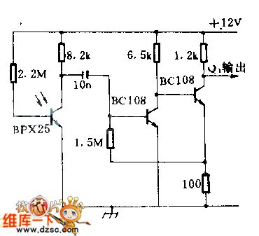
When a 1lx peak value light signal isinputted in the photoelectric cell,then the signalgo through bipolar amplifier,will output 400mV peak value;the detector sensitivity at 4KHZ is lower 3dB than at 1KHZ;when using F:2 calibration ten or parabola reflector on the infrared signal source and detector,the detect distant can be 30.48m(100 feet).This circuit can be used in high secrecy communication system.
(View)
View full Circuit Diagram | Comments | Reading(765)
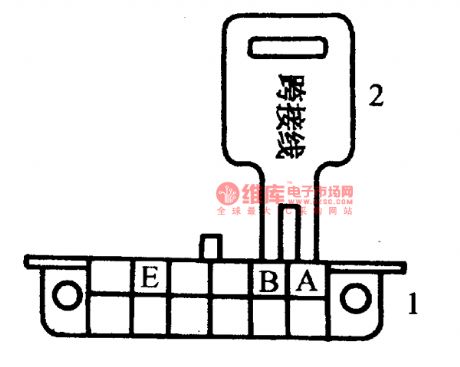
The flash sequence of the Daewoo fault code of 12
Published:2011/5/19 21:46:00 Author:Borg | Keyword: flash sequence, Daewoo
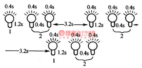
Flashing code reading: if the igniting switch is on but the engine is not running, connect the diagnosis plug with the ground, then the code can be got by flashing the fast repairing motor indicator. The character of the flashing sequence are: SES is on for 0.4s,SES is off,SES is off for 0.4s; the digital interval is 1.2s; code interval is 3.2s. The the flashing sequence of the normal code of 12 is seen in Figure 10.
The sequence of fault codes:The 10 bit number flash whose interval is 0.4sBreak for 1.2sThe 1 bit number whose interval is 0.4s.
(View)
View full Circuit Diagram | Comments | Reading(733)
The fault self-diagnosis circuit of Tianjin Xiali TJ710OE
Published:2011/5/26 22:03:00 Author:Borg | Keyword: fault self-diagnosis circuit, Tianjin Xiali
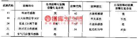
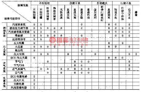
There is a self-diagnosis and self-protection measure in Xiali EFI system, and there is a fault diagnosis alarm lamp on the combination instrument, when the car is starting,the lamp will light, if the system is normal, the lamp will be off when the car has been started. If the e-control system sensor and igniting signal are malfunctioning, the fault alarm lamp light, however, it won't light when the CO content adjuster switch system and starting signal are malfunctioning.
(View)
View full Circuit Diagram | Comments | Reading(605)
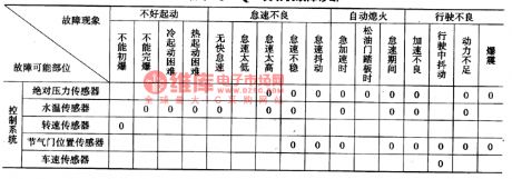
The diagnosis and repairing circuit of common fault of Daewoo-ESPERO
Published:2011/5/19 21:28:00 Author:Borg | Keyword: common fault, Daewoo-ESPERO
1.Introduction It should be in accordance with circuits when doing tests on oil injection control system, and on the basis of exact observation and practice, only after further analysis and integration can we find reliable methods. If the fast repairing motor indicator is on all the time, before we get down to solving the problem, we should ask the driver about the cause. If the engine rotates but not runs, we can solve the problem by the fault judging course in the following descripiton.
(View)
View full Circuit Diagram | Comments | Reading(662)
The micro-resistance test circuit
Published:2011/5/26 22:17:00 Author:Borg | Keyword: micro-resistance, test circuit
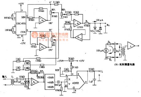
Micro-resistance is tested in the method of 4-terminal measure, i.e the tested resistance Rx is imposed with a AC stable current with the frequency of 1KHZ, the stable current only flow through Rx and it's irrelevant to the cables and touching resistance. Then the voltage between the two terminals of Rx reduces by Ui, which is tested by the sensor so that we know the resistance. The figure (a) is a actual test circuit. OSC-O5X is the 2-phase oscillator of 1KHZX, i.e a oscillator whose phase difference is 90°. The output signal is magnified by A1 and A2, then they are sent out in 4 phases of 0°,90°,180°and 270°.
(View)
View full Circuit Diagram | Comments | Reading(805)
The LEV evaluation circuit of μA741
Published:2011/5/26 23:10:00 Author:Borg | Keyword: LEV, evaluation circuit
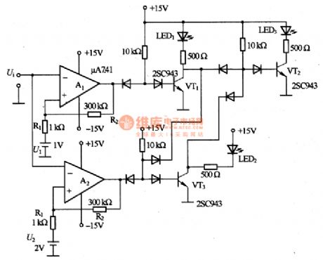
This is a LEV evaluation circuit of μA741. When the input signal Ui is lower than IV, the LED1 is glowing; when the signal ranges 1~2V, the LED2 is glowing; when the signal is higher than 2V, the LED3 is glowing. As the circuitis installed with a calculating amplifier, so we can briefly evaluate the LED of weak signals. The reference voltage of U1 and U2 is provided by a voltage-steady diode. The EH of non-sensitive area is computed in the following way, i.eIn the formula, HOU and UOL are the maximum positive and negative voltages respectively of the computing amplifiers of A1 and A2.
(View)
View full Circuit Diagram | Comments | Reading(978)
The rotating speed test circuit formed by NE555 and so on
Published:2011/5/26 23:18:00 Author:Borg | Keyword: rotating speed, test circuit
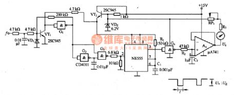
The input frequecy is a responding signal to rotating speed. The signal is shaped by the Schmidt trigger circuit which is formed by VT1 and G1, and then is differentiated by G2 and G3, then the pulse signal triggers the signle-stable multivibrator which consists of NE555. The 3-lead output comes across G4, and then runs through R2 and C2 to be integrated, finally comes across A1 buffer and comes out from the drive meter. At the same time, the output pulse width of G4 is t, amplitude is Ue, frequency is (equal to the frequency of input signals), and the output voltage of A1 is U.
(View)
View full Circuit Diagram | Comments | Reading(819)
The on-line tester circuit of diodes and triodes
Published:2011/6/10 1:36:00 Author:Seven | Keyword: on-line tester, diodes and triodes
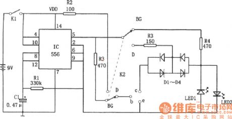
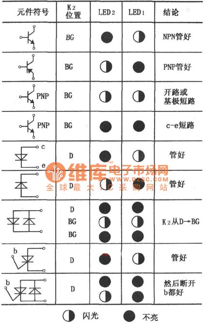
In the circuit is the on-line tester circuit of diodes and triodes. The tester consists of the multi-resonate oscillator and single steady trigger centralized on the dual time-based 556 circuit, LED1 and LED2, etc.The multi-resonate oscillator consists of half of 556, R1 and C1, etc, whose oscillating frequency is f=1.44/R1C1. The single steady trigger consists of the other half of 556, by which the output poles of 5-pin and 9-pin output a couple alternating square wave testing signals, and the couple of signals have opposite polarities and the peak voltage is 9v, the frequency is 5Hz.
(View)
View full Circuit Diagram | Comments | Reading(705)
The LEV tester circuit of voltage comparator LM324
Published:2011/6/10 0:58:00 Author:qqtang | Keyword: tester circuit, voltage comparator
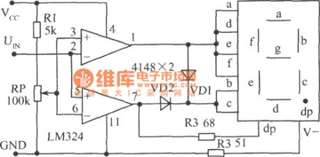
In the figure is the LEV tester circuit of voltage comparator LM324, whose character is that it's convenient for the threshold value LEV adjustment, and it can test the logic LEV of DTL, TTL, CMOS and so on. Judging from the voltage comparator, we know when the input(positive) pole voltage is higher than that of the opposite(negative) pole, the comparator outputs a high LEV, and vice versa. RP is a comparing voltage adjusting potentiometer, when UIN is higher than the set voltage, 7-pin outputs a high LEV, and it indicates 1 , the decimal dp is glowing simultaneously. (View)
View full Circuit Diagram | Comments | Reading(2510)
The LT current sensor wiring circuit
Published:2011/6/10 21:59:00 Author:qqtang | Keyword: current sensor, wiring circuit
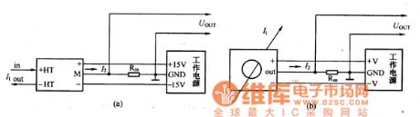
Figure:The LT current sensor wiring circuit (View)
View full Circuit Diagram | Comments | Reading(557)
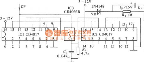
Binary-Decimal Counter Circuit Diagram
Published:2011/6/9 3:56:00 Author:Vicky | Keyword: Binary-Decimal Counter, CD4066, CD4013, CD4017
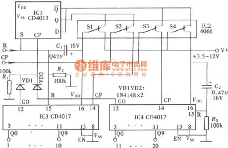
(View)
View full Circuit Diagram | Comments | Reading(1034)
The LT current sensor outline circuit
Published:2011/6/10 22:01:00 Author:qqtang | Keyword: current sensor, outline
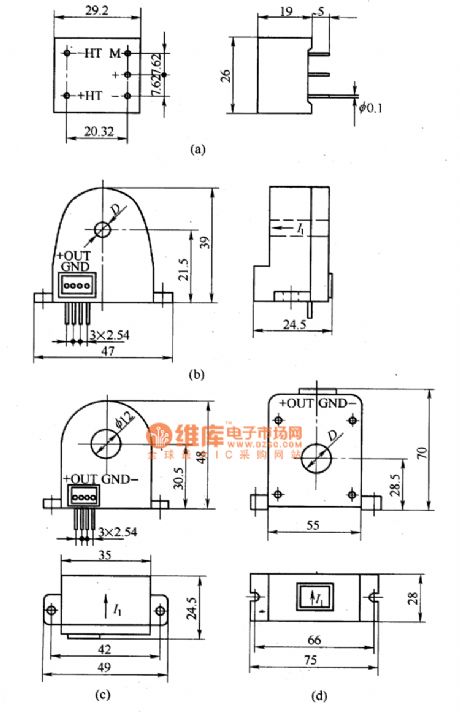
figure:The LT current sensor outline circuit (View)
View full Circuit Diagram | Comments | Reading(700)
The working principle circuit of magnetic compensatory current sensors
Published:2011/6/10 22:12:00 Author:qqtang | Keyword: working principle, magnetic compensatory current
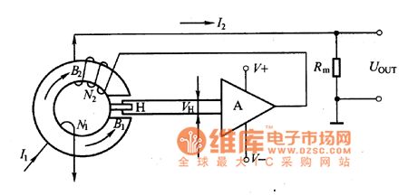
The introduction of the working principleIn the figure is the working principle circuit of magnetic compensatory current sensors. Accroding to the Ampere's law, the current under test will generate a field B2, and the field is compensated by the field generated by I2M2 and kept balanced, i.e I1M1=I2M2, so I2=I1M1/N2. When N1/N2 spot is determined, I2 is proportional to I1, and it is switched into a voltage signal by Rm and output. The Hall elements is testing the zero flux all the time.
Figure:The the working principle circuit of magnetic compensatory current sensors (View)
View full Circuit Diagram | Comments | Reading(1040)
Watt-hour meter LCD driving control integrated circuit SM9913 typical application circuit
Published:2011/5/19 19:12:00 Author:Christina | Keyword: Watt-hour meter, LCD, driving control, integrated circuit, typical application circuit
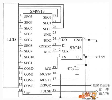
The watt-hour meter LCD driving control integrated circuit SM9913 typical application circuit is as shown. The E2PROM uses the 93C46 type 64×16b electrical erase programmable memory. The SM9913's ERROR output port can be used to test or read the data error and the internal data processing error of E2PROM, it outputs the low level voltage. It will outputs the high level voltage in following circumstances:1.Writing E2PROM data error or reading E2PROM data error; 2.Working process display data writing internal registers error; 3.Internal trigger is not working properly.
(View)
View full Circuit Diagram | Comments | Reading(1984)
Winding Machine Electronic Counter Circuit Diagram
Published:2011/6/9 3:50:00 Author:Vicky | Keyword: Winding Machine Electronic Counter,
Winding machine is one of the most commonly used tools in electrical industry. Traditional winding machine usually adopts mechanical counter. Therefore due to the wear caused by mechanical drive, the accuracy of counting cannot be guaranteed. When using the photoelectric sensor as the trigger flip-flop, due to the non-contact and high sensitivity, the accuracy of winding is high improved. This counter also has the function of addition and subtraction, and owns the unique advantage of being more convenient and accurate for error-correcting. The circuit composition diagram is as shownin the picture. (View)
View full Circuit Diagram | Comments | Reading(1843)
Electronic Sphygmograph Circuit Diagram
Published:2011/6/9 4:10:00 Author:Vicky | Keyword: Electronic Sphygmograph,
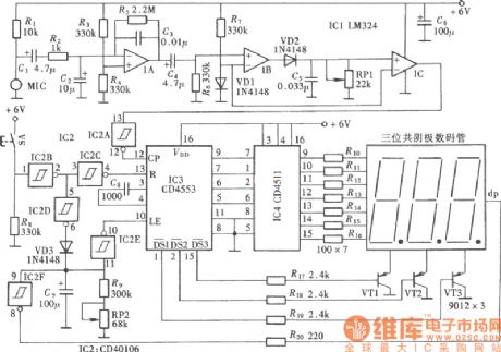
Sphygmograph and cardiotachometer are in fact two different sayings of one tester, and the difference of the two lies in the different sampling position. Cardiotachometer takes sample from breast, while sphygmograph from wrist. The following that we are going to introduce is electronic sphgmograph, and the circuit composition is as shown in the picture. (View)
View full Circuit Diagram | Comments | Reading(1247)
| Pages:93/101 At 2081828384858687888990919293949596979899100Under 20 |
Circuit Categories
power supply circuit
Amplifier Circuit
Basic Circuit
LED and Light Circuit
Sensor Circuit
Signal Processing
Electrical Equipment Circuit
Control Circuit
Remote Control Circuit
A/D-D/A Converter Circuit
Audio Circuit
Measuring and Test Circuit
Communication Circuit
Computer-Related Circuit
555 Circuit
Automotive Circuit
Repairing Circuit