
Measuring and Test Circuit
Index 91
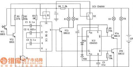
Circuit Diagram of Power Frequency Detector composed of CD4013
Published:2011/6/21 6:09:00 Author:Vicky | Keyword: Power Frequency Detector
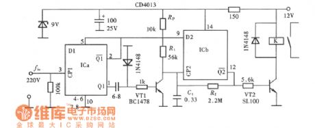
As so some electronic devices and electric apparatus, the frequency of AC power should meet a certain requirement. When the power supply is higher or lower than 50 Hz, the devices’/apparatus’ performance would be influenced, and even destroyed. Therefore, power frequency detector should be assembled for those devices/apparatus. When the power supply is not within required range of variation, the detector will give out warning or cut off the power supply automatically to ensure the security of the devices/apparatus. The above picture is power frequency detector composed of CD4013, which will cut off the working power when the power frequency is beyond a certain range around 50Hz to ensure the security of devices/apparatus. (View)
View full Circuit Diagram | Comments | Reading(2285)
AN5421 line same-frequency signal detection integrated circuit
Published:2011/6/29 3:06:00 Author:Christina | Keyword: line, same-frequency signal, detection, integrated circuit
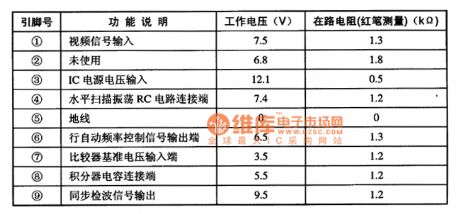
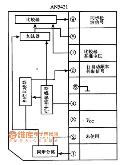
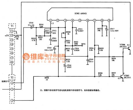
The AN5421 line same-frequency signal detection integrated circuit is produced by the Panasonic company that can be used in the Panasonic series large screen color TVs.
1.Features
The AN5421 can be used to detect the line synchronous signal from the frequency signal, and it outputs the detection result in the form of DC voltage to control the station search program of the system control microcomputer.
2.Pin functions and data
The AN5421 uses the single row 9-pin package, the pin functions and data are as shown in table 1.
Table 1 The pin functions and data of the AN5421
3. The internal circuit block diagram and the typical application circuit
The internal circuit block diagram of the AN5421 is as shown in figure 1, the typical application circuit is as shown in figure 2.
Figure 1 The internal circuit block diagram of the AN5421
Figure 2 The typical application circuit of the AN5421
(View)
View full Circuit Diagram | Comments | Reading(1617)
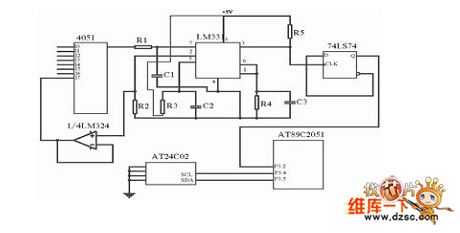
Multi-Channel Voltage Patrol Detecting(NE555,CD4066) Circuit Diagram
Published:2011/6/21 6:15:00 Author:Vicky | Keyword: Multi-Channel Voltage Patrol Detecting

View full Circuit Diagram | Comments | Reading(3402)
Circuit Diagram of Frequency Shift Demodulator Composed of CA3020 and MC723
Published:2011/6/21 6:26:00 Author:Vicky | Keyword: Frequency Shift Demodulator
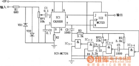
IC1 is a broadband amplifier CA3020 which constitutes input stage of circuit. It’s differential out is connected to input ends J &K of IC2 (JK trigger MC723). Gate circuit IC3 constitutes monostable multivibrator, with a timing cycle equaling with 1/2 center frequency cycle. The input signal will strobe the trigger after going through monostable multivibrator. For example, If 2920Hz represents symbol and 2750Hz represents blank space, then the center frequency is 2835Hz, therefore the cycle of monostable multivibrator is 175μs. When the input signal is 2920Hz, and the trigger strobe end is J=1, and K=0, then the Q end’s output is 1”1” (representing symbole); when the input signal is 2750Hz, and the trigger strobe is J=0 and K=1, then the Q end’s output is “0” (representing space). The detection accuracy of the circuit is determined by the timing accuracy of monostable multivibrator multivibrator. (View)
View full Circuit Diagram | Comments | Reading(741)
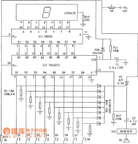
Circuit Diagram of Eight-Way Answer Device composed of CH233 and 74LS273
Published:2011/6/25 10:39:00 Author:Vicky | Keyword: Eight-Way Answer Device
View full Circuit Diagram | Comments | Reading(1249)
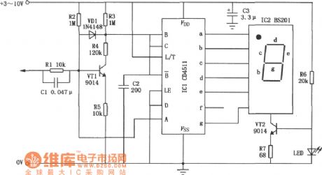
Circuit Diagram of Four-State Logic Displaying Pen composed of CD4511
Published:2011/6/25 10:40:00 Author:Vicky | Keyword: Four-State Logic Displaying Pen
View full Circuit Diagram | Comments | Reading(3929)
Circuit Diagram of Week Digital Dispaly composed of CH233 and CD4017
Published:2011/6/26 8:08:00 Author:Vicky | Keyword: Week Digital Dispaly
View full Circuit Diagram | Comments | Reading(464)
Road Night Auto Electronic Guidepost Circuit Diagram
Published:2011/6/21 6:45:00 Author:Vicky | Keyword: Road Night Auto Electronic Guidepost
Auto electronic guidepost’ circuit diagtam is shown as in the picture. When night falls, the indicator light E3 gives out red light, warning that the section is dangerous. When there is vehicle getting close to the dangerous section, the traffic sign composed of indicator lights E1 and E2 is shown and meanwhile indicator E3 and E4 sparkle, giving out red and green light respectively. When the vehicle drives away, the indicator E3 keeps giving out red light, while indicator E1, E2 and E4 go out. The circuit is mainly composed of sound-control circuit, oscillating circuit and display driving circuit etc. (View)
View full Circuit Diagram | Comments | Reading(1061)
Ball Game Scoring Device (CD4027,CD4055,CD40192) Circuit Diagram
Published:2011/6/25 10:39:00 Author:Vicky | Keyword: Ball Game Scoring Device
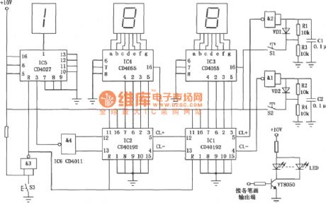
Ball game scoring device’s circuit is as shown in the picture. It is used to record and display the performance of a ball game. The first Nixie tube has only two states, that is extinguishing or displaying “1”; the next two Nixie tube can display ten states from 0 to 9. Therefore, the maximum scoring of the scoring machine can reach 199. The circuit is mainly composed of scoring circuit, decoding circuit, trigger decode, displaying circuit and anti-vibration switch circuit. (View)
View full Circuit Diagram | Comments | Reading(6394)
Telephone Voice Recorder (CD4511B, VCD4518B) Circuit Diagram
Published:2011/6/25 10:42:00 Author:Vicky | Keyword: Telephone Voice Recorder
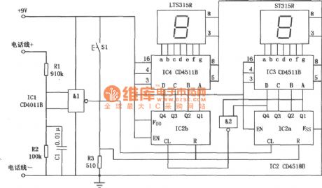
Telephone voice recorder circuit is as shown in the picture. It is mainly used to record and display the numbers that the telephone is used in one day to help people get to know the usage situation of the telephone. The recorder is composed of two seven-segment Nixie tube, therefore the maximum recording number is up to 99. There is reset button in the circuit which can clear the records. (View)
View full Circuit Diagram | Comments | Reading(2069)
Proximity Detector (LM385) Diagram Circuit
Published:2011/6/26 18:56:00 Author:Vicky | Keyword: Proximity Detector
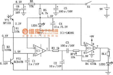
Proximity detector circuit is shown in the above picture. The circuit adopts ordinary phototube to detect the illumination changes when people enters alert zones, and thereby realize detecting function. (View)
View full Circuit Diagram | Comments | Reading(2157)
Voltage stabilization power supply performance index test circuit
Published:2011/6/22 2:12:00 Author:TaoXi | Keyword: Voltage stabilization, power supply, performance, index, test circuit
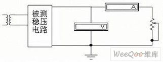
The voltage stabilization power supply has two kinds of technology index: the first one is the characteristic index, it includes the input voltage, the output voltage, the output current and the output voltage adjustment range.etc; the other one is the quality index which can be used to measure the stability of the output DC voltage, it includes the voltage regulation coefficient (or the voltage adjustment rate), the output resistance (or the current adjustment rate), the ripple voltage (ripple coefficient) and the temperature coefficient. The test circuit is as shown in the figure.
(View)
View full Circuit Diagram | Comments | Reading(497)
Light interrupt detector circuit
Published:2011/6/22 3:12:00 Author:TaoXi | Keyword: Light interrupt, detector
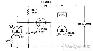
When the light which projects on the light-excited SCR interrupts, the voltage of the single-pole switch 2N4990's anode tends to the forward direction in next positive half-cycle. When the voltage reaches to the open voltage of the unidirectional switch, it triggers the unidirectional switch and the SCR C230B. As long as the light does not shine on the light-excited SCR, the load will be stimulated.
(View)
View full Circuit Diagram | Comments | Reading(776)
A low-cost but precise temperature test circuit
Published:2011/6/26 21:40:00 Author:Borg | Keyword: low-cost, precise, temperature test circuit
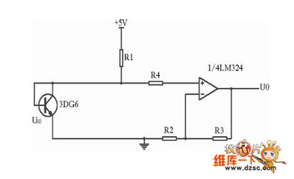
With 3DG6 as the temperature sensor, the test amplifier composed of the LM324 op-amp is shown in figure 1. The transistor 3DG6 is located in the test spot, and its basic pole is short with its collecting electrode, i.e the emitting positive bias, the collecting knot 0 bias is used as the temperature sensor, the power supply provides with 45mA collecting electrode current for 3DG6 with the help of resistor R1 (100K). Its UBE is connected with the non-inverting terminal of LM324, all R1, R2, R3 and R4 are ordinary metal film resistors, if R2=R3,the output of the amplifier will be U0≈2UBE. In the device, both the 2 chips of LM324 can detect the input signal of 7 lines.
(View)
View full Circuit Diagram | Comments | Reading(779)
Ten-Channel Temperature Patrol Detecting Circuit Diagram
Published:2011/6/26 1:03:00 Author:Vicky | Keyword: Ten-Channel Temperature Patrol Detecting
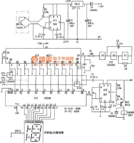
Temperature Sensor adopts 3AX31 and is in the form of diode. When the temperature changes, the resistance K presents linear variation.
Oscillator is composed of IC1 (555), rce, R1, and C1 etc. The frequency is: f=1.44/(R1+2rce)C1. Therefore, the rce presents linear variation with the changing of temperature, and f also varies proportionally to realize the conversion of temperature and frequency. If ten spots are to be tested, then 10 temperature-frequency converters are needed.
In the circuit, IC2 adopts hex inverter CD4069, and F1,F2,F3 make up trigger generator of 0.2 Hz, that is to send a count pulse CP to the count circuit IC3 every 5 seconds. (View)
View full Circuit Diagram | Comments | Reading(606)
Bearing fault detector 1
Published:2011/6/24 7:48:00 Author:Nicole | Keyword: bearing fault, detector
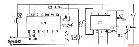
The bearing fault detector circuit is composed of bearing testing sensor, signal process circuit IC1, LED VL, transistor V, audio amplifier integrated circuit IC2, soudspeaker BL and some relevant resistor capacitor components, it is shown in the figure 8-78.
After the power supply switch S is turned on, IC1 works, its 4 foot and 12 foot all output high level, V is turned on, VL is lighted, then IC2's 3 foot has no input signal, loudspeaker BL does not phonate.
RP1 is used to adjust the sensitivity of signal process circuit.
RP2 is used to regulate the loudspeaker's output volume.
(View)
View full Circuit Diagram | Comments | Reading(686)
Bearing fault detector 2
Published:2011/6/24 7:57:00 Author:Nicole | Keyword: bearing fault, detector
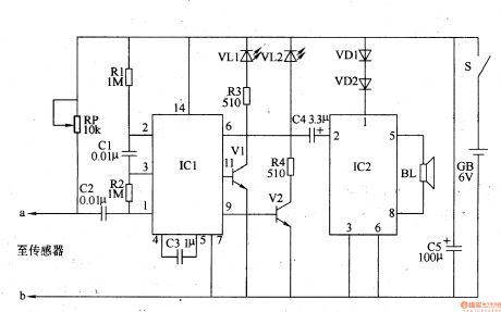
The bearing fault detector circuit is composed of bearing testing sensor, signal process circuit and acousto-optic circuit, it is shown in the figure 8-79.
The signal process circuit is made of input socket XS, sound control integrated circuit IC1, capacitors C1-C3, resistors R1, R2 and potentiometer RP.
The acousto-optic circuit consists of transistors V1, V2, LED VL1, VL2, audio power amplifier integrated circuit IC2, resistors R3, R4, capacitor C4, diode VD1, VD2 and loudspeaker BL.
The sensor's sensitivity can be changed by adjusting RP.
(View)
View full Circuit Diagram | Comments | Reading(835)
Automatic charging detection circuit and the indicating circuit
Published:2011/6/21 20:12:00 Author:TaoXi | Keyword: Automatic charging, detection circuit, indicating circuit
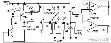
As the figure shows, the automatic power-off circuit is composed of the transistor VT2, the voltage follower A1, the voltage comparator A2, the resistors R4, R5, R6, R7, R8, R11 and the variable resistor RP1. When the charging begins, the voltage comparator outputs the high level, the VT1 and VT2 conduct, the LED indicator light turns on, the power charges the battery. You can preset the stage 1 of the change-over switch means to charge a battery, the stage 2 of the change-over switch means to charge two batteries, so you can realize to charge for the 1-4 batteries. When the batteries are full, the voltage comparator outputs the low level, the VT2 cuts off, the VT1 will not conduct, the LED turns off, the charging is over.
(View)
View full Circuit Diagram | Comments | Reading(678)
The principle circuit of production line workpiece counting device
Published:2011/6/11 21:32:00 Author:qqtang | Keyword: principle circuit, production line
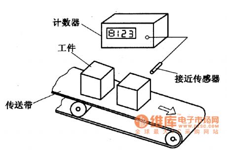
The counting of production line workpieceIn the figure is principle circuit of production line workpiece counting device. The approaching sensor is fixed at one side of the workpiece band carrier, when the band carrier is working, the workpieces are crossing the sensor. And when the workpieces are getting close to the sensor, the sensor is outputting switch signals, and the signals will be sent to the counter.
Figure: The principle circuit of production line workpiece counting device (View)
View full Circuit Diagram | Comments | Reading(812)
The working principle circuit of product length measuring
Published:2011/6/11 21:24:00 Author:qqtang | Keyword: working principle, product length measuring
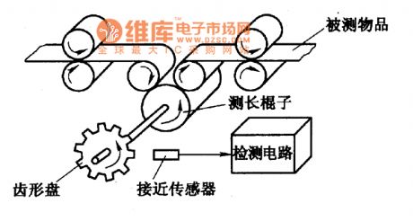
When producing the varnished wire, steel beginning,steel belt and cloth, we can use the method in the figure to measure the length of the products. The measuring ruler and the sawtooth plate are fixed in the same axis, the approaching sensor is on the side of the plate. If the tooth number of the plate is N, then for each round that the plate rotates, the sensor outputs N pulses. At the moment, the measuring ruler which has the same axis with the plate also rotates a round, it means the length of a round of the matter under test is π.D, so the lengths corresponding to each pulse are:
(View)
View full Circuit Diagram | Comments | Reading(554)
| Pages:91/101 At 2081828384858687888990919293949596979899100Under 20 |
Circuit Categories
power supply circuit
Amplifier Circuit
Basic Circuit
LED and Light Circuit
Sensor Circuit
Signal Processing
Electrical Equipment Circuit
Control Circuit
Remote Control Circuit
A/D-D/A Converter Circuit
Audio Circuit
Measuring and Test Circuit
Communication Circuit
Computer-Related Circuit
555 Circuit
Automotive Circuit
Repairing Circuit