
Measuring and Test Circuit
Index 96
The LEV tester circuit of the resistor set high/low electric detecting threshold
Published:2011/6/7 1:57:00 Author:qqtang | Keyword: LEV tester, detecting threshold
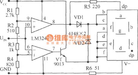
In the figure is the LEV tester circuit of the resistor(R1~R4) set high/low electric detecting threshold. The threshold voltage can be calculated by voltage distributing formula, when the value is adapted by R1~R4, the LEV threshold of 9-pin is 2.5v, the LEV threshold of 5-pin is 0.8v. When UIN≤0.8V, 7-pin outputs a high LEV, TV is conducting, the it indicates 0 ; when UIN≥2.3V, 8-pin outputs a high LEV, and it indicates 1 , the decimal dp is glowing; when UIN inputs a clock pulse, it indicates a 0 with points; when UIN is in 0.8V~2.3V, both 7 and 8 output low LEV. (View)
View full Circuit Diagram | Comments | Reading(782)
true RMS RF power measurement system composed of a monolithic true RMS power measurement system AD8362 circuit
Published:2011/6/9 4:56:00 Author:John | Keyword: true RMS RF power measurement system
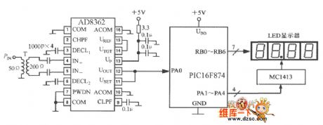
True RMS RF power measurement system composed of a monolithic true RMS power measurement system AD8362 circuit is shown below.
(View)
View full Circuit Diagram | Comments | Reading(2841)
RF power control system composed of a monolithic true RMS power measurement system AD8362 circuit
Published:2011/6/9 4:56:00 Author:John | Keyword: RF power control system
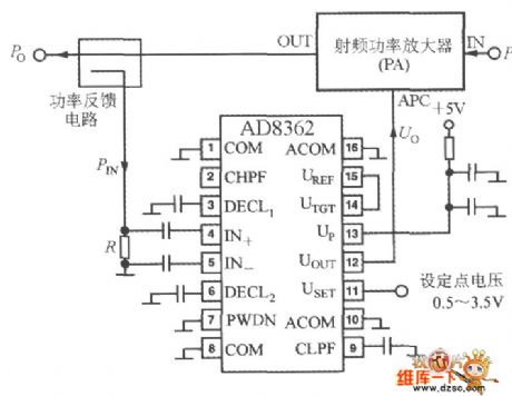
RF power control system circuit constituted by the AD8362 is just as shown in the figure. At this moment, set point voltage USET is input on pin 11 with a voltage range from 0.5V to 3.5V. Controlled system is RF power amplifier (PA). Propose the input power of PA as PI and the output power as Po. Po changes according to the with the control voltage Uo added on console termianal of APC. Utilize the power feedback circuit to form a control loop, so that the output power of PA is equal to the setting. PIN is the feedback power and R is the feedback power’s sampling resistance.
(View)
View full Circuit Diagram | Comments | Reading(760)
The tester circuit of transistor and common cathode digital pipe
Published:2011/6/6 23:40:00 Author:qqtang | Keyword: tester circuit, transistor, common cathode
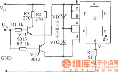
See as the figure, the positive power supply Vcc and the ground terminal GND are connected with the circuit under test by a clamp, the UIN pole is linked to the tested point by a probe.when the tested point is in a high LEV, VT1 is conducting, the h,c and g are in high LEV and glowing, and the e and f are glowing by separating pipe VD1 at the same time, the digital pipe indicates a H ; when the tested point is in a LEV, VT2 is conducting,and d,e and f are glowing, a 1 is shown. VD1 and VD2 fulfill the separating functions, and complete the functions of logic OR (which can be substituted by a second input terminal). (View)
View full Circuit Diagram | Comments | Reading(568)
Single-chip Temperature Sensor Circuit
Published:2011/5/16 22:04:00 Author:Sharon | Keyword: Single-chip, Temperature Sensor
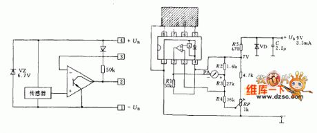
IC LM3911 is a silicon sensor constituted by the operational amplifier and constant voltage circuits. Just adding a small number of external components can form a simple electronic thermometer. There is transistor in the silicon used as sensitive device. Transistor base-emitter voltage changes with temperature. When the temperature rises, the base-emitter voltage is also increased. Temperature obtained from a copper block is delivered to the temperature sensor, in the condition that the copper block is linked to pin 5~8. These pins are internally connected to the temperature sensor. Temperature sensor constant voltage source (6.8V) provides power supply. Signals output from the temperature sensor is added to the input in the same direction with the internal operational amplifier, and its potential inverting input is fixed.Therefore, the potential of the operational amplifier output (Pin 2) is controlled by temperature sensor, with the meter indicating the reading.
Integrated chip in the circuit needs current about 3mA, and other 0.5mA current passes through the external circuit.
The operating temperature range of temperature sensor is -25 ℃ ~ +85 ℃. That indicates the scope is decided by external circuit parameters.
(View)
View full Circuit Diagram | Comments | Reading(627)
Soil humidity tester circuit
Published:2011/5/30 1:27:00 Author:Christina | Keyword: Soil, humidity, tester
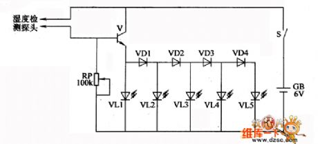
The circuit principle: this soil humidity tester circuit is composed of the humidity detection probe, the transistor V, the diodes VDl-VD4, the LEDs VLl-VL5, the potentiometer RP, the power switch S and the battery GB. When the humidity detection probe is not in the soil or the soil is too dry, the V and the VDl-VD4 are in the cut-off state, VL1~VL5 do not emit light. When the soil has certain humidity, the soil moisture makes the resistance between the two electrodes of the humidity detection probe lower and lower, V conducts, VLl-VL5 turn on one by one. The greater the soil moisture is, the stronger the V conduction capacity is, the more number of LEDs will turn on.
(View)
View full Circuit Diagram | Comments | Reading(1328)
Thermocouple temperature measurement circuit with the cold contact point compensation
Published:2011/5/26 8:22:00 Author:Christina | Keyword: Thermocouple, temperature measurement, cold contact point, compensation
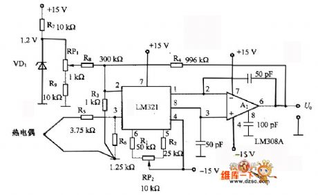
The thermocouple temperature measurement circuit with the cold contact point compensation is as shown. This circuit is composed of the preamplifier LM321 and the operational amplifier LM308A. The LM321 has the temperature characteristic of lμV/℃. If the maladjustment voltage is zero, the temperature drift is zero too; if there is the maladjustment voltage, it will produce the temperature drift, this temperature drift can be used in the thermocouple's cold contact point compensation.
(View)
View full Circuit Diagram | Comments | Reading(2656)
Xunda VFP elevator maintenance circuit
Published:2011/6/2 1:43:00 Author:TaoXi | Keyword: Xunda, elevator, maintenance
Xunda VFP elevator maintenance circuit (View)
View full Circuit Diagram | Comments | Reading(605)
Oil pressure display circuit
Published:2011/5/26 1:33:00 Author:Christina | Keyword: Oil pressure, display circuit
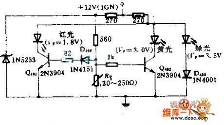
The sensor changes the oil pressure into the variable resistance RT. The variation of RT changes the bias voltage of each crystal transistor, the three LEDs (red, yellow and green) light in different positive biases. So we can ensure that every time there is only one light-emitting diode shining to indicate the corresponding hydraulic.
(View)
View full Circuit Diagram | Comments | Reading(612)
Identifying the same polarity of the coil
Published:2011/5/30 4:10:00 Author:Seven | Keyword: same polarity

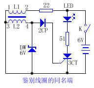
76.identifying the same polarity of the coilIf we want to know the same polarity of the primary and second stage coil in a transmitter, we can judge by using identifiers which consists of elements like controllable silicons, etc. See as the circuit, it is designed according to the conducting condition of controllable silicons. At the moment of power-on, the primary coil L1 is generating sensing LEV of which the left is negative and the right is positive. If 1 and 3 are the same polarity, the pole of 3 will sense a positive LEV, put the two positive LEV on the positive pole and control stage,respectively, then the controllable silicon is conducting and the LED is glowing.
(View)
View full Circuit Diagram | Comments | Reading(779)
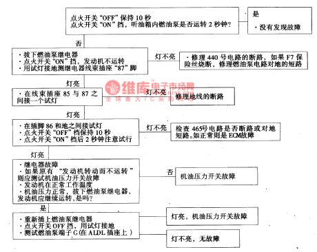
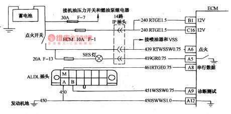
The oil pump relay circuit of Daewoo-ESPERO
Published:2011/5/18 21:03:00 Author:Borg | Keyword: oil pump relay, Daewoo-ESPERO
6.The diagnosis on the fault of rotating engine without runningThe so-called rotating engine without running means that the engine can rotate driven by the stater but can not automatically run. Before we judge the fault, we should make sure the battery has enough power, and the stating speed of the engine is normal, there is enough oil in the box. The circuit is shown in Figure 13, and the diagnosis course marks of * are introduced as follows.*1 the lighting of repair the engine immediately indicator means the power supply voltage and igniting voltage of 5V have been transmitted to ECM.
(View)
View full Circuit Diagram | Comments | Reading(805)
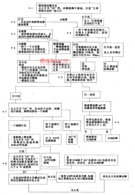
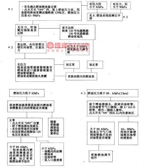
The fault diagnosis circuit of Daewoo ESPERO fuel system
Published:2011/5/18 4:35:00 Author:Borg | Keyword: diagnosis circuit, fuel system
When the switch is on, start the engine and it begins to run, then ECM will receive the reference pulse from HEI electricity distributor,If there is no reference pulse, ECM will shut down the oil pump in 2 seconds after the igniting switch is on. The fuel pump will give the throttle injector a pressure of 62~9OkPa(9~13psi), and the spare oil will go back to the oil box.The fuel pump test pin is on the left side of the engine cylinder, and when the engine is stalling, it will impose a battery voltage on the pin so that the pump will work temporarily.
(View)
View full Circuit Diagram | Comments | Reading(1347)
555 fatigue degree tester circuit
Published:2011/5/24 1:53:00 Author:TaoXi | Keyword: fatigue, degree, tester circuit
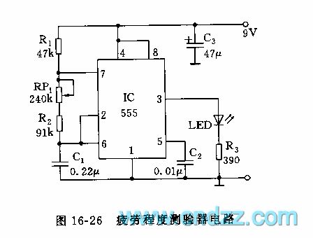
As the figure 16-26 shows, the astable multivibrator is composed of the 555 and R1,R2,RP1,C1, the oscillation frequency f=1.44/(R1+RP1+2R2)C1.
The principle of the fatigue degree tester is based on the visual eye temporarily leave phenomenon of human eyes. The average person under the normal conditions, the eyes can sense the continuous light with the frequency of 30~40Hz. When you are fatigue or drinking too much, the perception frequency will reduce. The figure parameter's oscillation frequency is about 20~60Hz, you can adjust the RP1 to make the frequency of 35Hz, when you are fatigue, the LED will start flashing.
(View)
View full Circuit Diagram | Comments | Reading(749)
The power test circuit
Published:2011/5/22 0:50:00 Author:Borg | Keyword: power test
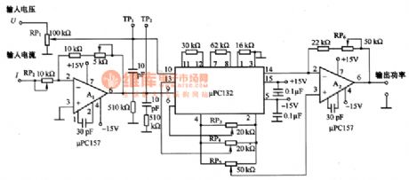
The figure is a power test circuit. Power is equal to voltage multiplies current. The circuit is formed by a multiplier of μPCl32. The input voltage is imposed on the 10 pin interface through RP1(electricity distributor), and the input current is imposed on the 9-pin of μPCl32 after being magnified. The power is delivered out by A2 after the input current multiplies the input voltage. By the way, the max voltage on the 9 and 10 pins can be higher than ±lOV, which could be set by the resistances of RP1 and RP2.When adjusting, connect the 10-pin of the voltage input terminal with the ground at first. (View)
View full Circuit Diagram | Comments | Reading(744)
The liquid concentration measuring circuit
Published:2011/5/22 1:08:00 Author:Borg | Keyword: liquid concentration, measuring circuit
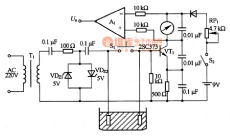
This is a liquid concentration measuring circuit. The principle of the circuit is that to insert two poles in the liquid, and get the voltage, then the concentration of the liquid is indicated by the meter. The AC voltage is reduced by the transistor of T1, and then is change into a square wave potential after passing VDZ1 and VDZ2, the stabilizers. Thus, the AC voltage is hold by the stabilizer tube, and the change of power supply wouldn't affect the measured circuit. The square wave potential is imposed on the base electrode of VT1 by the pole, and it changes with the concentration of the liquid.
(View)
View full Circuit Diagram | Comments | Reading(647)
The diagnosis circuit of Daewoo ESPERO fault code of 14
Published:2011/5/18 1:54:00 Author:Borg | Keyword: diagnosis circuit, Daewoo ESPERO
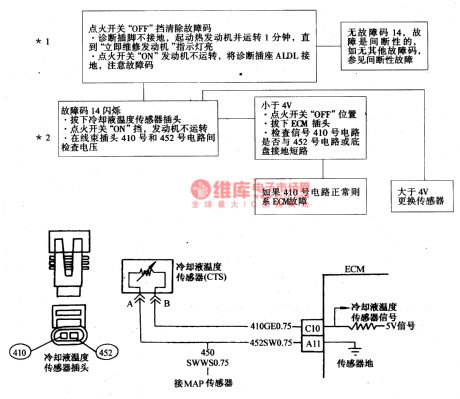
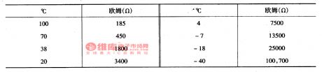
The code of 14 means that that the signal voltage of coolant temperature sensor is low--indicating high temperature(see as Figure 4 and Figure 16). The coolant temperature sensor controls the ECM signal with a thermistor. Firstly , ECM imposes a voltage on the sensor in No.410 circuit, when the engine becomes cool, the resistance of the sensor(thermistor) is getting high, then ECM will detect a high signal voltage. When the engine is getting hotter, the resistance of the sensor is becoming low, the voltage is coming down. When at the normal engine temperature, the ECM pin of C10 will get the voltage of 1.5~2.0V.
(View)
View full Circuit Diagram | Comments | Reading(1103)
8051 SCM basic working circuit
Published:2011/5/19 19:46:00 Author:Christina | Keyword: SCM, basic working circuit
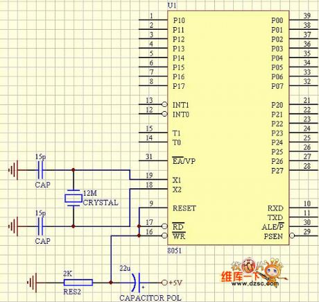
8051 SCM basic working circuit
(View)
View full Circuit Diagram | Comments | Reading(1254)
The circuit of fault repairing on the unlighted engine service indicators of Daewoo-ESPERO
Published:2011/5/19 0:02:00 Author:Borg | Keyword: fault repairing, engine service indicators, Daewoo-ESPERO
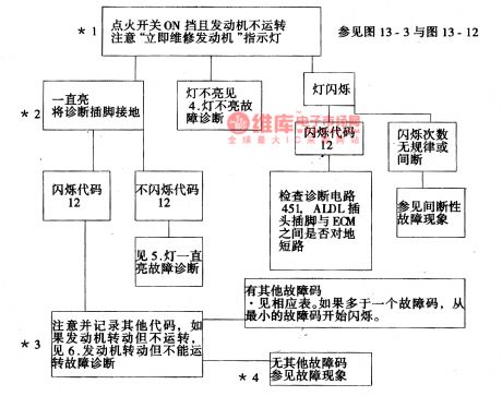
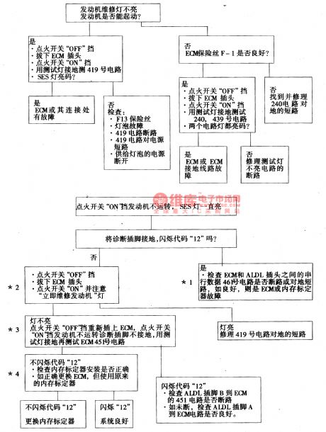
3.test on diagnosis circuitIn Figure 3 and Figure 4, to find out the fault with the help of fault diagnosis light (SES), we should know the diagnosis circuit is all right at first, if it is ,then the engine willbe still when the igniting switch is on, but the light is glowing. To diagnosis outlet ground connection in the above way, we should flash the code of 12 for 3 times at first , and then flash other codes. If others are all right,then flashthe code of 12repeatedly, the checking course is as follows.
(View)
View full Circuit Diagram | Comments | Reading(791)
The flash sequence of code 34 of Daewoo
Published:2011/5/18 21:36:00 Author:Borg | Keyword: flash sequence, Daewoo
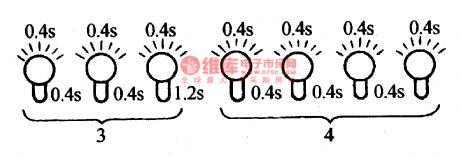
Fault code list:Code of 14--coolant temperature circuit(indicating high temperature)Code of 15--coolant temperature circuit(indicating low temperature)Code of 21--TPS circuit (high signal voltage )Code of 21--TPS circuit (low signal voltage )Code of 23--MAT sensor circuit (temperature is too low)Code of 24-- VVS circuitCode of 25-- MAT sensor circuit (temperature is too high)
(View)
View full Circuit Diagram | Comments | Reading(602)
Transmitter principle circuit
Published:2011/5/16 3:26:00 Author:Christina | Keyword: Transmitter, principle
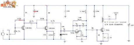
The Transmitter principle circuit is as shown:
(View)
View full Circuit Diagram | Comments | Reading(759)
| Pages:96/101 At 2081828384858687888990919293949596979899100Under 20 |
Circuit Categories
power supply circuit
Amplifier Circuit
Basic Circuit
LED and Light Circuit
Sensor Circuit
Signal Processing
Electrical Equipment Circuit
Control Circuit
Remote Control Circuit
A/D-D/A Converter Circuit
Audio Circuit
Measuring and Test Circuit
Communication Circuit
Computer-Related Circuit
555 Circuit
Automotive Circuit
Repairing Circuit