
Measuring and Test Circuit
Index 90
Non-Transformer Type Product Detection (MC1596G) Circuit Diagram
Published:2011/7/1 23:59:00 Author:Vicky | Keyword: Non-Transformer, Product Detection
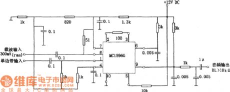
The above picture is a non-transformer type product detection circuit. The circuit uses MC1596G instead of LC resonance and transformer. The circuit is available in a frequency range from low frequency to a relative wide frequency of 100MHz, that is to say, it works by changing the parameter of RC low part filter in output part. The circuit is available in Mixer, Frequency Doubler, and modulator etc. (View)
View full Circuit Diagram | Comments | Reading(825)
Circuit Diagram of Photoelectronic Pulse Omission Detection Composed of 556
Published:2011/7/2 1:03:00 Author:Vicky | Keyword: Photoelectronic Pulse Omission Detection
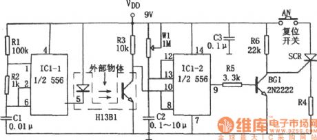
There is a several millimetric slit between the luminotron and photosensitive tube inside photoelectronic switch H13B1. When light-isolator object from outside is plugged into the slit, the photosensitive tube inside H13B1 presents high impedance because of the cutting-off of the beam of light. Then the IC1-2(1/2 556) sends out high level because that the pulse signal detection cannot receives reset signal, and it turns into a transient stability state. The correspondent transient stability time is td=1.1RwlC2 and the td can be changed by modulating W1. If the signal interrupting duration is longer than the transient stability time, IC1-2 resets, pin ③ sends out low level which stops BG1, SCR is conducted and the load RL is correspondently conducted. It will either cut down the power supply circuit or send out alarming signal. (View)
View full Circuit Diagram | Comments | Reading(723)
Photoelectric-Type Auto-Counting Device Circuit Diagram
Published:2011/6/23 8:49:00 Author:Vicky | Keyword: Photoelectric-Type Auto-Counting Device

The principle of photoelectric-type auto-counting device is shown in the picture. It is made of single chip microcomputer PIC16C57, which is applicable to industry automatic control of product line and of certain practical value. (View)
View full Circuit Diagram | Comments | Reading(1801)
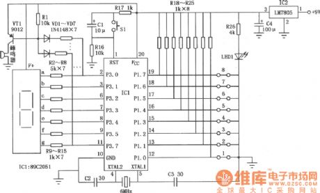
Circuit Diagram of digital eight-way disconnection detector composed of monolithic 89C2051
Published:2011/6/23 8:44:00 Author:Vicky | Keyword: digital eight-way disconnection detector
View full Circuit Diagram | Comments | Reading(651)
Thyristor Work Performance Quick Test Circuit Diagram
Published:2011/6/26 6:12:00 Author:Vicky | Keyword: Thyristor Work Performance Quick Test
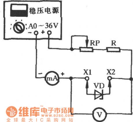
Plug the diode VD under test into sockets X1 and X2. Stabilized power supply adds reverse breakdown voltage to VD and the stabilized voltage value Uz can be read from voltage meter V, and the stable-working current value can be read from the milliammeter mA which is cascaded in the circuit. The indicating value in the mA will varies with the regulation of potensiometer RP. Observe the changing of the voltage meter, the less the stabilized value Uz changes, the better. (View)
View full Circuit Diagram | Comments | Reading(1510)
Semiconductor Diode Detecting Circuit Diagram
Published:2011/6/26 4:22:00 Author:Vicky | Keyword: Semiconductor Diode Detecting Circuit
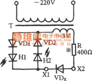
Semiconductor diode is often used in electrical engineering circuit. Once the original diode breaks, it should replaced. Whether the new diode is good or not can be judged in the way as the picture shows. As shown in the picture, T is a 220/3V-2W power transformer, VD1 & VD2 are 2CP10 rectifier diodes, H1 & H2 are luminous diodes, and VDX is a diode under test. During the testing, plug the VDX into sockets X1 &X2. If only one luminous diode sends out light when the power is on, then the diode is good; however, if H1 & H2 both are luminous, it indicates that the VDX suffers internal short-circuit; if both are lightless, it indicates that the diode suffers internal open-circuit. (View)
View full Circuit Diagram | Comments | Reading(904)
Straight-Flow Capacitance Tester Circuit Diagram
Published:2011/6/16 10:56:00 Author:Vicky | Keyword: Straight-Flow Capacitance Tester
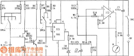
The above picture is a straight-flow capacitance tester. The test is composed of pulse generator, monostable trigger, DC amplifier ( direct current amplifier) and head indicating circuit etc. It can test capacitance from npF to 10μF. The distance is from to 100PF, from 0 to 1nF, from o to 10nF, from 0 to 100nF,from 0 to 1μF, and from 0 to 10μF. (View)
View full Circuit Diagram | Comments | Reading(877)
Circuit Diagram of Capacitance/Frequency/Transistor Online Detector composed of 555
Published:2011/6/26 1:05:00 Author:Vicky | Keyword: Capacitance/Frequency/Transistor Online Detector
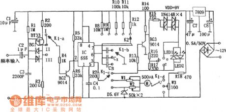
When K1 is placed in II, then it can be used to test capacitance. 555, resistances from R8 to R12 and Capacitance Cx under test constitute monostable timing circuit. The larger the capacity of Cx is, the wider the pulse is. That is to say, if td=1.1(R8~R12)Cx is larger, the average current value is larger, and the indication of correspondent header is larger. In the circuit, BG1 is a unijunction transistor, and constitutes relaxation oscillator together with R1 and C3. Its output oscillator pulse signal is the trigger pulse of IC.
When K1 is place in III, it can be used to test frequency. Under such circumstance, monostable circuit IC sends out fixed-width-value signal (td'=1.1(R8~R12)CB).
When K1 is place in I, it can be used to test transistor. Transistor BG1 is responsible for the conversion of the positive and negative power. (View)
View full Circuit Diagram | Comments | Reading(903)
Catoptric-Strength Testing Circuit (CD4052B,CD40118) Diagram
Published:2011/6/26 1:01:00 Author:Vicky | Keyword: Catoptric-Strength Testing Circuit
When the circuit works regularly, make the infrared luminous diode (LED) out of light, the photodiode changes the received exterior interference signal into electrical signal, and then pass it to negative-direction integration circuit. Suppose this procession takes time of T1. Next, make the LED give out light, the photodiode changes the received photosignal into electrical signal and then pass it to positive –direction integrator circuit. Suppose this procession takes time of T2. Suppose T1=T2. Then the held signal the circuit displays is not relevant with exterior disturbing, but only relevant to the strength of the catoptic. Time of holding the signal is called holding time and marks it as T3. The reset time of correspondent integrator is T4. (View)
View full Circuit Diagram | Comments | Reading(1300)
Radio Digit-Type Frequency Display (C040,556) Circuit Diagram
Published:2011/6/26 0:56:00 Author:Vicky | Keyword: Radio Digit-Type Frequency Display
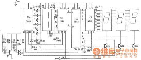
The above picture is radio digit-type frequency circuit diagram. The circuit is double time based circuit 556(IC1), BCD-code three-digit counter IC2(MC4553), twelve binary-system serial counter/frequency-divider IC4(C040), BCD-code seven-phase latch/ decoder/driver, four luminous Nixie tube LED etc. (View)
View full Circuit Diagram | Comments | Reading(2408)
Circuit Diagram of Audio Frequency Indicator (FD502) Composed of Five-Digit LED Display
Published:2011/6/26 0:55:00 Author:Vicky | Keyword: Audio Frequency indicator, Five-Digit LED Display
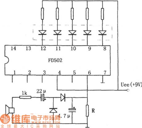
The above picture is a circuit diagram of audio frequency indicator (FD502) which is composed of five-digit LED display. The circuit constitutes a level meter driver FD502 and a five-digit LED display. The circuit can generate DC level by extracting the positive variation amplitude, and thereby indicate the audio frequency. If the audio signal is too low, use FD501 to replace FD502 and then drive LED after preamplification. FD502and FD501 are domestic integrated circuits. FD501 has one preamplifier and 5 comparators inside, while FD502 has no preamplifier. (View)
View full Circuit Diagram | Comments | Reading(1196)
Acousto-optic Controlling Electronic Guidepost Circuit Diagram
Published:2011/6/23 8:51:00 Author:Vicky | Keyword: Acousto-optic Controlling Electronic Guidepost Circuit Diagram
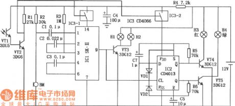
Automatic guidepost circuit is shown in the above picture. It is mainly made of sound-controlling circuit, oscillating circuit and display driving system etc. (View)
View full Circuit Diagram | Comments | Reading(567)
Luminous Logic Pen Circuit Diagram
Published:2011/6/16 10:58:00 Author:Vicky | Keyword: Luminous Logic Pen
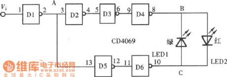
Logic pen is also called as logic test probe, which is a commonly-used tool in testing the logic states of the dots in a digital circuit. The logic states in a digital circuit can be divided as high level ‘1’, low level ‘o’ and high impedance state (infloating). The test results of the logic states can be displayed by a luminous diode, or an acoustical generator, or a digital luminous diode. The above picture is a logic test pen composed of hex-inverter CD4069 and luminous diode. (View)
View full Circuit Diagram | Comments | Reading(993)
Sound-Type Logic Pen Circuit Diagram
Published:2011/6/16 10:57:00 Author:Vicky | Keyword: Sound-Type Logic Pen

The result of sound-type logic pen is observed by naked eyes. Due to the high development of modern electronics producing technology, soldered dots are densely assigned in the circuit board. Therefore when testing, one should concentrate on it and his eyes should always focus on the tested dot. Hence if a sound-type tester is made, our ears can be also used in testing and it will highly improve the efficiency. The above picture ia the sound-type logic pen composed of NAND gate CD4011. (View)
View full Circuit Diagram | Comments | Reading(764)
Metal Detector (MC14046-B) Circuit Diagram
Published:2011/6/23 8:42:00 Author:Vicky | Keyword: Metal Detector Circuit
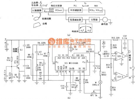
Metal Detector is shown in the above picture. Detection coils constitute the LC oscillating circuit. When the coil gets close to the metal, the metal will generate eddy current inside, change the amount of coil inductance and thereby change the oscillating frequency of the detector circuit. Picture(a) is the functional block diagram of the detector and picuture(b) is the detecting picture. (View)
View full Circuit Diagram | Comments | Reading(3650)
Simple light intensity meter circuit
Published:2011/6/30 3:48:00 Author:Christina | Keyword: Simple, light intensity, meter circuit
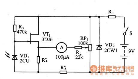
The simple light intensity meter circuit is as shown in the figure. The electric bridge circuit is composed of the VT1, R4, R5 and RP1. When there is no illumination, the adjustment potentiometer RP1 makes the balance of the bridge, and there is no current on the ammeter, the ammeter pointer indicates to zero. When the light irradiates on the photosensitive diode VD1, the photodiode shows the different resistances with the different light intensities, so the field effect current flows through the ammeter, the pointer deflects.
Figure: Simple light intensity meter circuit (View)
View full Circuit Diagram | Comments | Reading(2347)
Vizi saloon car combination meter circuit
Published:2011/6/30 19:32:00 Author:TaoXi | Keyword: Vizi, saloon car, combination meter
The Vizi saloon car combination meter circuit is as shown in the figure:
(View)
View full Circuit Diagram | Comments | Reading(665)
Potential isolated current measurement circuit
Published:2011/6/30 20:00:00 Author:TaoXi | Keyword: Potential, isolated, current measurement
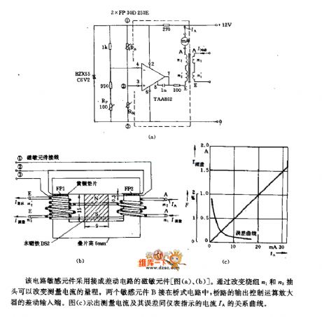
This circuit sensitive component is connected into the magnetic susceptibility component of the differential circuit. By changing the taps of winding n1 and winding n2, you can change the measuring range of the measuring current. The two sensitive components B are connected in the bridge type circuit, the output of the bridge type circuit controls the differential input port of the operational amplifier. Figure (c) shows the relation curve between the measuring current and the measurement error meter indicating current IA.
(View)
View full Circuit Diagram | Comments | Reading(855)
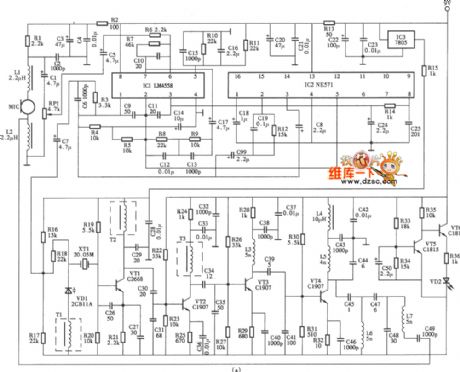
The MacsotMR700 wireless microphone circuit
Published:2011/6/28 0:24:00 Author:Borg | Keyword: wireless microphone
View full Circuit Diagram | Comments | Reading(2702)
Infrared detector circuit
Published:2011/6/28 3:09:00 Author:Christina | Keyword: Infrared detector
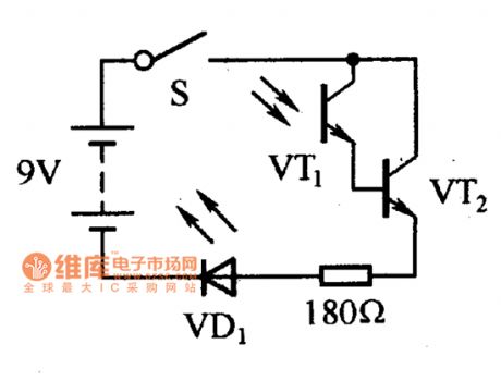
The infrared detector circuit can be used to detect whether the infrared remote control transmitter device is working properly. The infrared detector circuit is as shown in the figure. When the infrared remote control transmitter outputs the infrared light to irradiate the photosensitive transistor VT1, the resistance decreases to drive the conduction of VT2, so the light-emitting diode VD1 is lighted with the rhythm of the incident light. Because the brightness of the light-emitting diode VD1 depends on the intensity of the infrared light, so we can estimate that whether you can continue to use the battery.
Figure Infrared detector circuit (View)
View full Circuit Diagram | Comments | Reading(837)
| Pages:90/101 At 2081828384858687888990919293949596979899100Under 20 |
Circuit Categories
power supply circuit
Amplifier Circuit
Basic Circuit
LED and Light Circuit
Sensor Circuit
Signal Processing
Electrical Equipment Circuit
Control Circuit
Remote Control Circuit
A/D-D/A Converter Circuit
Audio Circuit
Measuring and Test Circuit
Communication Circuit
Computer-Related Circuit
555 Circuit
Automotive Circuit
Repairing Circuit