
Measuring and Test Circuit
Index 97
DC motor-circuit detection circuit
Published:2011/5/16 3:11:00 Author:Christina | Keyword: DC, motor-circuit, detection
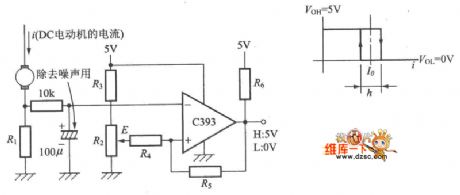
The DC motor-circuit detection circuit is as shown:
(View)
View full Circuit Diagram | Comments | Reading(664)
Detection and alarm circuit composed of the TWH9248 and TWH9249
Published:2011/5/12 8:14:00 Author:TaoXi | Keyword: Detection, alarm
The key components datathat will be used in this article: TWH9248 TWH9249
The TWH9248/TWH9249 is a pair of microwave sensing components (also known as the radar detector), and they can be used in the movement detection of the human body or object, the effective detection range is 3-6m, the operating voltage is 9-12V.
(View)
View full Circuit Diagram | Comments | Reading(605)
The level test circuit diagram composed of TTL NOR gate connecting as inverter
Published:2011/5/12 1:59:00 Author:Ecco | Keyword: level , test, TTL, NOR gate , connecting , inverter
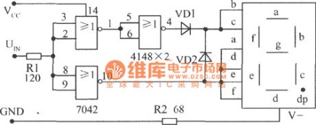
TTL NOR gate is connected as inverter, and it is equipped with common cathode LED,the high level shows q, low level displays 0. The circuit is shown in Fig.
The level test circuit diagram composed of TTL NOR gate connecting as inverter and matching common cathode LED (View)
View full Circuit Diagram | Comments | Reading(738)
OTIS TOEC-2000VF elevator maintenance circuit
Published:2011/5/12 19:50:00 Author:TaoXi | Keyword: OTIS, elevator maintenance circuit
OTIS TOEC-2000VF elevator maintenance circuit (View)
View full Circuit Diagram | Comments | Reading(644)
OTIS TOEC-40 elevator maintenance circuit
Published:2011/5/12 19:41:00 Author:TaoXi | Keyword: OTIS, elevator, maintenance circuit
OTIS TOEC-40 elevator maintenance circuit (View)
View full Circuit Diagram | Comments | Reading(715)
Infrared remote control detector
Published:2011/5/12 3:02:00 Author:TaoXi | Keyword: Infrared, remote control, detector
Infrared remote control detector (View)
View full Circuit Diagram | Comments | Reading(556)
RMS Power Measurement Circuit`
Published:2011/5/9 22:16:00 Author:Sharon | Keyword: RMS, Power Measurement
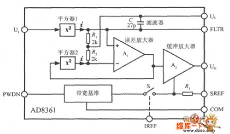
A true RMS power measurement circuit diagram is shown in below figure. The typical product corresponding to the circuit is the AD8361 monolithic RF RMS power detection IC. UI is for RF signal input, and Uo is for DC voltage output. Us termination is linked to+2.7 ~ +5.5 V power supply, and COM acts as public land. IREF is the work mode selective terminal, and PWDN is the sleep mode control terminal. FLTR is the filter terminal. Placing a capacitor between it and the Us side in parallel can reduce the filter cutoff frequency. SREF is the power control terminal. RF RMS voltage input from UI-end is UI, through square1 there generates a pulse current signal i proportional to UI2. The current signal gets through the square-law detector which is formed by the internal resistor R1 and capacitor C to obtain the mean square value of the voltage UI2, and then it is input to the error amplifier inverting.Squarer2 and the error amplifier can form a closed negative feedback circuit,whichwill addthe negative feedback signal into the error amplifier inverting input for temperature compensation. When the closed loop circuit reaches a steady state, the output voltage Uo (DC) is proportional to the input RMS power PIN. The relationship is: Uo = kPIN, where the k for the RMS / DC converter's output voltage sensitivity, AD8361 for k = 7.5mV/dBm.
This detection method has the following advantages: First, since the two squarers are identical, the change of range does not affect the conversion accuracy; second, when the ambient temperature changes, two squares can conduct mutual compensation, so that the output voltage is stable; third, the band of the used squarers are very wide, which isfrom DC to microwave frequencies.
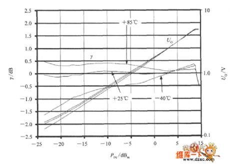
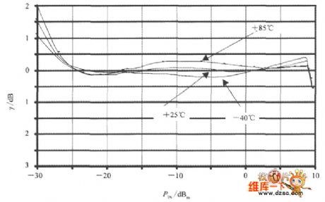
The RMS / DC detector Uo and PIN, γ the characteristic curve is shown below.
The figure shows that when input power is low, low temperature has a greater impact on output. AD8361 has internal temperature compensation circuit in itself. The characteristic curve after automatic compensation is shown below.
(View)
View full Circuit Diagram | Comments | Reading(1023)
Monolithic RF Power Measurement System AD8318 Typical Application Circuit
Published:2011/5/11 4:32:00 Author:Sharon | Keyword: Monolithic, RF power measurement, typical application
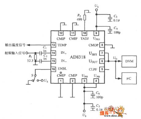
AD8318 typical application circuit is shown below. AD8318 is designed to measure RF power up to 8GHz. So, to maintain the insulation between the IN + and IN-pin and thefunctional unit circuit is essential. AD8318's positive power supply terminal UPSI and UPSO must take the same voltage. UPSI provides bias voltage for the input circuit andUPSO provides bias voltage for UOUT's low-noise output drive. Besides, there is still some independent public places within AD8318. CMOP is used as the public land of output drivers. All public places should be connected to PCB ground area of low impedance. The permitted supply voltage range is +4.5 ~ 5.5V. C3 ~ C6 is the power decoupling capacitors, which should be close to the power supply pin and ground. AD8318 applies AC coupled and single-ended input mode. When the input signal frequency is 1MHz ~ 8GHz, coupling capacitor (C1, c2) connected to the IN + and IN can use the 0402 1nF surface-mount-type ceramic capacitors, and coupling capacitors should be close to the IN +and IN-pin. External shunt resistor R1 (52.3Ω) is compatible with the IN + terminal, and can provide a 50Ω matching impedance of sufficient bandwidth. AD8318's output voltage can be directly sent to the digital voltmeter (DVM), and can also be sent to A / D converter's microcontroller (μC). To make AD8318 in working condition, ENBL end must be pulled through switch S to get a high electrical level(Us). When ENBL is grounded, AD8318 stays in sleep mode, and power supply current drops to 260μA. (View)
View full Circuit Diagram | Comments | Reading(984)
Monolithic RF Power Measurement System LT5504 Typical Application Circuit
Published:2011/5/11 4:30:00 Author:Sharon | Keyword: Monolithic, RF Power Measurement System, Typical Application
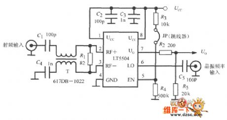
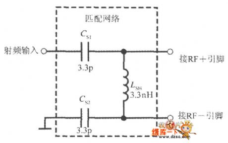
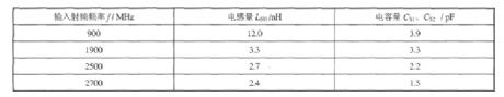

LT5504 typical application circuit is shown in the figure. RF signal passes through the coupling capacitor (C1) and 1:1 RF input transformer (T) to the LT5504 RF input. R1 is the shunt resistor. Crystal frequency is input to LO through terminal C5. Through the voltage divider R2 and R5, Uo end gets DC output voltage Uo. JP is the jumper. Since R4>> R3, when JP is connected, EN terminal raises the electrical level to make the circuit open. When JP is off,EN terminal drops the electrical level to close the circuit, and the chip gets into low power consumption mode. 1:1 RF input transformer's model number is 617DB-1022, which can also be replaced by the the narrow-band single-ended / differential conversion circuit constituted by three discrete components. The circuit is shownin the figureand the matching network's component values are listed in the table. According to different PCB design, the above-mentioned component values still need some adjustments.Voltage gain G of the narrow-band single-ended / differential conversion circuit is determined by below formula:
(View)
View full Circuit Diagram | Comments | Reading(759)
Monolithic RF Power Measurement System LTC5507 Typical Application Circuit
Published:2011/5/11 4:30:00 Author:Sharon | Keyword: Monolithic, RF Power Measurement, Typical Application
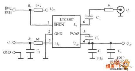
LTC5507 typical application circuit is shown in the figure. C1 is the RF input coupling capacitor, and C2 is the peak holding capacitor, both of which are ceramic capacitors and have less than 5Ω capacitance to reduce the ripple. C1 and C2's capacity depends on the minimum RF input frequency fmin (units of MHz), whose formula is: C1 = C21 ≥ (30fmin). Here, both C1 and C2's unit is μF. Considering the value of C2 will affect the conversion rate and bandwidth, generally C1 = C2. However, the capacity of C1 and C2 can not be set too big, otherwise it will exceed the minimum RF input frequency. Proper selection of the capacity of C1 and C2 can increase the conversion rate and the highest RF frequency AC characteristics. R3 is a pull-up resistor. When the SHDN is not floating, LTC5507 states in normal mode; when SHDN is grounded, LTC5507 turns to low-power consumption mode.
(View)
View full Circuit Diagram | Comments | Reading(1306)
Simplified circuit of the electricity measurement system (single-phase energy measurement system AD7751)
Published:2011/5/11 8:52:00 Author:Christina | Keyword: Simplified circuit, electricity measurement system, single-phase, energy measurement system
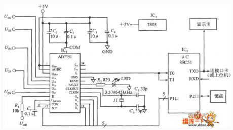
The simplified circuit of the electricity measurement system which is composed of the AD7751 and 89C51 singlechip is as shown in the figure. C1~C4 are the retreat coupling capacitance of the power supply. R connects to the VDD through the pull-up resistor (R=1), so the reset end failures. The crystal oscillator circuit is composed of the 3.579545MHz quartz crystal and the capacitors C5, C6, this crystal oscillator circuit supplies the clock to the AD7751. C7 is the de-noising capacitance of the UREF(I/O) end.
(View)
View full Circuit Diagram | Comments | Reading(1571)
high-accuracy monolithic data acquisition system ADuC824 single power supply circuit
Published:2011/5/11 7:56:00 Author:Christina | Keyword: high-accuracy, monolithic data, acquisition system, single power supply
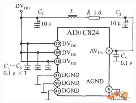
The high-accuracy monolithic data acquisition system ADuC824 single power supply circuit is as shown:
(View)
View full Circuit Diagram | Comments | Reading(553)
electricity testing pencil circuit
Published:2011/5/11 2:22:00 Author:Christina | Keyword: electricity, testing pencil
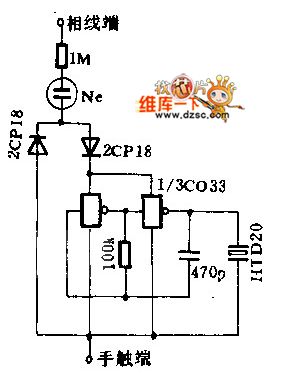
When you are testing the electricity, the weak current gets through the resistor and neon tube, and makes the neon tube toturn on, the current also makes the oscillation circuit (compose of the CMOS IC) to start oscillating, and makes the piezoelectric ceramic to send out voice.
(View)
View full Circuit Diagram | Comments | Reading(773)
RF Power Controller Circuit Formed by Monolithic RF Power Measurement System AD8318
Published:2011/5/10 2:22:00 Author:Sharon | Keyword: RF Power Controller, Monolithic, RF Power Measurement
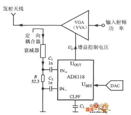
The working principle of the RF power controller is as shown. The control object can be a power amplifier(PA), variable gain amplifier (VGA), variable voltage attenuator (VVA) and so on. When selecting control mode, one should cut USET and UOUT pin from each other. The measured RF power signal is added to the AD8318's input through the directional coupler and attenuator. AD8318's set voltage comes from the D / A converter (DAC). The gain control voltage output from the AD8318's UOUT is used to control the output power of VGA (or VVA).
(View)
View full Circuit Diagram | Comments | Reading(817)
Night linear measuring benchmarking circuit
Published:2011/5/9 3:50:00 Author:Christina | Keyword: Night, linear measuring pole
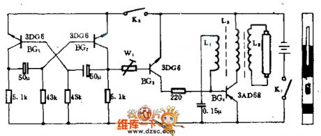
This benchmarking's night visual range is not less than 500m, with four 2-type batteries, this device can continuously works more than 30 hours, and it can be used in the night linear measurement applications or used as the signal marking equipment.
The interval oscillator is composed of the BG4 and L, this interval oscillator changes the 6V DC current into the 200V AC current and turns on the 3W cold cathode fluorescent tube as the night vision benchmarking's light source. The lamp tube can use three colors: red, white and green. BG3 is the switch tube, it is controlled by the oscillator to make the lamp tube produces flash. K2 is the work changing switch, if you need the lamp tube always turns on, you should cut off it.
(View)
View full Circuit Diagram | Comments | Reading(579)
Single-chip TRMS Power Measurement System AD8362 Demodulation Circuit
Published:2011/5/9 22:52:00 Author:Sharon | Keyword: Single-chip, TRMS, Power Measurement System, Demodulation
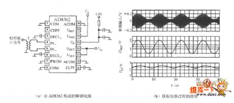
AD8362's UTGT side can constitute demodulation circuit. Take the envelope from the RF amplitude and restore it to the low and middle frequency signal before demodulation. The waveforms of the applied demodulation circuit and the process of obtaining envelope are shown in Figure (a), (b) below. It is assumed that the input signal is modulated 100kHz sine wave, and the carrier frequency is 100MHz. Link a voltage UT with an average of 1.25V, and 0.75V peak into the 14 feet, then the 12 feet's output voltage Uo is the 100kHz sine wave signal after its demodulation.
(View)
View full Circuit Diagram | Comments | Reading(1416)
Air Sensor Circuit Diagram
Published:2011/5/10 2:28:00 Author:Felicity | Keyword: Air Sensor Circuit Diagram,
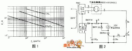
The resistance of some semiconductor decreases dramatically as the temperature increases in the atmosphere of some certain gas. And the performance of some material changes greatly while the gas concentration reaches a certain point. Thus this kind of semiconductor material including ferric oxide, tin oxide and zinc oxide could be made into air sensor. They will react under the atmosphere of methane, butane, ethanol or benzene.
Figure 1 shows the relation curve of the resistance of typical sensor R and the gas concentration P.
The air sensor ,type 8222 418 20031, is made according to this theory. It is consisted of a millimeter-size ceramic plate heating lamp and a electrode opposite to it. The work temperature is 300℃. It can work under both AC and DC condition. Figure 2 shows a simple air warning circuit. While the resistance of the 1kΩcontinuous potentiometer exceed a certain point, the thyristor will be turned on,and then the relay actuate to send a signal or make the actuator off. It is not until the stop button S is pressed that the relay is off again (View)
View full Circuit Diagram | Comments | Reading(672)
Typical application circuit of the single-phase electric power measurement system SM9903
Published:2011/5/10 19:08:00 Author:Christina | Keyword: Typical application, single-phase, electric power measurement
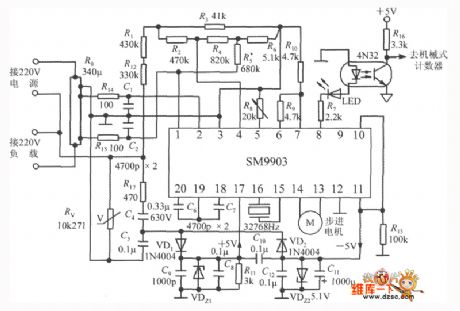
Typical application circuit of the single-phase electric power measurement system SM9903 is as shown. The constant of this watt-hour meter is 1600P/kWh, P corresponds to the 1kWh electricity output pulse, the basic measurement range is 5A, the maximum measurement range is 20A. The 220V alternating current gets through the 340μΩ manganese copper resistance R0 and changes into the current sampling signal, and this signal gets through the precision metal film resistor network and becomes the voltage sampling signal. The 220V alternating current uses the capacitance step-down method to supply power to the circuit, C4 is the step-down capacitance, VDz1 is the regulator tube of the +5V power supplier, VDz2 is the regulator tube of the -5V power supplier. Pin-8 outputs the active power integrated calculate pulse and this pulse is sent to the mechanical counter by optical coupler 4N32. The 32768Hz quartz crystals' frequency stability is 30X 10-6/oC, the equivalent inductance is 0.9mH, the load capacitance is 12.5pF, the equivalent resistance is 35 to 45kΩ. The C6, C7 are the integral capacitance. R8 uses the several-cycle fine-tune resistance. Rv is the 10K271 type thermistor that has the over-voltage protection function. LED is the red led.
(View)
View full Circuit Diagram | Comments | Reading(2506)
Lamp broken wire detection circuit diagram
Published:2011/5/9 21:06:00 Author:Nicole | Keyword: lamp, broken wire, detection
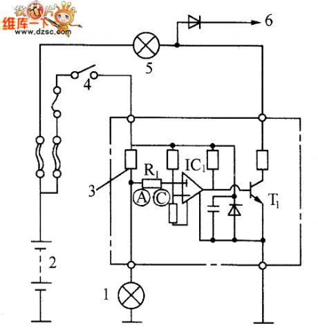
The lamp broken wire detection circuit is shown in the figure. The circuit internal has comparison amplifier IC1, it is a special integrated circuit for detecting broken wire, C point has reference voltage. In normal condition, current tests resistance R, this current should be larger than reference current, A point voltage is lower than reference voltage, the output of comparison amplifier IC1 is 0, transistor T cuts off, the alarm lamp is off.
When it is failure, the current on resistance R1 reduces, A point level rises and even higher than reference voltage, then the output of comparison amplifier IC1 is 1, the base of transistor T has current, T1 turns on, alarm lamp lights, it shows the circuit is failure.
(View)
View full Circuit Diagram | Comments | Reading(1371)
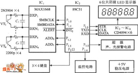
Multi-channel temperature recurring monitor system circuit diagram composed of MAX1668 and 89C51
Published:2011/5/10 3:20:00 Author:Nicole | Keyword: temperature, recurring monitor system
View full Circuit Diagram | Comments | Reading(1063)
| Pages:97/101 At 2081828384858687888990919293949596979899100Under 20 |
Circuit Categories
power supply circuit
Amplifier Circuit
Basic Circuit
LED and Light Circuit
Sensor Circuit
Signal Processing
Electrical Equipment Circuit
Control Circuit
Remote Control Circuit
A/D-D/A Converter Circuit
Audio Circuit
Measuring and Test Circuit
Communication Circuit
Computer-Related Circuit
555 Circuit
Automotive Circuit
Repairing Circuit