
Measuring and Test Circuit
Index 94
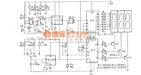
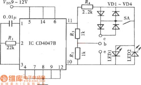
Quick Cardiotachometer Circuit Diagram
Published:2011/6/9 4:13:00 Author:Vicky | Keyword: Quick Cardiotachometer,
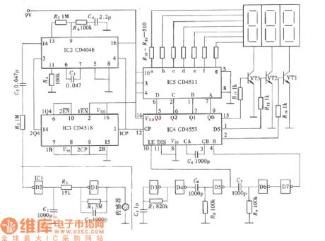
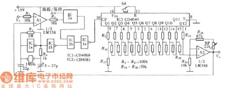
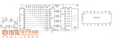
Cardiotachometer and frequency meter in fact belong to one sort of measure instrument. The difference is that the time gate of cardiotachometer is 1min, but not 1s. As to one measure instrument, measuring time of 1 min is long and hard to guarantee the precision. Therefore, alternate measuring is necessary, which meets the requirement of quickness and precision.The aboved picture is cardiotachometer circuit, and it can match the requirement of quickness and precision. (View)
View full Circuit Diagram | Comments | Reading(1809)
Digital Electronic Clock Calibrator Circuit Diagram
Published:2011/6/9 4:15:00 Author:Vicky | Keyword: Digital Electronic Clock Calibrator,
(View)
View full Circuit Diagram | Comments | Reading(1373)
Bicycle Speed Ometer Circuit Diagram
Published:2011/6/9 4:16:00 Author:Vicky | Keyword: Bicycle Speed Ometer,
Bicycle Speed Ometer (View)
View full Circuit Diagram | Comments | Reading(1146)
Typical Applied Circuit of LM1203 Integrated Circuit
Published:2011/6/9 4:16:00 Author:Vicky | Keyword: LM1203 Integrated Circuit,
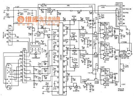
Typical applied circuit of video small-signal processing which is composed of LM1023 integrated circuit is shown as in the picture.
Hint: If the character is lack of color, the raster is white after make it brighter, and if the signal wire, input circuit and output circuit are normal under such circumstance, then generally speaking, this failure is caused by the damage of LM1203. (View)
View full Circuit Diagram | Comments | Reading(2257)
Analog Capacitance Admeasuring Device Circuit Diagram
Published:2011/6/9 4:23:00 Author:Vicky | Keyword: Analog Capacitance Admeasuring Device, CD4013
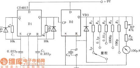
The picture is the circuit of analog capacitance admeasuring device. Use a double-D trigger, CD4013, and use one trigger of the double-Drigger, CD4013, together with a tested capacitance to constitute a monostable trigger to enable it to generate output pulse. The pulse width of this output pulse and the average current value is in proportion to the capacity of the tested capacitance. Use another one trigger of CD4013 to constitute a multivibrator to generate trigger pulse. A piece of IC can be used to constitute a simplified capacitance tester. The measurement range is l00pF~lμF. (View)
View full Circuit Diagram | Comments | Reading(1167)
Digital Frequency Meter Circuit Diagram
Published:2011/6/9 4:17:00 Author:Vicky | Keyword: Digital Frequency Meter,
(View)
View full Circuit Diagram | Comments | Reading(4549)
Capacitance Identification Device Circuit Diagram
Published:2011/6/9 4:22:00 Author:Vicky | Keyword: Capacitance Identification Device,
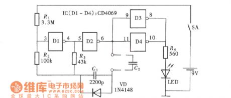
Capacitance identification device is not used to measure the capacity of the capacitor, but to identify whether the capacitor is good or bad, and whether it can be used, that is, whether there is short circuit or circuit break in the capacitor. It provides quality guarantee for making the circuit and reduce the unnecessary troubles. The circuit composition as is shown in the picture. This device can identify capacitors whose capacity are from 1pF to 1μF 1. (View)
View full Circuit Diagram | Comments | Reading(1028)
Electromagnetic Oscillation Demonstrator Circuit Diagram
Published:2011/6/9 4:26:00 Author:Vicky | Keyword: Electromagnetic Oscillation Demonstrator,
The picture is a circuit of electromagnetic oscillation demonstrator. It is displayed intuitively and visually in electromagnetic oscillation by the flow type pf luminous diode. The changing situation of galvanic current, magnetic field and electric field is also displayed in the procession of electromagnetic oscillation. Through coil current, it can display the change of circuit and magnetic field and the constitution of circuit, pulse drive circuit and work power supply.
(View)
View full Circuit Diagram | Comments | Reading(744)
Counter-type Peak Hold Circuit Diagram
Published:2011/6/9 4:06:00 Author:Vicky | Keyword: Counter-type Peak Hold,
(View)
View full Circuit Diagram | Comments | Reading(1063)
Electronic Tuner Circuit Diagram
Published:2011/6/9 4:04:00 Author:Vicky | Keyword: Electronic Tuner,
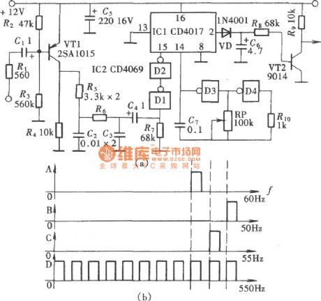
Tuner is a commonly seen standard sound calibrator. The tuning fork is usually made of metal. Beat it by hand to make it give out audio signal of 440Hz, and calibrate it by comparing with the calibrated sound. Electronic tuner is a sound calibrator made of electronic component. Electronic tuner is easier and more accurate than metal tuning fork, and what’s more, it can work continuously. The circuit principle is as shown in the picture. (View)
View full Circuit Diagram | Comments | Reading(958)
Infrared Sphygmograph Circuit Diagram
Published:2011/6/9 4:09:00 Author:Vicky | Keyword: Infrared Sphygmograph Circuit,
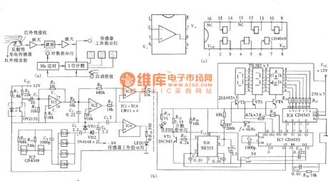
The so-called infrared sphygmograph means that the sensor that it uses to collect the signals is infrared sensor. Circuit is as shown in the picture. (View)
View full Circuit Diagram | Comments | Reading(772)
Field Frequency Identification Unit Circuit Diagram
Published:2011/6/9 4:20:00 Author:Vicky | Keyword: Field Frequency Identification Unit,
(View)
View full Circuit Diagram | Comments | Reading(606)
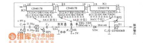
Three Digit Capacitance Circuit Diagram
Published:2011/6/9 4:29:00 Author:Vicky | Keyword: Three Digit Capacitance,
Three digit capacitance as shown in the picture is composed of basic pulse generator, gated circuit, control gate ,counter and decoding display.
The compositionand relation ofthe measuring range of every capacitancerating :
(View)
View full Circuit Diagram | Comments | Reading(969)
Bridge Rectifier Demonstrator Circuit Diagram
Published:2011/6/9 4:26:00 Author:Vicky | Keyword: Bridge Rectifier Demonstrator Circuit,
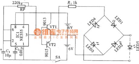
Bridge rectifier demonstrator circuit is a AC/DC conversion circuit. Bridge rectifier demonstrator circuit shown as in the picture reveals how the two groups of communication diode works in turn in the bridge rectifier circuit. It is made of pulse generator circuit, current direction control circuit, demonstrator circuit and power supply. (View)
View full Circuit Diagram | Comments | Reading(1329)
Arbitrary Number Pulse Circuit Diagram
Published:2011/6/9 3:53:00 Author:Vicky | Keyword: Arbitrary Number Pulse,
(View)
View full Circuit Diagram | Comments | Reading(590)
Digital Level Monitor Circuit Diagram
Published:2011/6/9 4:05:00 Author:Vicky | Keyword: Digital Level Monitor,
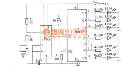
As is shown in the picture, digital level monitor can display the outgoing sound volume of sound amplifier by numbers. Because it adopts one digit display tube, the level it can display is from 1 to 9. (View)
View full Circuit Diagram | Comments | Reading(1047)
Sixteen Channels Digital Display Auto-patrol Circuit Diagram
Published:2011/6/9 4:08:00 Author:Vicky | Keyword: Sixteen Channels Digital Display Auto-patrol,
(View)
View full Circuit Diagram | Comments | Reading(643)
Ceramic Crystal Detector Circuit Diagram
Published:2011/6/9 4:08:00 Author:Vicky | Keyword: Ceramic Crystal Detector
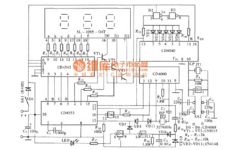
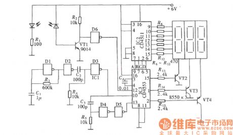
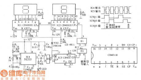
Ceramic crystal is crystal-type oscillator component used by infrared remote control launcher. The spoilage rate is comparatively high , and it is usually difficult to judge whether it is good or not in repairing. The detector as shown in the picture can quickly determine whether good or bad, which provides great convenience for repairing. The ceramic crystal detector actually is a three digit explicit frequency indicator, and the unit is KHz. (View)
View full Circuit Diagram | Comments | Reading(745)
Reaction Capability Tester Circuit Diagram
Published:2011/6/9 4:00:00 Author:Vicky | Keyword: Reaction Capability Tester, CD4017
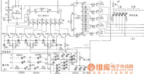
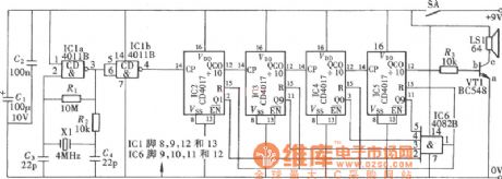
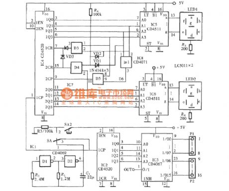
Reaction Capability Tester is used to test and train man’s quick-response capability. It has various type of construction and the Reaction Capability Tester as shown in the picture is composed of decimal counter CD4017 and luminous diode. The construction of Reaction Capability Tester is simple and can be used as a plaything to train and test children’s quick- response capability. (View)
View full Circuit Diagram | Comments | Reading(1541)
Transistor Online Detector Circuit Diagram
Published:2011/6/9 4:07:00 Author:Vicky | Keyword: Transistor Online Detector
Transistor online detector can test whether the transistor is good or bad without disassembling the transistor. Its working principle is as shown in the picture. This detector can not only be used to test the transistor independently, but also test the transistor online; not only test the PNP-type transistor, but also NPN-type transistor. It is of a relatively high practical value. (View)
View full Circuit Diagram | Comments | Reading(1365)
| Pages:94/101 At 2081828384858687888990919293949596979899100Under 20 |
Circuit Categories
power supply circuit
Amplifier Circuit
Basic Circuit
LED and Light Circuit
Sensor Circuit
Signal Processing
Electrical Equipment Circuit
Control Circuit
Remote Control Circuit
A/D-D/A Converter Circuit
Audio Circuit
Measuring and Test Circuit
Communication Circuit
Computer-Related Circuit
555 Circuit
Automotive Circuit
Repairing Circuit