
Measuring and Test Circuit
Index 99
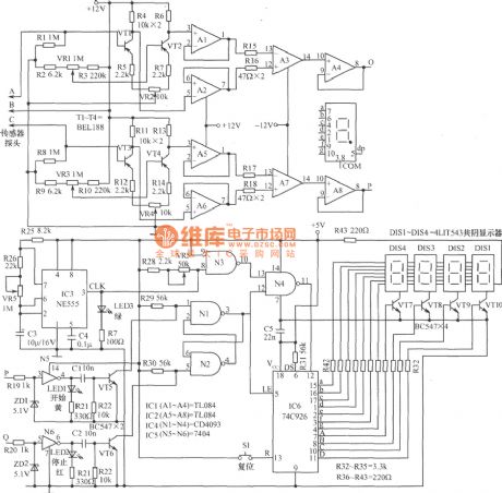
Bibulous rate measuring circuit diagram
Published:2011/4/28 21:37:00 Author:Ecco | Keyword: Bibulous rate , measuring
View full Circuit Diagram | Comments | Reading(899)
Measuring white brightness circuit diagram composed of LX1970 visible light sensor
Published:2011/4/28 2:17:00 Author:Ecco | Keyword: Measuring white brightness , visible light sensor
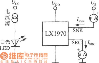
The chart shows the measuring white brightness circuit diagram composed of LX1970 visible light sensor. The visible light emitted by light source which is composed of UCC, white LED and current source and then visible light is received by the LX1970 and converted into current signal. In the SNK, SRC ends are connected with a microammeter in series, which are used to measure photocurrent ISNK, ISRC, microampere meter readings can reflect the level of brightness.
(View)
View full Circuit Diagram | Comments | Reading(628)
Circuit of Free Debug FM Transceiver composed of BA1404 and TDA7021
Published:2011/4/26 9:01:00 Author:TaoXi | Keyword: Free Debug, FM Transceiver
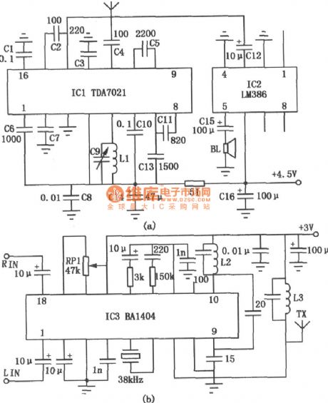
The most important features of this device are easy to make, it does not need to debug, especially this device does notneed the double-variable capacitor and intermediate frequency transformers, so it is very suitable tomake by the radio amateurs. Figure (a) is the receiving circuit; Figure (b) is the transmitter circuit.
When this circuit is transmitting the frequency of the signal 88 to 108MHz, the L2 use Φ0.65mm diameter enameled wire wound into 8mm, 10 turns of hollow coil. And the L3 use Φ0.6mm diameter enameled wire wound into 6mm, 8 turns of hollow coil.
(View)
View full Circuit Diagram | Comments | Reading(5347)
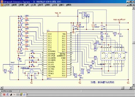
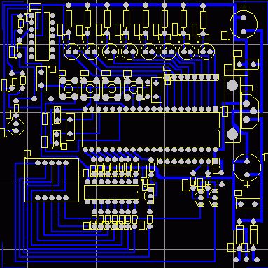
A professional 51 MCU test panel
Published:2011/4/26 3:51:00 Author:Ecco | Keyword: professional , MCU , test panel
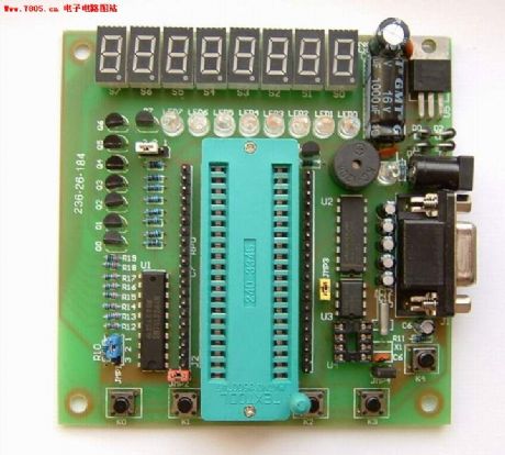
Onboard buzzer and reset button can be used to do some sound tests. Board four button inputs can be selectable interrupt / query. All four ports are connected to P can be pre-10K pull-up resistor row. IIC bus is connected real-time clock device PCF8563. IIC bus is connected to EEPROM device 24C02, the features are similar to the Hengjian's products. 74LS244 onboard driver chips can be driven by non-simple P port directly, it has better protection to single chip. MAX232 chip board ahs standard RS-232-C serial interface and it can be used for online testing for PC.
(View)
View full Circuit Diagram | Comments | Reading(1040)
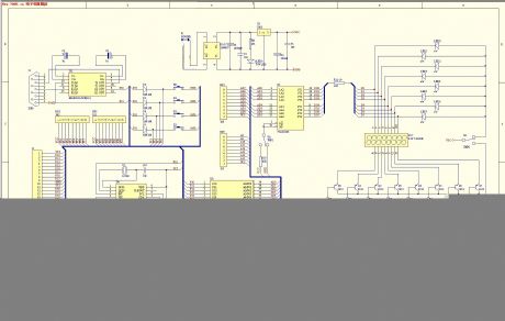
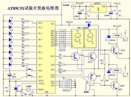
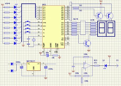
Microcontroller test board circuit 1
Published:2011/4/26 3:41:00 Author:Ecco | Keyword: Microcontroller, test board
The drawing is a more general test board circuit and suitable for ordinary and stones, gold and many other parts of the Treasure experimental procedure. Anyway, it has strong compatibility, versatility and usability. It can be used in water light, digital control, keyboard control, voice music, oscillator, etc.
(View)
View full Circuit Diagram | Comments | Reading(1540)
Phase detection circuit
Published:2011/4/25 22:55:00 Author:Nicole | Keyword: phase
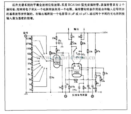
The blance full wave phase detector of IR spectrum system adopts RCA7360 light beam deflection tube, this deflection tube has 2 deflectors, it is used to transform the light beam from one electrode to another. The deflection tube switching action is controlled by reference waveform which is synchronous with input singal. Connecting a capacitor(8μF or 40μF) to output terminal, after charging with two and a half cycles, it will obtain a multiplication with the standard of input value. (View)
View full Circuit Diagram | Comments | Reading(1167)
Digital display pressure measuring circuit diagram
Published:2011/4/26 2:06:00 Author:Nicole | Keyword: digital display, pressure measuring

The figure (1) is a digital display pressure measuring circuit diagram. The performance of this circuit: the additional voltage is about 12.8V, the current is 30mA; when it is maximum gain, the input voltage range is 0.8mVW; the zero adjustment range is ±1mV/V; the shown value is 0-1999; the zero shift is 2μV/℃; the additional voltage shift is 0.005%℃; the nonlinear is ±0.05%FS; the noise peak-peak value is 1.5μV. LC filter is composed of L1、L2、C1 and C2, it is used to decrease the influence of electromagnetic noise.
(View)
View full Circuit Diagram | Comments | Reading(1329)
RF Modulator Circuit Composed of TA7673
Published:2011/4/23 22:46:00 Author:TaoXi | Keyword: RF Modulator
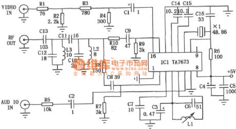
The RF modulator is the very important component in TV, VCR, satellite receiver, format converter, home computer and game machine. This circuit is simple, stable and easy to make, it can be easily connected with a lot kinds of circuit boards. The figure is the circuit of RF modulator, ICl is the modulator ASIC (TA7673), the 10-pin and 11-pin generate the image-carrier-frequency signal by external crystal oscillator, 4-pin and 5-pin generate the 6.5MHz second sound signal by external LC oscillation circuit. The ICl 6-pin bring in audio signal, and the ICl 16-pin bring in video signal, when the crystals with different operating frequency access to the IC1 (between 10-pin and 11-pin), this circuit will send out 1 to 5 channel's image-carrier-frequency signal between 2-pin and 15-pin. There is no need to debug the circuit, but the entire circuit should be shielded by a small metal box.
(View)
View full Circuit Diagram | Comments | Reading(7844)
MAX6303/MAX6302/MAX6301/MAX6304 Application Circuit
Published:2011/4/22 5:12:00 Author:Robert | Keyword: Application
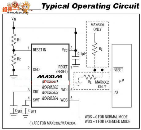
The MAX6303/MAX6302/MAX6301/MAX6304 application circuit is shown above. (View)
View full Circuit Diagram | Comments | Reading(876)
Small Irradiation Measure Circuit
Published:2011/4/24 9:08:00 Author:Christina
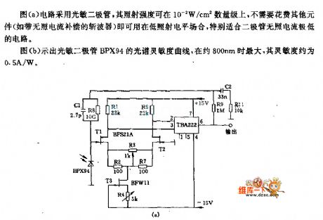
The circuit of figure (a) uses the photodiode, the irradiation intensity is about 0.01W/c㎡, there is no need to use the other devices such as the chopper without current compensation, so this circuit can be used in the low-level radiation conditions, particularly suitable for the low-level radiation diode circuit.
Figure (b) is the spectral sensitivity curve of photodiode BPX94, when the wavelength is about 800nm, the maximum sensitivity is about 0.5A/W.
(View)
View full Circuit Diagram | Comments | Reading(644)
Microcontroller test board circuit 2
Published:2011/4/25 1:51:00 Author:Ecco | Keyword: Microcontroller , test board
View full Circuit Diagram | Comments | Reading(947)
Microcontroller test board circuit 4
Published:2011/4/25 1:45:00 Author:Ecco | Keyword: Microcontroller , test board
View full Circuit Diagram | Comments | Reading(671)
Microcontroller test board circuit 3
Published:2011/4/25 1:45:00 Author:Ecco | Keyword: Microcontroller , test board
View full Circuit Diagram | Comments | Reading(1185)
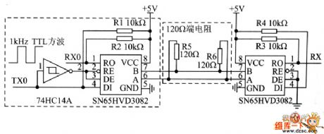
Automatic transceiver conversion RS-485 interface circuit and its test circuit diagram
Published:2011/4/24 22:25:00 Author:May | Keyword: Automatic transceiver conversion, RS-485, interface, test circuit
View full Circuit Diagram | Comments | Reading(813)
Cable test circuit
Published:2011/4/24 21:49:00 Author:Ecco | Keyword: Cable, test circuit
View full Circuit Diagram | Comments | Reading(1315)
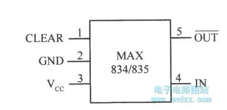
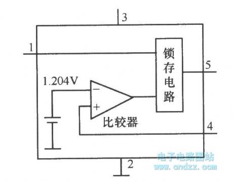
Micro-power voltage detection integrated chip MAX834/835 with latched output
Published:2011/4/21 4:31:00 Author:Nicole | Keyword: voltage detection, integrated chip, latched output
View full Circuit Diagram | Comments | Reading(670)
Circuit Of 555 Car Search Device
Published:2011/4/21 3:43:00 Author:TaoXi | Keyword: Car Search, Car Search Device, 555 Car Search Device
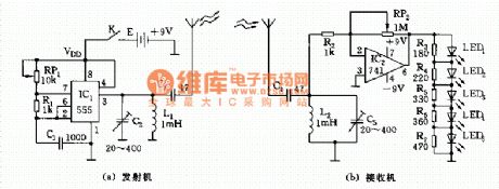
As shown, car search device composed of two parts, the transmitter and receiver. The transmitter is a medium wave frequency oscillaor with 555 as the core, the oscillator frequency should be selected lower than 535KHz, The value of frequency is decided by R1, RP1, C1 (F=1.44/(RP1+2R1)C1, L1, C2 form the output resonant circuit), then launch out by the antenna. Receiving circuit is composed of the input frequency selection network and the 741 op amplifier, magnification of the amplifier is decided by the ratio of RP2/R2. The LED1 ~ LED5 can be used to indicate the strength of the received signal, with the strengthening of the signal, LED will light one by one.
(View)
View full Circuit Diagram | Comments | Reading(1280)
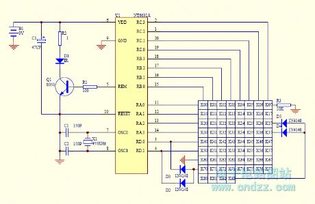
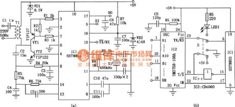
Schematic Of DF Data Transmission Module And Super-regenerative Receiver Module
Published:2011/4/20 21:59:00 Author:TaoXi | Keyword: DF Data Transmission Module, Super-regenerative Receiver Module
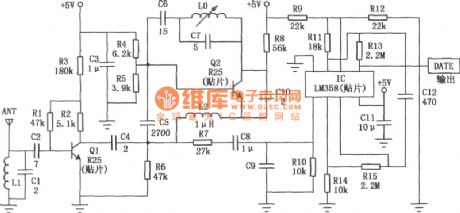
The operating frequency of the DF data transmission module is 315MHz, with the technology of surface acoustic wave resonator frequency stabilization, this module has great high frequency-stability. When the ambient temperature is between -25℃ to +85℃, the frequency drift is only 3×10⁻⁶ /℃, so this module is particularly suitable for multiple-transmit & single-receive wireless remote control and data transmission systems. Wireless data transmission technology is widely used in industrial data acquisition system, mini-wireless data terminal, vehicle monitoring, remote control, telemetry, access control systems, paging area, identification, RF contactless smart card, security, fire protection systems.
The equivalent circuit of the DF data transmission module:
DF receiver module circuit:
(View)
View full Circuit Diagram | Comments | Reading(5223)
Schematic of The Infrared Rays Wireless Headphone
Published:2011/4/20 4:06:00 Author:TaoXi | Keyword: Infrared Rays, Wireless Headphone
Because of the transmitter circuit of the inductive headphone must installed on the room wall or on the ceiling, so the inductive headphone can not be used outdoor, this is the main weak point of the inductive headphone. But the infrared rays wireless headphone is not in this case, for the flexible infrared rays transmitter circuit, it can be used in electronic teaching, home television and stereo equipment, audio wireless receiver, portable tape recorder, CD, VCD and MP3, makes the dream of wireless Walkman comes ture.
Figure (a) shows the transmitter circuit of the infrared rays wireless headphones. To use it, you need to put the plug XP into TV's or tape recorders's headphones socket. The audio signal coupled by the capacitive Cl, enlarged by the transistor VTl, and transmited the audio wave infrared rays by the infrared emitting diodes VDl and VD2. After installation, you need to adjust the bias resistor R2 to make the quiescent current is l0mA.
Figure (b) shows the receive circuit of the infrared rays wireless headphones. Infrared receiver VD3 ~ VD5 receive the infrared rays signal, converted it into audio signal, and enlarged by the transistor VT2 to bring in the integrated operational amplifier as power amplifier ICl, finally, the output signal exported by the headphone BE. To be able to receive signals all-round, there are three infrared rays receivers in the circuit. When testing, touch the positive electrode of the infrared rays receiver first, then adjust the resistor R4, R5 to make the Hum exported by the BE output largest, and then connect the transmitter circuit, adjusting the volume level of TV or radio cassette player, until the headset's outgoing volume become loud and clear.
(View)
View full Circuit Diagram | Comments | Reading(2948)
Power Line Communication Transceiver Circuit
Published:2011/4/20 6:25:00 Author:TaoXi | Keyword: Power Line Communication, Transceiver Circuit, LM567
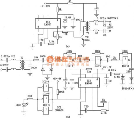
This electric circuit is the single-line power communication transceiver application circuit. It sends the analog and digital signals by 220V or 380V low-voltage power lines to complete wired communications. Figure (a) is the single-line power carrier transmission circuit, the core component IC1 is the audio PLL IC (LM567); Figure (b) is the single-line power carrier receiver circuit. (View)
View full Circuit Diagram | Comments | Reading(12088)
| Pages:99/101 At 2081828384858687888990919293949596979899100Under 20 |
Circuit Categories
power supply circuit
Amplifier Circuit
Basic Circuit
LED and Light Circuit
Sensor Circuit
Signal Processing
Electrical Equipment Circuit
Control Circuit
Remote Control Circuit
A/D-D/A Converter Circuit
Audio Circuit
Measuring and Test Circuit
Communication Circuit
Computer-Related Circuit
555 Circuit
Automotive Circuit
Repairing Circuit