
Measuring and Test Circuit
Index 89
Arbitrary Number System Counter Output Circuit Diagram
Published:2011/6/15 8:22:00 Author:Vicky | Keyword: Arbitrary Number System Counter ,

Output Circuit Diagram of Arbitrary Number System Counter (View)
View full Circuit Diagram | Comments | Reading(935)
Self Quality Detector Circuit Diagram
Published:2011/6/15 8:00:00 Author:Vicky | Keyword: Self Quality Detector
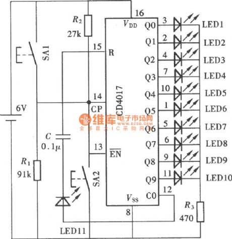
CD4017 is one of the most commonly used digital integrated circuits among all kinds of practical electronic circuits. The following is a simple Quality Detector and it can test the following details: first, whether the output performance of the ten output ends, Q0~Q9, is good or not; second, whether the input performance of clock pulse input end is good; third, whether the reset function of the reset terminal R works well; forth, whether the carry pulse output of the carry pulse output end CO works well. (View)
View full Circuit Diagram | Comments | Reading(918)
Intelligent humidity measuring instrument circuit composed of the HM1500/1520 humidity sensor and single-chip microcomputer
Published:2011/7/6 2:14:00 Author:Christina | Keyword: Intelligent, humidity measuring, instrument, humidity sensor, single-chip microcomputer
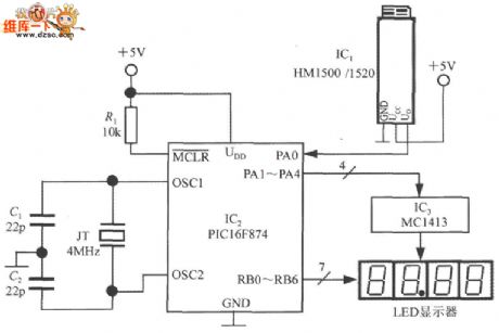
The intelligent humidity measuring instrument circuit which is composed of the HM1500/1520 humidity sensor and single-chip microcomputer is as shown in the figure. This instrument uses the +5V power supply, and has 4 common cathode LED digital tubes. This circuit uses three ICs: IC1 is the HM1500/1520 humidity sensor, IC2 is the 10-bit ADC single-chip microcomputer PIC16F874 which is produced by the United States Microchip company, IC3 is the 7 darlington invert driver array MC1413. The PIC16F874 is designed as one kind of cost-effective 8-bit SCM, it has the successive approximation type 10-bit A/D convertr, and it can convert 8 channels of humidity signal, now we only use one of the 8 channels.
(View)
View full Circuit Diagram | Comments | Reading(1467)
RF signal receiving strength indicator circuit composed of the MAX2015
Published:2011/7/6 2:34:00 Author:Christina | Keyword: RF signal, receiving, strength, indicator
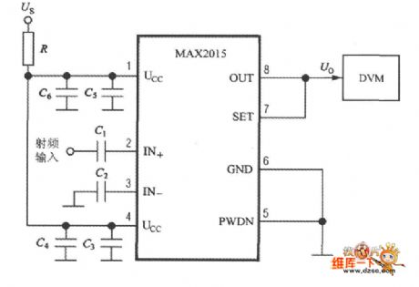
The RF signal receiving strength indicator circuit which is composed of the MAX2015 is as shown in the figure. The RF signal is connected with the IN+ port through the coupling capacitance C1, the IN- port is connected with the ground through the coupling capacitance C2. The internal 50Ω resistances of the IN+ and IN- ports can be matched with the 50MHz~3.0GHz RF circuit. The capacities of C1 and C2 are 680 pF. The C3 and C4 are the power-supply decoupling capacitance. If you short connect the OUT port with the SET port, the MAX2015 will be in the detection mode. The output voltage Vo of the OUT port adds to the digital voltmeter to display the strength of the receiving RF signal.
(View)
View full Circuit Diagram | Comments | Reading(1067)
Intelligent pressure measurement and control instrument circuit
Published:2011/7/6 2:18:00 Author:Christina | Keyword: Intelligent, pressure, measurement, control, instrument
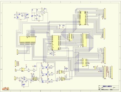
Intelligent pressure measurement and control instrument circuit is as shown in the figure:
(View)
View full Circuit Diagram | Comments | Reading(689)
Simple telephone repair instrument circuit
Published:2011/7/6 2:43:00 Author:Christina | Keyword: Simple, telephone, repair instrument
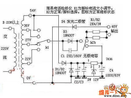
The Simple telephone repair instrument circuit is as shown in the figure:
(View)
View full Circuit Diagram | Comments | Reading(1152)
Line-Output Transformer Short-Circuit Detection Circuit Diagram
Published:2011/7/4 10:06:00 Author:Vicky | Keyword: Line-OutputTransformer, Short-Circuit Detection
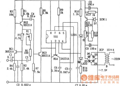
As part of the line-output transformer short-cut detection circuit, dropout pulse is composed of 555, BG4, C6, and R9 etc. When the transformer works normally, the timing cycle of monostable timing circuit which is made of 555, R9 and C6 is longer than the cycle of input trigger pulse. Therefore, under continuous triggering, pin 3 of 555 presents high level (about +5V) continuously, luminous diode LED2 (green) is lighted to the line-out transformer works well without short circuit or punch-through. If there is short circuit of punch-through, then because of mutual-inductor among the transformer windings, the transformer presents low impedance, high-damping, and the oscillator stops working. The correspondent 555 gives out low level through pin ③ for pin ② cannot receive trigger signal. Then the luminous diode LED1 (red) is lightened to indicate the abnormality of the transformer. (View)
View full Circuit Diagram | Comments | Reading(1789)
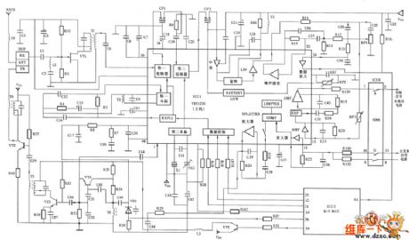
The host RF circuit of Telsda HW838 (4) P/ISD—LED wireless telephone
Published:2011/6/23 0:33:00 Author:qqtang | Keyword: RF circuit, wireless telephone
View full Circuit Diagram | Comments | Reading(961)
The wireless emitter microphone circuit--high sensitivity microphone circuit production
Published:2011/6/24 8:01:00 Author:qqtang | Keyword: wireless, emitter microphone, high sensitivity
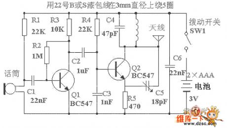
The circuit is simple and cheap, whose output power is not higher than 5-8mV, the emitting range is about 300m in citizen area, the signal is received with a FM radio, which indicates its good sensitivity and clearance, the most challenging part of designing the circuit is making a 3V power supply and a half-wave aerial have this emitting capability. Besides, as the circuit needs few elements, so the circuit can be put in a match box (which is a little bigger than the local match box) as the wiretap.
(View)
View full Circuit Diagram | Comments | Reading(1906)
The Detection and alarm circuit composed of the TWH9248 and TWH9249
Published:2011/6/14 2:47:00 Author:TaoXi | Keyword: Detection, alarm
The key components datathat will be used in this article: TWH9248 TWH9249
The TWH9248/TWH9249 is a pair of microwave sensing components (also known as the radar detector), and they can be used in the movement detection of the human body or object, the effective detection range is 3-6m, the operating voltage is 9-12V.
(View)
View full Circuit Diagram | Comments | Reading(577)
Circuit Diagram of Multiplication Detector Composed of MC1496
Published:2011/7/2 0:01:00 Author:Vicky | Keyword: Multiplication Detector
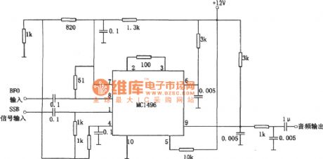
The above picture is a multiplication detector circuit. The circuit is single side band amplitude-modulated signal detection. Its demodulation principle is to complete demodulation by multiplying the received SSB Signal and transmitting carrier wave which is recovered by the receiving end. Integrated module MC1496 in the picture is a balanced modulator and demodulator, and the output voltage of the circuit is the product of input voltage signal and switch function. When the circuit works in an intermediate frequency of 9MHz, the sensitivity is 3μV, and the dynamic range is 90dB. (View)
View full Circuit Diagram | Comments | Reading(2551)
Monolithic liquid crystal display range finder circuit composed of the intelligent ultrasonic ranging integrated circuit 4Y4
Published:2011/7/5 21:22:00 Author:Christina | Keyword: Monolithic, liquid crystal display, range finder, intelligent, ultrasonic, ranging integrated circuit
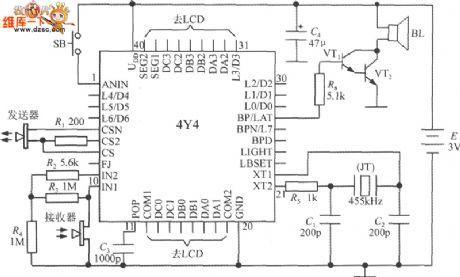
The monolithic liquid crystal display range finder circuit which is composed of the intelligent ultrasonic ranging integrated circuit 4Y4 is as shown in the figure. The meter is composed of the ultrasonic transmitter, the receiver, the LCD displayer, the button switch and the buzzer (or the speaker), in order to simplify the lead, we directly weld the 4Y4 at the back of the LCD display board. The pin-2 ~ pin-4, pin-8, pin-23 ~ pin-26 and pin-28 ~ pin-30 are not needed. R1 is the current-limiting resistance of the transmission circuit. R2~R4 are the external components of the receiving amplifier.
C3 is the automatic reset capacitance. The crystal oscillator circuit uses the low-cost 455kHz piezoelectric ceramic to instead of the quartz crystal (JT), C1 and C2 are the oscillation capacitance. SB is the button switch.
(View)
View full Circuit Diagram | Comments | Reading(1514)
Logarithmic detection power law circuit
Published:2011/7/4 7:15:00 Author:John | Keyword: detection power law
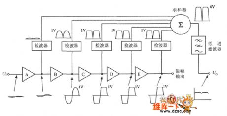
Logarithmic detector is composed of multi-stage logarithmic amplifiers and its circuit is as shown. A total of five logarithmic amplifiers (A ~ E) are shown in the figure. Gain of each logarithmic amplifier is 20dB (that is five times more of the voltage amplification factor). Its maximum output voltage is limited to 1V. Therefore, the slope value of the logarithmic amplifier is ks = 1V/20dB = 50mV/dB. The output voltage of five pairs of logarithmic amplifier is sent to the summing device (Σ) after respectively though the detector. At the end, the voltage is passing through the low-pass filter to output the voltage Uo. (View)
View full Circuit Diagram | Comments | Reading(895)
single-chip True RMS power measured system AD8362 true RMS level measuring meter circuit
Published:2011/7/4 10:53:00 Author:John | Keyword: single-chip True RMS, power measured system, true RMS level measuring device
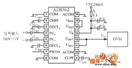
AD8362 True RMS level measuring meter circuit is as shown. The AD8362's output voltage is directly sent to the digital voltmeter (DVM). It should be noted that it belongs to the voltage level meter because the DVM reading is proportional to the measured rms voltage’s logarithm. And the meter’s display unit is dBv. During the measurement for high frequency RF input signal, the following measures should be taken: one is to increase the input decoupling capacitor (or RC decoupling network) and the other is to minimize the length of input signal lead, decoupling capacitors lead and ground wire.
(View)
View full Circuit Diagram | Comments | Reading(2468)
monolithic true RMS power measurement system AD8362 input protection circuit
Published:2011/7/4 10:45:00 Author:John | Keyword: monolithic true RMS, power measurement system, input protection
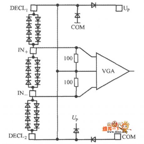
AD8362 input protection circuit is as shown. Two anti-pole composite diodes are set between the IN + and IN- in parallel, which can play a role of being with clamping protection. It also can avoid input of the sensor to damage the chip due to the instantaneous high voltage. Besides, the diode clamp protection circuit is designed to be placed in the pine between the DECL1 and IN +, IN- and the DECL2.
(View)
View full Circuit Diagram | Comments | Reading(713)
Simplied Cable Quick Test (74HC4017) Circuit Diagram
Published:2011/6/26 0:53:00 Author:Vicky | Keyword: Simplied Cable Quick Test
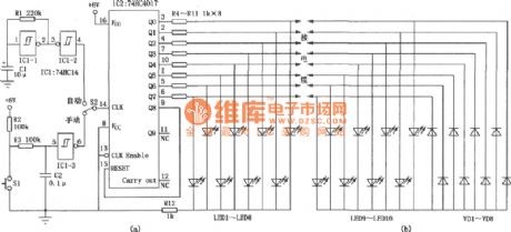
Cable Quick Test is mainly used to test the on-off situation of regional computer network cable and the analogous comprehensive digital cable and analog cable. It is much easier and quicker than multimeter. The circuit is divided into main circuit and remote circuit, so it can still be used to test even if the two ends of the cable are in different places. The main circuit constitutes a clock generating circuit which is composed of IC1 invert Schmidt trigger 74HC14 and a luminous diode LED sequent-lighting circuit which is compose of IC2. It is shown in picture(a). The roment circuit is shown in picuture (b). (View)
View full Circuit Diagram | Comments | Reading(2777)
Circuit Diagram of Frequency-Coversion Electromagnetic Dotting Timer composed of CD4017
Published:2011/6/26 0:52:00 Author:Vicky | Keyword: Frequency-Coversion Electromagnetic Dotting Timer
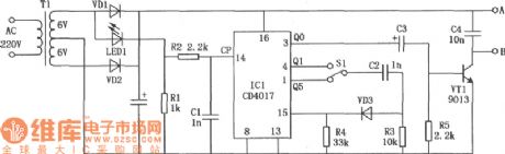
The main defection of electromagnetic dotting timer is the big shortfall. The reasons are: first, the needle of the electromagnetic dotting timer will cause rubbing effect to the recording paper when dotting and therefore make the moving speed of the paper slow down; second, the electromagnetic is driven by the AC whose voltage has been reduced, and time interval of the dotting is a cycle of alternative current, that is 0.02s.
The above circuit as shown in the picture adds a frequency-conversion power by making use of electronic crossover technique on the base of J0203-1 dotting timer commonly-used in senior schools so that the needle of J0203-1 dotting timer can timing with different cycles. (View)
View full Circuit Diagram | Comments | Reading(816)
Inductive Electricity Test Pencil (CD 4069) Circuit Diagram
Published:2011/6/23 8:41:00 Author:Vicky | Keyword: Inductive Electricity Test Pencil
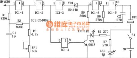
IC1 is a hex inverter integrated circuit CD4069 and its inverter IC1-1 together with surrounding components constitutes a high input impendent and high gain voltage amplifier. The probe receives the weak electric field signal, sends it out after amplified by amplifier and
Control the post-stage circuit via inverter IC1-2. Inverters IC1-5, IC-6, resistance R5 and capacitance C2 constitute the multivibrator, whose work is controlled by the working state of inverter ICl-3. When the probe detects signal, IC1-3 sends out high level, the diode VDI ends, and oscillator works and make the piezoelectric ceramics HTD give out sounds. Meanwhile inverter IC1-4 sends out high level, triode VTI is conducted, red luminous diode LED2 lightens which represents the guide line under test is electrified. (View)
View full Circuit Diagram | Comments | Reading(3283)
Resistance Quick Tester Diagram Circuit
Published:2011/6/16 10:52:00 Author:Vicky | Keyword: Resistance Quick Tester
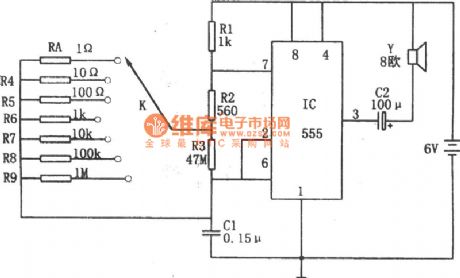
The above picture is the Quick Resistance Tester Diagram Circuit. The core of the circuit is multivibrator composed of 555, R1, R2, R3, Rx (resistance under test) and C1. Resistances numbered from R4 to R9 are known resistance of the tester.
A circle of the multivibrator output signal is T=0.693[R1+2(R2+R3Rx/(R3+Rx))].The frequency of the multivibrator can be changed when the position of gating switch K is changed, and thus signal of different tones is given out from the speaker. Because the resistance values of resistances numbered from R4 to R9 are known and Rx is a to-be-tested resistance, it is easy and quick to estimate the range og resistance value of the resistance under test by comparing with the loudness level of the know resistances’ corresponding oscillator frequency.
(View)
View full Circuit Diagram | Comments | Reading(752)
Light metering stationery case light metering circuit
Published:2011/7/4 1:01:00 Author:Christina | Keyword: Light metering, stationery case, light metering circuit
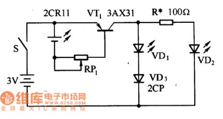
The light metering circuit of the light metering stationery case is as shown in the figure. This circuit uses the 2CRll silicon photocell as the light metering component, and this 2CRll silicon photocell is installed on the surface of the stationery case to feel the light intensity. The VD1 and VD2 are two light-emitting diodes that can be used to indicate the strength of the light. When the illumination is less than 10Olx, the voltage which is produced by the silicon photocell is small, the VT1's tube voltage is large or it is in the cut-off state, the two light-emitting diodes VD1 and VD2 will not turn on; when the illumination is between 100-20Olx, the voltage that is produced by the silicon photocell will increases, the voltage drop of VT1 reduces, the light-emitting diode VD2 turns on, this means the illumination is moderate.
(View)
View full Circuit Diagram | Comments | Reading(615)
| Pages:89/101 At 2081828384858687888990919293949596979899100Under 20 |
Circuit Categories
power supply circuit
Amplifier Circuit
Basic Circuit
LED and Light Circuit
Sensor Circuit
Signal Processing
Electrical Equipment Circuit
Control Circuit
Remote Control Circuit
A/D-D/A Converter Circuit
Audio Circuit
Measuring and Test Circuit
Communication Circuit
Computer-Related Circuit
555 Circuit
Automotive Circuit
Repairing Circuit