
Index 237
Optical control automatic rice distribution machine circuit
Published:2011/4/29 22:25:00 Author:Nicole | Keyword: optical control, rice distribution machine
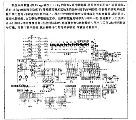
According to the quantity of purchased rice, such as 15kg, you can push 15kg button, to make the tractive magnet which controls the counter poise move, then the 15kg counter poise automatically falling; according to the kinds of japonica rice or indica rice, to push kinds button, it can control the food-importing port of japonica rice or indica rice gate open, then the rice flow to the funnel of platform scale. Fixing source bulb and light-sensive diode in the vane of platform scale, ater it is amplified, the relay will take action to drive tractive magnet work. When it is nearly the wanted quantity, the steelyard will close the food-importing port, the rice is added from the small gate; then the steelyard rises slowly, when it reaches the standard, the light source is cut off, relay closes the small gate, the standard singal light on. To push the released rice button, the electromagnet of platform scale's delivery gate pulls up, then the rice will flow into haversack. (View)
View full Circuit Diagram | Comments | Reading(674)
Opto-electrical range acquisition circuit
Published:2011/4/24 5:05:00 Author:Nicole | Keyword: opto-electrical range acquisition circuit
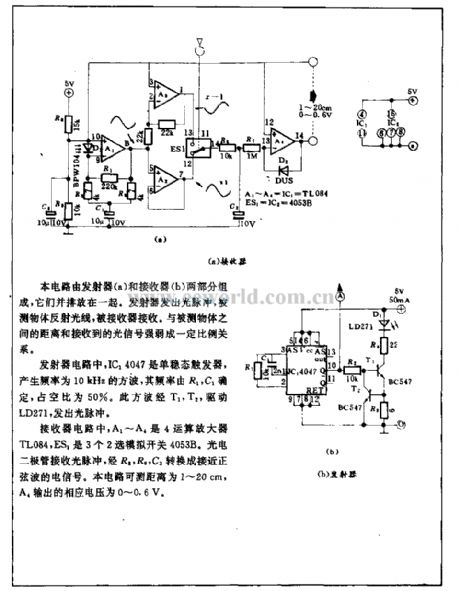
This circuit is composed of transmitter(a) and receiver(2), they are put side by side. Transmitter emits optical pulse, the light is reflected by the measured object and then received by the receiver. It has proportional relationship to the distance of measured object and the degree of received optical singal.
In transmitter circuit, IC14047 is monostable trigger, it produces 10kHz square wave, the frequency is decided by R1, C1, the duty ratio is 50%. By T1, T2, this square wave drives LD271 to emit optical pulse. (View)
View full Circuit Diagram | Comments | Reading(661)
Opto-electrical adjustment circuit
Published:2011/4/22 21:36:00 Author:Nicole | Keyword: opto-electrical adjustment circuit
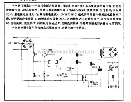
This circuit can be used to adjust a high voltage power supply. Indicator light #327 is connected to the output terminal of high voltage rectifier, its brightness changes in relation to output voltage. When the output voltage of high voltage rectifier is too high, the brightness of indicator light increases, the resistance of phototube Q3 reduces, Q1 collector current increases, Q2 collector current decreases, the frequency of unijunction transistor oscillation circuit composed of 2N4870 and C1 drops, limited by the frequency response of pulse transformer T1, MAC14 grid can not reach the trigger level, when the AC singal is zero passage, the light turns off automatically. The primary current of transformer T2 is reduced by R1 branch, then the output voltage of high voltage rectifier drops.
The feature of this circuit is to isolate the regulator from the dangerous high voltage. (View)
View full Circuit Diagram | Comments | Reading(660)
Regulated power supply circuit diagram used VMOS as switching element
Published:2011/4/8 2:38:00 Author:Nicole | Keyword: regulated power supply, switching element
As shown, it is a power supply circuit used VMOS as switching element. VT5 is VMOS power transistor, the switch adjustment element of power supply; L1is the energy storage inductor; VD3 for the freewheeling diode; VT3 for the FET, as the constant current source of VTl, VT2, to provide the emitter with lmA constant current; Cl is the input filter capacitor; C5, C6, C7 is the output filter capacitor.
It is determined by the relative voltage of the two base to turn on VTl or VT2 first. If the base potential of VT1 below VT2, the VTl on, VT2 off; on the contrary, the VTl off, VT2 on. The base potential of VT2 is decided by resistances R2, R3 and voltage regulator diode VD1, it is a constant; and base potential of VTl is obtained from the output voltage through the resistor R6C R, and derived from the potentiometer R8, the output voltage can be changed by adjusting potentiometer R8.
In order to reduce the power consumption of switch regulator VT5, to improve its turning speed, the circuit adopts bootstrap network which composed of R5, C4. When VT5 is off, the source potential is 0V, the input voltage charge to C4 through diode VD2 resistor R4, so that the voltage on C4 is close to the input voltage. When VT5 is on, the source potential rise, as there is sufficient voltage on the capacitor C4, so that the diode VD2 off, by this time, the voltage on R5 is close to 2 times the input voltage, so VT5 turn on more quickly. At this point even if the input voltage is low, the circuit also can be flipped. The role of C2, C3 is to make VT1, VT2 flip quickly, then to improve the speed of switching.
(View)
View full Circuit Diagram | Comments | Reading(1439)
Separately excited switching power supply circuit diagram using single-junction transistor as pulse generator
Published:2011/4/27 9:06:00 Author:Nicole | Keyword: switching power supply, single-junction transistor, pulse generator
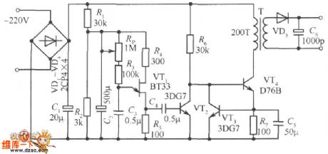
In figure: VD1 ~ VD4 and C1 is rectifying filter circuit, turning 220V AC network voltage into 300V DC voltage. Pulse generator consists of an unijunction transistor VT1, resistors R3, R4, R5, potentiometer RP and capacitor C3, to change the potentiometer's resistance can lead to the changing of pulse frequency. C4 is the coupling capacitor of output pulse. Rl and R2 divide 300V DC voltage to unijunction transistor VT1 and provide 20 ~ 30V operating voltage. VT2 is the inversion amplifier tube, it can invert and amplify the positive pulse outputed by pulse generator, transporting a negative pulse to switch VT4, so that it is ended when VT1 outputs positive pulse. (View)
View full Circuit Diagram | Comments | Reading(3340)
Pulse width modulated switching power supply circuit with stabilized voltage
Published:2011/4/27 9:05:00 Author:Nicole | Keyword: switching power supply, pulse width modulated
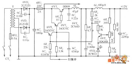
As shown, the main technical indicators are as follows: Output voltage: 12V; Output Current: 1A; power consumption <20W; efficiency> 64%; internal resistance <0.075Ω; ripple <15mV; mains voltage: 160 ~ 240V. Inthe figure, full-wave rectifier circuit is composed of 6VDl, 6VD2; 6C3 is the filter capacitor; 6C1, 6C2 areused to undermine the surge current; self-excited multivibrator is composed of 6VT1, 6VT2, 6VT3 and 6R4, 6C9, and the 6VT1 also is the switching tube. When the 12V output voltage decreases for some reason, the base of the error amplification 6VT4 obtained the voltage from the sampling circuit 6R6, 6R11, 6R8 also will be dropped, the collector voltage of 6VT4 rose, the potential base of 6VT3 also increased, the output pulse of the switch adjustment 6VT1 broadened, then the reduced voltage rising again. On the contrary, when the output voltage drops, it will make a reverse adjustment according to the aboveprocess, then keeping the output voltage steady.
(View)
View full Circuit Diagram | Comments | Reading(2482)
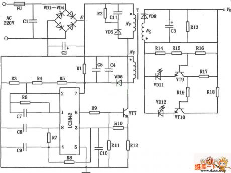
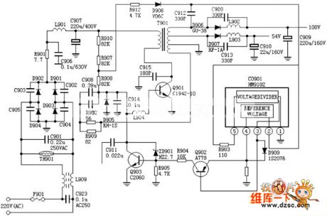
electric bicycle battery charger UC3842 circuit diagram
Published:2011/5/4 9:34:00 Author:Nancy | Keyword: electric bicycle, battery charger
View full Circuit Diagram | Comments | Reading(5502)
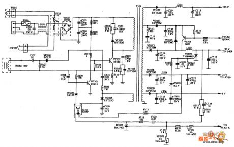
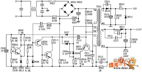
WYSE VGA-670 display power supply circuit diagram
Published:2011/5/4 9:52:00 Author:Nancy | Keyword: WYSE, display, power supply
View full Circuit Diagram | Comments | Reading(812)
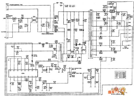
VOLTRON V-1501 display power supply circuit diagram
Published:2011/5/4 9:54:00 Author:Nancy | Keyword: VOLTRON, display, power supply
View full Circuit Diagram | Comments | Reading(876)
VGA V-1415 display power supply circuit diagram
Published:2011/5/4 9:55:00 Author:Nancy | Keyword: VGA , display, power supply
View full Circuit Diagram | Comments | Reading(1313)
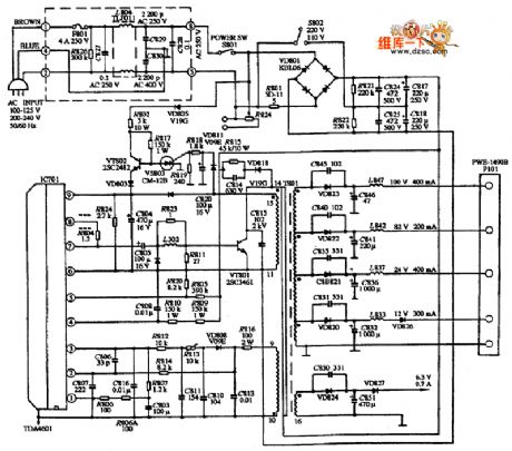
PWB-1509 color display power supply circuit diagram
Published:2011/5/4 10:14:00 Author:Nancy | Keyword: color display , power supply
View full Circuit Diagram | Comments | Reading(794)
PMV-P-14VC display power supply circuit diagram
Published:2011/5/4 10:17:00 Author:Nancy | Keyword: display, power supply
View full Circuit Diagram | Comments | Reading(720)
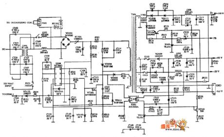
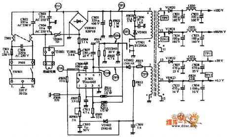
TDA4605 thick film switching power supply IC diagram
Published:2011/5/4 2:11:00 Author:Ecco | Keyword: thick film, switching power supply, IC
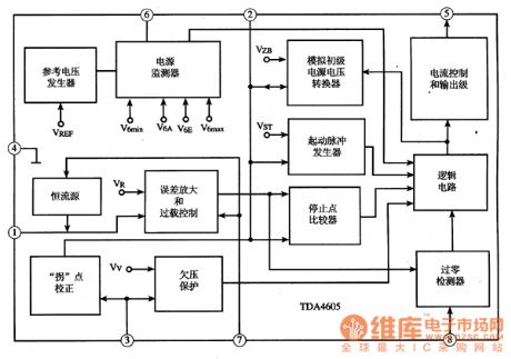
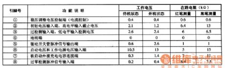
TDA4605 thick film switching power supply IC diagram is produced by Philips, which is widely used in domestic and imported large screen color TV and color display. TDA4605 integrated circuit includes voltage regulator sampling processing circuit, under voltage protection detection circuit, the excitation pulse output circuit, soft start control circuit, its internal circuit diagram shown in Figure 1 million. The 8-pin IC-style packaging million, the pin functions and data listed in Table 1. Figure 1 TDA4605 integrated circuit within the circuit block diagram
Table 1 showsTDA4605 integrated circuit pin functions and data
(View)
View full Circuit Diagram | Comments | Reading(1294)
LED zero-beat indicating circuit
Published:2011/4/13 4:08:00 Author:Nicole | Keyword: LED, zero-beat indicating
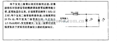
Two LEDs are connected with opposite polarity, it depends on the receiver accurate tune to the emission signal to display the zero-beat frequency conveniently and intuitively. When deviate beyond zero-beat frequency1kHz, two LEDs are conduction all the time; when deviate in zero-beat frequency 20Hz, two LEDs are flashing; when beat is in ±5Hz, LEDs are extinction. The luminous intensity of LED is determined by low-frequency response of the adopted audio amplifier. (View)
View full Circuit Diagram | Comments | Reading(525)
Single power supply change into dual power supply circuit
Published:2011/5/3 6:19:00 Author:Christina | Keyword: Single power supply, dual power supply
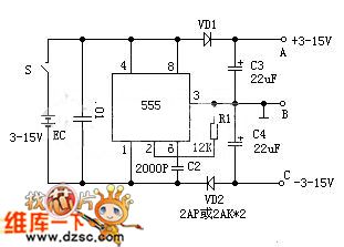
In the circuit, time base circuit 555 connected as an astable circuit (pin-3's output frequency is 20 KHz, duty cycle is 1:1). When the pin-3 is high level voltage, C4 is charged by the electric current; when the pin-3 is low level voltage, C3 is charged by the electric current. Because of the presence of VD1, VD2, the C3, C4 can be charged by the current, but can not be discharged, the maximum charge value is EC, if you connect the B to ground, you will get the +/-EC dual power at both ends of A, C. This circuit's output current is more than 50 mA.
(View)
View full Circuit Diagram | Comments | Reading(2680)
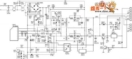
SANYO 83P Switching Power Supply Circuit
Published:2011/5/3 6:56:00 Author:Felicity | Keyword: SANYO Switching Power Supply Circuit,

The picture above shows the SANYO 83P Switching Power Supply Circuit. (View)
View full Circuit Diagram | Comments | Reading(1314)
SANYO 80P Switching Power Supply Circuit
Published:2011/5/3 6:44:00 Author:Felicity | Keyword: SANYO Switching Power Supply Circuit,
The picture above shows the SANYO 80P Switching Power Supply Circuit. (View)
View full Circuit Diagram | Comments | Reading(1638)
Hitachi Circuit of NP8C Switching Power
Published:2011/5/3 6:33:00 Author:Felicity | Keyword: Hitachi Circuit of Switching Power,
The picture above shows the Hitachi Circuit of NP8C Switching Power. (View)
View full Circuit Diagram | Comments | Reading(892)
Hitachi A1PM8C Switching Power Supply Circuit
Published:2011/5/3 6:27:00 Author:Felicity | Keyword: Hitachi Switching Power Supply Circuit,
The picture above shows the Hitchi A1PM8C Swotching Power Supply Circuit. (View)
View full Circuit Diagram | Comments | Reading(933)
Schematic of Flash Circuit Design
Published:2011/5/3 5:26:00 Author:Felicity | Keyword: Schematic of Flash Circuit Design,
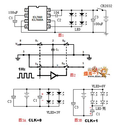
The picture above shows the Schematic of Flash Circuit Design. (View)
View full Circuit Diagram | Comments | Reading(1482)
| Pages:237/291 At 20221222223224225226227228229230231232233234235236237238239240Under 20 |
Circuit Categories
power supply circuit
Amplifier Circuit
Basic Circuit
LED and Light Circuit
Sensor Circuit
Signal Processing
Electrical Equipment Circuit
Control Circuit
Remote Control Circuit
A/D-D/A Converter Circuit
Audio Circuit
Measuring and Test Circuit
Communication Circuit
Computer-Related Circuit
555 Circuit
Automotive Circuit
Repairing Circuit