
Function Signal Generator
Index
Telephone electronic coded lock circuit
Published:2011/7/27 8:27:00 Author:Fiona | Keyword: electronic coded lock

Telephone electronic coded lock circuit is shown as above,the electronic coded lock is suitable for double audio circuits.After the phone adds this coded lock, when you call out,you must use the buttons on the phone to press the four pre-programmed password,then you can make a call.If the password is error, the phone can not dial out. When the exterior line is incoming call,the phone can receive the ring signal normally,picking machine can response.When the electronic coded lock circuitis connected toexterior line to be used,we mustmeasure the positive and negative polarities of outside feeder,then connect the positive pole to L1 and connect L2 to the negative pole,the phone is connected to the the phone location in electronic coded lock circuit.
(View)
View full Circuit Diagram | Comments | Reading(1775)
Telephone and facsimile apparatus protection circuit
Published:2011/7/11 2:51:00 Author:Fiona | Keyword: Telephone and facsimile apparatus, protection
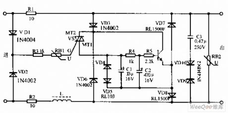
Telephone and facsimile apparatus protection circuit is shown as above,due to the exterior line often appears instantaneous high voltage to result in the damage of the telephone,the facsimile apparatus and so on.In view of this situation,this protection circuit can effectively prevent the damage of the telephone and the facsimile apparatus because of lightning stroke and line's accidental over-voltage.The circuit has no affect on telephone and facsimile apparatus completely. The transistor VD is 9013 and β = 65-115;Directional triode thyristor VS is SAC616;Resistor is the RJ type,nominal power is 0.25 ~ 0.5W on average.
(View)
View full Circuit Diagram | Comments | Reading(750)
Internal telephone circuit
Published:2011/7/1 5:53:00 Author:Fiona | Keyword: Internal telephone
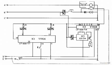
Internal telephone circuit is shown as below,improving slightly a toy telephone will become a variable practical internal telephone. This phone is compose of the phone component,decoding circuit,ringing circuit and other components. Using more than two the same device parameters telephone connected by wire can constitute internal telephone.
(View)
View full Circuit Diagram | Comments | Reading(2316)
The crossbar user extension outside metering device circuit
Published:2011/7/7 7:22:00 Author:Fiona | Keyword: The crossbar user, extension outside metering device
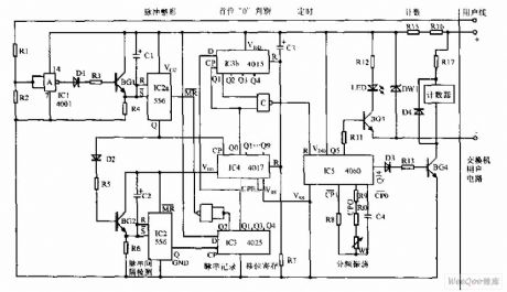
The crossbar user extension outside metering device circuit is shown as above,this device is suitable for HJ-905, HJ-906-type extension outside metering device that the the crossbar user switchboard. The metering device has a easy circuit, low cost and easy maintenance features.As the counting device is for each extension units,for convenience of copy times,it equips with 4-digit electromagnetic counter,it's eye-catching visual. The metering device is composed of pulse shaping,pulse string of gap detection, the first 0 discrimination, pulse string of records, timing and counting circuit and other circuit.
(View)
View full Circuit Diagram | Comments | Reading(1066)
series attenuation test circuit
Published:2011/7/8 4:13:00 Author:Fiona | Keyword: attenuation test
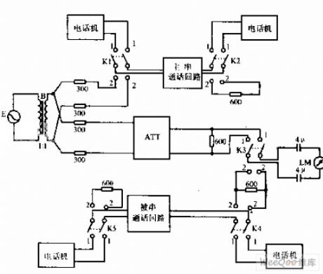
Compared with the transmission attenuation measurement circuit,series attenuation test circuit adds two pole-throw switch K4,K5.
(View)
View full Circuit Diagram | Comments | Reading(807)
Telephone anti-theft trick lock circuit
Published:2011/7/8 10:36:00 Author:Fiona | Keyword: anti-theft trick lock
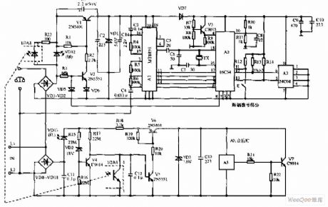
Telephone anti-theft trick lock circuit is shown as above, this lock's specific functions as follows: 1.1~4 any limited prefix numbers, such as 0 , 173 , 9688 , can lock 1000 groups. 2.4 * password,confidentiality is strong.3.it can change the password and limited number at any time.4.* it delays about 6S to automatically shut after call to prevent free call on limited number. 5 Setting the password and limited number are operated on telephone.6.When the outside line is parallel operation theft,it makes a alarm sound to disturb the theft phone, while the red light is bright.7.The green light is bright when the users calling,it says the line is busy. Circuit is divided into limited local dial-up and parallel operation thief dozen two completely independent parts.
(View)
View full Circuit Diagram | Comments | Reading(779)
Telephone electronic ringer circuit
Published:2011/7/8 11:24:00 Author:Fiona | Keyword: electronic ringer
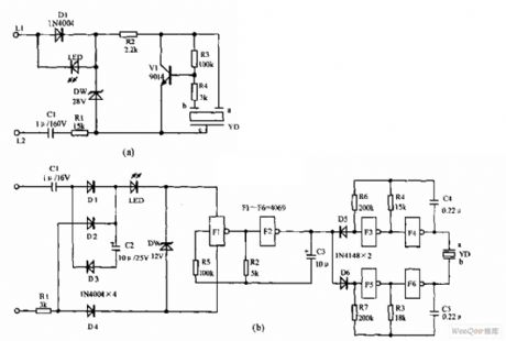
Telephone electronic ringer circuit is shown as above,Figure (a) is the electronic ring circuit with an NPN transistor V1 (choose 9014 or 3DG12) as the core, sound devices YD is also feedback devices composed of the feedback pole and the buzzer equipped with the help of the sound chamber. L1, L2 connect to circuit line;C1 and R1 have limiting and reducting voltage effects; R2 is the isolation resistor.D1 is the commutation diode.DW is the clamper tube. Figure (b) is the electronic ringing circuit with A general CMOS integrated block CD4069(or 4069, MC4069, TC4069)as the core design.
(View)
View full Circuit Diagram | Comments | Reading(2637)
Telephone diacritical transponder circuit
Published:2011/7/9 2:55:00 Author:Fiona | Keyword: diacritical transponder
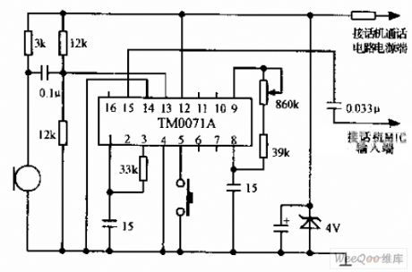
Telephone diacritical transponder circuit is shown as above,the diacritical transponder increases diacritical speaker function for the telephone and keeps secret for identity of the person who answers the phone.Diacritical integrated circuit TM0071A (or KTS00T1A) is New single piece of large-scale speech processing integrated circuit and dual in-line 16-pin package,the voltage range is 3 ~ 5V, the power supply can be obtained after the telephone power supply maintains the voltage.When installing,it removes the transmitter MIC of theoriginal telephone,connects the MIC input terminal of the output connection phone and power supply side to telephone power supply,all components can be mounted on a small circuit board.The circuit board can be put in the phone's leisure place.Function conversion can use a micro switch which is fixed on the phone shell.
(View)
View full Circuit Diagram | Comments | Reading(933)
Telphone convenient lamp circuit
Published:2011/7/9 2:31:00 Author:Fiona | Keyword: convenient lamp
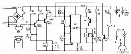
Telephone convenient lamp circuit is shown as above,S is the tact switch connected with microphone key,it is off at ordinary times, it is connected in off-hook status.HA is piezoelectric ceramic chip which is pasted in the speaker YD,L1 and L2 are the telephone lines.When it has no ringing signal or it isn't in off-hook state,3 terminal of NE555 is low potential,relay J does not work,and when it has a ringing signal or it is in off-hook state, J is conducted to make K close and H light.it is thus clear that the convenient lamp provides timely lighting when you receive and make a call at night.
(View)
View full Circuit Diagram | Comments | Reading(625)
Phone number coded lock circuit
Published:2011/7/9 0:38:00 Author:Fiona | Keyword: number coded lock
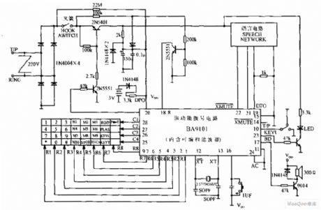
Phone number coded lock circuit is shown as above,this picture is the specific application circuit of digital password integrated blocks BA9101,it is composed of keyboard,multi-functional dial-up integrated network circuit,peripheral control circuit and so on.This coded lock has a major, minor secondary control,it is suitable for three kinds of use levels and can respectively control according parameters.Keeping password and parameters is supplied by the lithium battery,it is not lost in five years.
(View)
View full Circuit Diagram | Comments | Reading(1111)
Telephone hands-free circuit
Published:2011/7/9 0:23:00 Author:Fiona | Keyword: hands-free
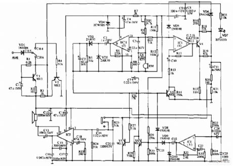
Telephone hands-free circuit is shown as above, this picture is HA22 (VI) P/TD type telephone hands-free circuit produced by jiangsu.When the telephone is in h-f state,the receiver is replaced by speaker; The microphone is replaced by sound power converter(the pickup) BM. hands-free circuit is composed of IC1, IC2 six transistor (9013) and so on. When the switch CH5 and CH6 are linked together,hands-free indicator VD7 is bright, the telephone enters into the h-f state, when CH5,CH4 are linked together or off-hook, the hands-free circuit is closed.
(View)
View full Circuit Diagram | Comments | Reading(2251)
The releasing interfere and preventing thief dozen circuit
Published:2011/6/30 3:19:00 Author:Fiona | Keyword: The releasing interfere, preventing thief dozen
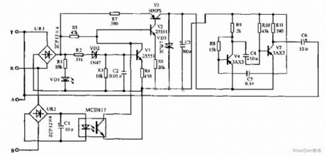
The releasing interfere and preventing thief dozen circuit is shown as below,T,R is the phone into the line side,telephone is connected to the A, B-side.When the user uses the telephone,the burglar alarm does not work. When a theft or fight occurs, the line voltage reduces,transistor V1 is cut-off, base V2 obtains the high potential to be conducted,V3 is conducted too,so that there is output voltage on the stabilivolt VD3,the oscillator has electricity,the oscillator has electricity through the C6 input,the C6 output oscillation voltage to the telephone line,disturbs the pirates caller.
(View)
View full Circuit Diagram | Comments | Reading(665)
Hands-free telephone terminal circuit
Published:2011/6/29 1:49:00 Author:Fiona | Keyword: Hands-free telephone terminal
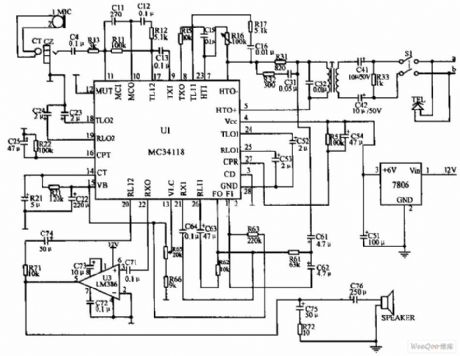
Conference call terminal is made by the hands-free phone chips, high-quality hands-free phone chips MC34118 ensure the properties of the machines is reliable,elements connected way and the parameter selection of the part pins in the circuit components in the connection and parameters chose retaining the original MC34118 basic connection,however,it makes some change at microphone input, speaker output,power supply and telephone line connection to meet the needs to listen to teleconference.
(View)
View full Circuit Diagram | Comments | Reading(4103)
Voltage Control Function Generator Circuit of μA709
Published:2011/6/25 21:45:00 Author:Michel | Keyword: Voltage Control, Function Generator, Circuit
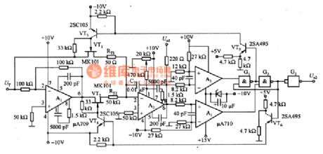
The picture 6-50 is the voltage control function generator circuit of μA709.In the circuit,A1 is charge reversal circuit,VT1~VT4 are analog switches,A2 is mueller integral circui,A3 and A4 are PWL comparing circuit,VT6,VT5 and G1-G3 are trigger circuit.VT1 and VT2 analog switches control voltgae UT to control the operational amplifier A1, integrating circuit's intergration composed of timing resistance RT (RT1 and RT2) and the forms of A2 output linear rising and fall.If VT1 conducts,A2 output linear declines because positive step voltgae intergrates. (View)
View full Circuit Diagram | Comments | Reading(2163)
pic16c54 control Gree electronic sterilizer circuit
Published:2011/6/4 13:29:00 Author:John | Keyword: electronic sterilizer
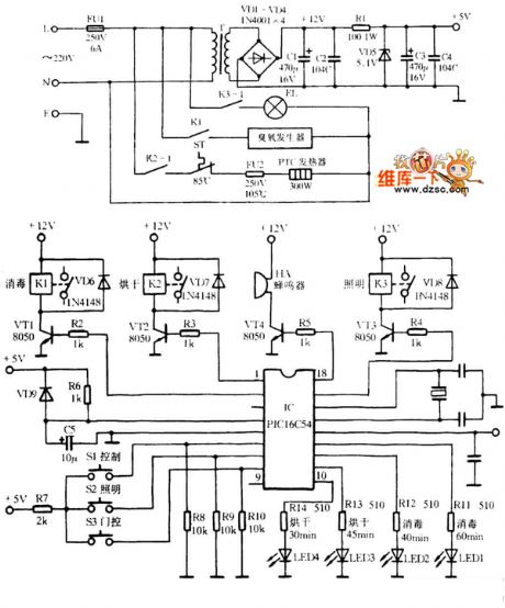
pic16c54 control Gree electronic sterilizer circuit is shown in the following.
(View)
View full Circuit Diagram | Comments | Reading(1824)
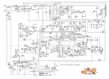
HF-10A type electromagnetic cooker circuit
Published:2011/6/5 22:12:00 Author:John | Keyword: electromagnetic cooker
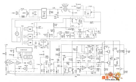
HF-10A type electromagnetic cooker circuit is shown in the following.
(View)
View full Circuit Diagram | Comments | Reading(965)
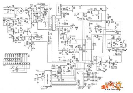
Yonghua M0-88 type electromagnetic cooker circuit
Published:2011/6/5 22:08:00 Author:John | Keyword: electromagnetic cooker
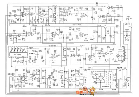
Yonghua M0-88 type electromagnetic cooker circuit is shown below.
(View)
View full Circuit Diagram | Comments | Reading(756)
Wanbao DC2-13 series type electromagnetic cooker circuit
Published:2011/6/5 10:45:00 Author:John | Keyword: electromagnetic cooker
Wanbao DC2-13 series type electromagnetic cooker circuit is shown in the following.
(View)
View full Circuit Diagram | Comments | Reading(1061)
Suopu SP-200 type cooker circuit
Published:2011/6/5 10:20:00 Author:John | Keyword: cooker
Suopu SP-200 type cooker circuit is shown below.
(View)
View full Circuit Diagram | Comments | Reading(880)
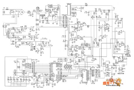
Fujitsu computer-style electromagnetic cooker circuit (1H ~ 1000H (700 ~ 1300W)
Published:2011/6/6 0:38:00 Author:John | Keyword: electromagnetic cooker
Fujitsu computer-style electromagnetic cooker circuit (1H ~ 1000H (700 ~ 1300W) is shown in the following.
(View)
View full Circuit Diagram | Comments | Reading(829)
| Pages:1/2 12 |
Circuit Categories
power supply circuit
Amplifier Circuit
Basic Circuit
LED and Light Circuit
Sensor Circuit
Signal Processing
Electrical Equipment Circuit
Control Circuit
Remote Control Circuit
A/D-D/A Converter Circuit
Audio Circuit
Measuring and Test Circuit
Communication Circuit
Computer-Related Circuit
555 Circuit
Automotive Circuit
Repairing Circuit