
Sine Signal Generating
Index 2
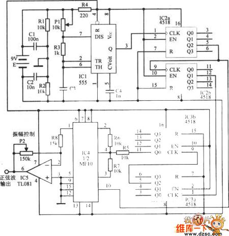
SIMPLE_SINE_WAVE_GENERATOR
Published:2009/6/18 21:49:00 Author:May
A 555 timer operating in the astable mode generates the driving pulses and two 4518 dual BCD (binary coded decimal) counters provide the square waves. A TL081 op amp serves as an output buffer-amplifier, and potentiometers R1 and R2 are used in order to control the pulse's frequency and amplitude, respectively.The output-frequency range can be varied by changing CX. For example, a value of 0.1 μF gives a range from about 0.1 to 30 Hz, and avalue of 470 pF gives a range from about 10 Hz to 1.5 kHz. The maxirttum output frequency is 30 kHz. (View)
View full Circuit Diagram | Comments | Reading(2343)
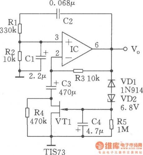
1_Hz_SINE_WAVE_OSCILLATOR
Published:2009/6/18 21:46:00 Author:May
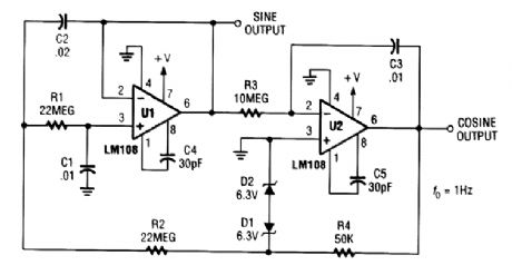
This circuit produces a 1-Hz sine wave using two op amps. A single-chip dual op amp could be used as well. (View)
View full Circuit Diagram | Comments | Reading(1304)
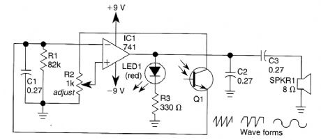
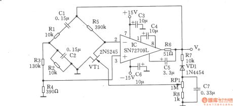
BATTERY_POWERED_SINE_WAVE_GENERATOR
Published:2009/6/18 21:45:00 Author:May
The quality of the sine wave depends on how closely you match the components in the twin-T network in the op amp's feedback loop. (View)
View full Circuit Diagram | Comments | Reading(1168)
Vienna bridge sinusoidal oscillator circuit
Published:2011/7/17 1:26:00 Author:Fiona | Keyword: sinusoidal oscillator
View full Circuit Diagram | Comments | Reading(1061)
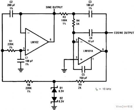
High frequency sine wave generator and orthogonal output circuit
Published:2011/7/17 1:23:00 Author:Fiona | Keyword: High frequency, sine wave generator, orthogonal output
View full Circuit Diagram | Comments | Reading(3688)
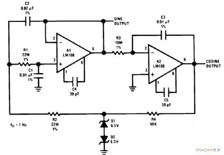
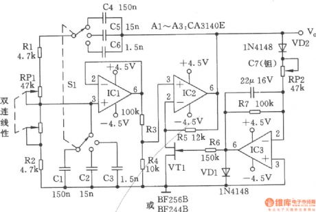
Low frequency sine wave generator and orthogonal output circuit
Published:2011/7/17 1:22:00 Author:Fiona | Keyword: Low frequency, sine wave generator, orthogonal output
View full Circuit Diagram | Comments | Reading(3572)
Waveform generator made by single chip
Published:2011/7/10 23:26:00 Author:leo | Keyword: Waveform generator, single chip
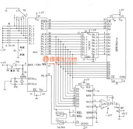
As the picture shows, it is a waveform generator made by MCS-51 single chip. It has the features of simple circuit, compact construction and low price. It can produce triangle waveform, sawtooth waveform, sine waveform, square waveform and others. These six kinds of waveform can be connected to each other and constant cyclically output or be one of them can be selected out to output constantly. If key controller and LED displayer are set to it, the square wave output frequency can be set and shown by changing the software. (View)
View full Circuit Diagram | Comments | Reading(860)
RC sine wave oscillator circuit
Published:2011/6/9 21:17:00 Author:John | Keyword: sine wave oscillator
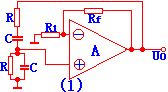


Common RC sine wave oscillator circuit is RC series-parallel sine wave oscillator circuit. It is also called Wien bridge sine wave oscillator circuit.
Series-parallel network here is regarded as an option for frequency and feedback network. The circuit is just shown in Figure (1):
Its starting condition is and its oscillation frequency is .It is mainly used for low-frequency oscillations. To generate a higher frequency sinusoidal signal, the LC sine wave oscillator circuit is generally adopted. Its oscillation frequency is . Quartz oscillator is characterized by its particularly stable oscillation frequency, so it is commonly used in occasions with highly stable oscillation frequency.
(View)
View full Circuit Diagram | Comments | Reading(691)
Sine Wave Generator Circuit
Published:2011/5/17 1:44:00 Author:Robert | Keyword: Sine Wave, Generator
The Sine Wave Generator Circuit is shown below.
(View)
View full Circuit Diagram | Comments | Reading(853)
Quartz crystal sinusoidal oscillator
Published:2011/4/25 4:46:00 Author:Ecco | Keyword: Quartz crystal, sinusoidal oscillator
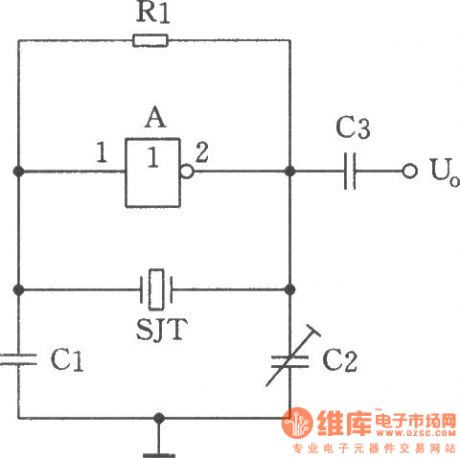
The circuit shown as the chart is a sine wave oscillator which is composed of the quartz crystal resonator SJT and one gate of six inverter IC CD4069. And comparing with ordinary RC phase shift oscillator, the crystal oscillator's frequency stability can be up to 0.00001 or higher. This is the high targets which RC phase-shift oscillator can not achieve (RC phase shift oscillator frequency stability can only reach the order of 0.01). CMOS NAND gate and negative feedback bias resistor Rl form the inverting amplifier. Quartz crystal SJT and Cl, C2 constitute a 7c positive feedback subcircuit. When quartz crystal is in the vicinity of its natural resonance frequency, it is self-inductive, the inductors and capacitors Cl, C2 constitute a resonant circuit, the forming selective frequency phase shift feedback network is back to the amplifier input to produce oscillation. Adjusting the capacitor C2 can fine-tune the oscillation frequency. Components Selection: Six inverter manifold A: CD4069. Capacitor Cl: 20pF, C2: 3 ~ 22pF, C3: 1000pF. Resistor Rl: 10MΩ. Crystal SJT: 32.768kHz. Circuit connection method: six integrated circuit CD4069 inverter only uses 1 / 6 door, the remaining doors can be used to connect to its input termination VDD or VSS when no other uses, the output is floating. (View)
View full Circuit Diagram | Comments | Reading(1332)
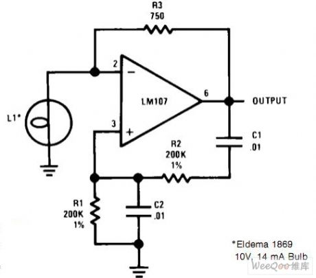
Stable sine wave oscillator composed of F007
Published:2011/4/21 6:39:00 Author:Ecco | Keyword: Stable sine wave oscillator
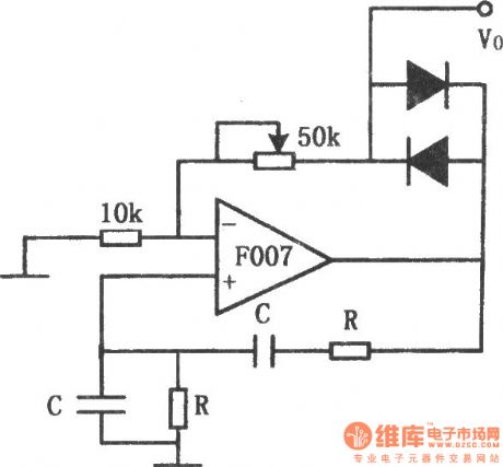
The chart shows the stable sine wave oscillator circuit. In order to obtain a stable oscillation, it requires a loop gain with 1. If the gain is too large, the waveform will occur distortion; if the gain is too small, the circuit will stop vibration. This circuit uses two diodes to stabilize the oscillation. When the output voltage is too low, the diode cuts off, negative feedback is cut off, the loop gain to improve the output voltage increased. When the output reaches a certain value, the diode conduction, the loop gain is improved, output voltage increases. And when the output rate reaches a certain value. The potentiometer in the figure is used to adjust the output amplitude and distortion. The oscillation frequency of the circuit is decided by the resistor R and capacitor C: f0 = 1/2πRC.
(View)
View full Circuit Diagram | Comments | Reading(861)
The double-T sinusoidal oscillator with stable output composed of LM170
Published:2011/4/20 21:48:00 Author:Ecco | Keyword: double-T, sinusoidal oscillator , stable output

The chart shows the double-T sinusoidal oscillator circuit with stable output. The circuit uses the automatic gain control amplifier LM170 to stabilize its amplitude. This approach can guarantee the waveform distortion. Even if the double-T loop and the amplifier gain changes, it can ensure the output amplitude constant. Component values can compensate for 40dB changes. 100k potentiometer is used to change the threshold level of automatic gain control, thereby changing the output level. Circuit oscillation frequency: f0 = 1/2π, RC uses the value of the marked components in the figure, the oscillation frequency is approximately 1kHz.
(View)
View full Circuit Diagram | Comments | Reading(1673)
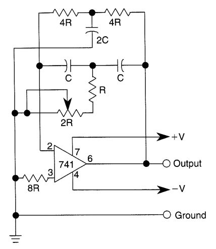
RC sine-wave generator composed of LM741CN
Published:2011/4/20 21:40:00 Author:Ecco | Keyword: RC , sine-wave generator
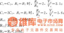
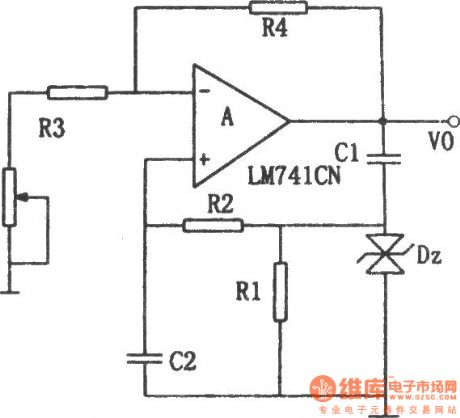
The chart shows the RC sine-wave generator. The components can be selected according to the following formula:
(View)
View full Circuit Diagram | Comments | Reading(2327)
Wien-bridge sine wave generator 1
Published:2011/4/10 22:42:00 Author:Ecco | Keyword: Wien-bridge , sine wave generator
View full Circuit Diagram | Comments | Reading(752)
Wien-bridge sine wave generator 2
Published:2011/4/10 22:43:00 Author:Ecco | Keyword: Wien-bridge , sine wave generator
View full Circuit Diagram | Comments | Reading(631)
Wien-bridge sine wave generator 3
Published:2011/4/10 22:45:00 Author:Ecco | Keyword: Wien-bridge, sine wave generator
View full Circuit Diagram | Comments | Reading(1268)
| Pages:2/2 12 |
Circuit Categories
power supply circuit
Amplifier Circuit
Basic Circuit
LED and Light Circuit
Sensor Circuit
Signal Processing
Electrical Equipment Circuit
Control Circuit
Remote Control Circuit
A/D-D/A Converter Circuit
Audio Circuit
Measuring and Test Circuit
Communication Circuit
Computer-Related Circuit
555 Circuit
Automotive Circuit
Repairing Circuit