
Amplifier Circuit
Index 231
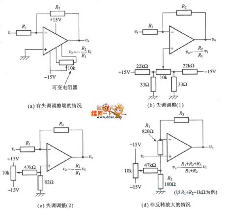
operational amplifer maladjustment regulator circuit diagram
Published:2011/5/5 8:41:00 Author: | Keyword: operational amplifer, maladjustment, regulator
View full Circuit Diagram | Comments | Reading(621)
TDA7498 two-channel audio power amplifier integrated circuit diagram
Published:2011/5/5 3:56:00 Author:Ecco | Keyword: two-channel , audio, power amplifier , integrated circuit

Philips TDA7498 is the two-channel audio power amplifier integrated circuit produced by Philips, it is widely used in high-fidelity audio, such as home audio, car audio, TV audio. 1. Features of functionTDA7498 integrated circuit contains two audio power amplifier circuits with the same functions, electronic volume control circuit, the standby control circuit, overheat protection and short circuit protection, output power per channel is 8W. 2. Pin functions and data TDA7498 IC uses 15-pin single in-line package, the pin functions and data are listed in Table 1. Table 1 shows TDA7498 integrated circuit pin functions and data.
(View)
View full Circuit Diagram | Comments | Reading(1858)
TDA7497 three-channel audio power amplifier integrated circuit diagram
Published:2011/5/5 3:52:00 Author:Ecco | Keyword: three-channel , audio , power amplifier , integrated circuit
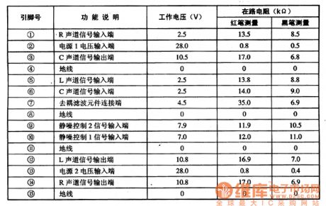
TDA7497 is the three-channel audio power amplifier integrated circuit produced by Philips, it is widely used in various hi-fi, such as TV audio, multimedia audio and so on. 1. Features of function TDA7497 integrated circuit includes three ways of audio amplifier circuits with the same functions, and it also has two independent mute functions, and it can execute squelch control on the main channel and center channel; it also sets overheating protection and short circuit protection. 2. Pin functions and data TDA7497 IC uses 15-pin single in-line package, the pin functions and data are listed in Table 1. Table 1 shows TDA7497 integrated circuit pin functions and data.
(View)
View full Circuit Diagram | Comments | Reading(1643)
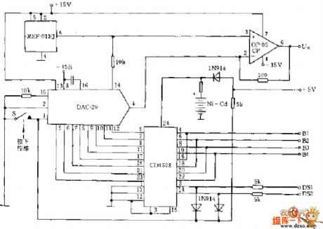
Digital voltage meter measurement circuit
Published:2011/5/5 3:35:00 Author:Christina | Keyword: Digital, voltage meter, measurement
View full Circuit Diagram | Comments | Reading(588)
secret code lock circuit
Published:2011/5/5 2:55:00 Author:Christina | Keyword: secret code, lock
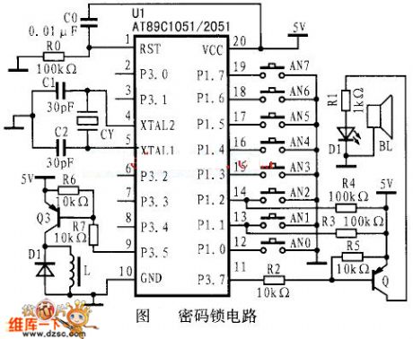
Figure: secret code lock circuit (View)
View full Circuit Diagram | Comments | Reading(1096)
Three-channel audio power amplifier integrated circuit diagram
Published:2011/5/5 2:46:00 Author:Ecco | Keyword: Three-channel , audio, power amplifier , integrated circuit
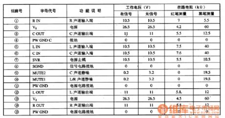
TDA7494 is the three-channel audio power amplifier integrated circuit produced by Philips, it is widely used in the high-fidelity home theater, television, audio and other systems. 1. Features of functionTDA7494 integrated circuit contains three-way audio power amplifier circuits with the same functions, two independent mute control circuits, it can execute independent mute control on the main channel and sub channel; it also has overheat, short circuit protection functions. 2. Pin functions and data TDA7494 integrated circuit uses the package with 15-pin in single row, the pin functions and data are listed in Table 1. Table 1 shows TDA7494 integrated circuit pin functions and data.
(View)
View full Circuit Diagram | Comments | Reading(1073)
STV8223 Intermediate frequency amplifier integrated circuit diagram
Published:2011/5/5 1:33:00 Author:Ecco | Keyword: Intermediate frequency, amplifier, integrated circuit
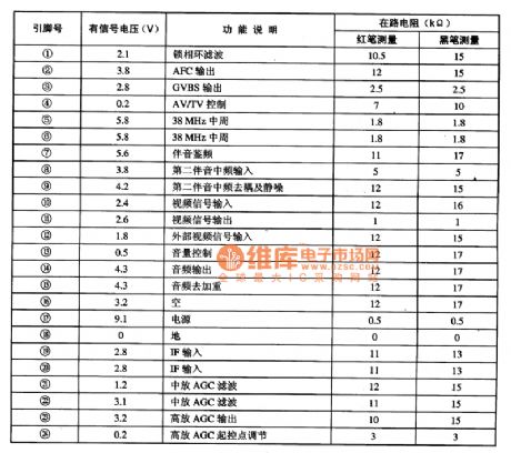
STV8223 is the intermediate frequency signal amplifier integrated circuit produced by SGS-THOMSON company in French, it is widely used in various domestic and imported large screen color television sets, such as Skyworth, TCL, Rover and other high-color television. 1. Features of functionSTV8223 IC mainly contains the PLL circuit, AV / TV control circuit, 38MHz frequency discriminator circuit, intermadite and high level radioactive AGC circuit, the audio signal amplification circuit, frequency circuit, electronic volume control circuit and other subsidiary function circuit. 2. Pin functions and data STV8223 IC uses 24-pin dual in-style package, the pin functions and data are listed in Table. STV8223 IC pin functions and data
(View)
View full Circuit Diagram | Comments | Reading(708)
FET logic probe circuit
Published:2011/5/4 18:55:00 Author:Christina | Keyword: FET, logic probe
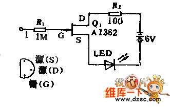
Field-effect transistor with high input impedance can make the LED light when the input port appears logic 1, and it will not produce the load effect on the monitored circuit.
(View)
View full Circuit Diagram | Comments | Reading(972)
869~894MHz Narrow-Band Amplification Circuit Composed Of RF2320/2360
Published:2011/5/5 0:58:00 Author:Robert | Keyword: 869~894MHz, Narrow-Band, Amplification
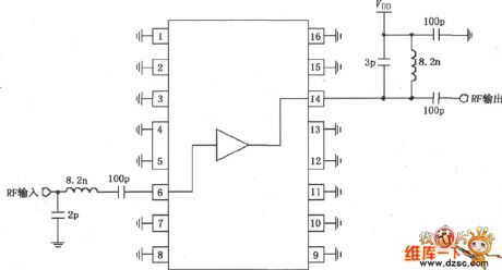
The picture shows the 869~894MHz narrow-band amplification circuit composed of RF2320/2360. The RF signal inputs from the 6 foot and outputed from the 14 foot through the amplifier. The 6 foot is coupling with internal amplifier, so it needs to add a 100pF blocking coupling capacitor (make up input matching networks with 8.2nH inductor). The 14 foot is output port and can be added to power Vdd through matching inductor. If users only consider aboutthe drift current, it only needs to add one choke coil.
(View)
View full Circuit Diagram | Comments | Reading(572)
RF2360 Linear General Purpose Amplifier Pin Circuit
Published:2011/5/5 0:58:00 Author:Robert | Keyword: Linear, General Purpose Amplifier, Pin
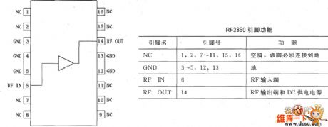
The RF2360 is a general purpose, low-cost, high-linearity RF amplifier IC, and is manufactured on an advanced gallium arsenideheterojunction bipolar transistor (HBT) process. It has been designed for using as an easily cascadable 75Ω gain block with a noise figure of less than 2dB. Gain flatness is better than 0.5dB from 5MHz to 1000MHz, and high linearity makes this part ideal for cable TV applications. Other applications are include IF and RF amplification in wireless voice and data communication products which operating in frequency bands up to 1000MHz. The device is self-contained with 75Ω input and output impedances providing less than 2:1 VSWR matching. RF2360 is featured in a SOP-16 squaredbatwing package, and its pinout is shown in the picture below.
(View)
View full Circuit Diagram | Comments | Reading(709)
RF2347 Low Noise PA Driver Amplifier Pin Circuit
Published:2011/5/5 1:02:00 Author:Robert | Keyword: Low Noise, PA Driver, Amplifier, Pin
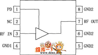
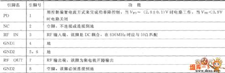
The RF2347 is a low noise amplifier with a very high dynamic range designed for digital cellular applications at 900MHz. As an outstanding low noise amplifier or powerdriver amplifier,the devicedoes well in solutions ofthe problem oflow transmit noise powerconcerned by digital subscriber. When used as a PA driver amplifier, the IC can be operated directly from a single cell Li-ion battery, and also it has a power down feature that can completely use normal small shutdown devices. The IC is featured in a standard miniature 8-lead plastic MSOP package and its pinout andfunctionsare shown in the picture below.
(View)
View full Circuit Diagram | Comments | Reading(581)
LA6510-geomagnetic correction output amplifier integrated circuit
Published:2011/5/4 22:44:00 Author:Nicole | Keyword: geomagnetic correction, output amplifier
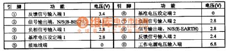
LA6510 is a geomagnetic correction output amplifier integrated circuit which is produced by Sanyo, it is used as geomagnetic correction singal amplifier in new type large screen, large screen PIP and color TV.
1, Function and feature
LA6510 integrated circuit contains two-way same function amplifier circuit, reference voltage steady voltage setting circuit and other assist functional circuit.
2, Pin function and data
LA6510 integrated circuit adopts 10-pin package, the pin function and data of this integrated circuit is shown in chart1.
(View)
View full Circuit Diagram | Comments | Reading(959)
TC99ON, TC909OF comb filter integrated circuit
Published:2011/5/4 9:31:00 Author:TaoXi | Keyword: comb filter

The TC99ON and TC909OF are designed as the comb filter integrated circuit which is produced by the TOSHIBA company, and this device can be used in variety of domestic and imported TVs such as the Changhong NC-6, CN-7.etc.
The TC9090N and TC9090F are in the 28-pin dual in-line package, the pin functions and data is as shown in table 1.
Table 1. The TC9090N, TC9090F IC's pin functions and data (View)
View full Circuit Diagram | Comments | Reading(620)
High Input Impedance of Broadband Amplifier Circuit
Published:2011/5/4 7:30:00 Author:Joyce | Keyword: High Input, Impedance, of Broadband, Amplifier, FX110
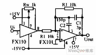
High input impedance of broadband amplifier circuit is shown in the graph below.The first level is a voltage follower, with the typical value of input bias current 1nA ,difference-mode input resistance 1012Ω, input capacitance 1.5 pF and small signal bandwidth 20MHz. The second level has negative feedbacks, and C2 will constitute a feed-forward compensation. The potentiometer is used to adjust the offset voltage of FX110.The accuracy of resistance R1, R2 is 1%. (View)
View full Circuit Diagram | Comments | Reading(633)
TDA8946J two-channel BTL audio power amplifier integrated circuit diagram
Published:2011/5/4 21:34:00 Author:Ecco | Keyword: two-channel, BTL, audio , power amplifier, integrated

TDA8946J is the BTL is audio power amplifier integrated circuit produced by Philips, it is widely used in high-fidelity home theater, television sound audio, multimedia audio and noon and so on. 1. Features of functionTDA8946J integrated circuit contains two BTL circuit with the same function, static noise and the standby control circuit, thermal protection and short protection circuit. When Vcc = 8V, RL = 8Ω, each channel output power is 15W. 2. Pin functions and data TDA8946J IC uses the package with 17 pin in single row, the pin functions and data are listed in Table 1. Table 1 shows TDA8946J integrated circuit pin function and data.
(View)
View full Circuit Diagram | Comments | Reading(1866)
TBA800 5W Amplifier Circuit
Published:2011/5/4 8:48:00 Author:Robert | Keyword: 5W, Amplifier
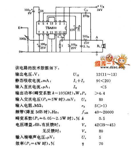
TBA800 5W Amplifier Circuit is shown below.
This circuit's technical data is concluded here:
Output voltage, V: U12 12(11~13)
Static Sink Current, mA:I1+I3 9(<20)
Input DC current, uA: I8 <5
Output power, (Distortion coefficientk=10%), W: Po >4.4
Input AC voltage (Po=5W), mW:U8 80
Input resistance, MΩ:r8 5(>1)
Bandwidth (3dB down),Hz: f3dB 40~20000
Distortion coefficient(Po=0.05~2.5W),%k: 0.5
Voltage gain, dB, with feedback:Vu 42(39~45); without feedback:Vu 80
Input port Noise Voltage,uV:Ut 5
Effciency(Po=4W),%:η 70
(View)
View full Circuit Diagram | Comments | Reading(2731)
Integrated Amplifier Circuit
Published:2011/5/4 9:36:00 Author:Robert | Keyword: Integrated Amplifier
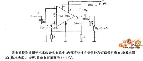
The integrated amplifier circuit is shown below. This circuit is specially suit for the car radio circuits. With internal thermal overload protection, its loading resistance is 2Ω and output power is 10W, and its supply voltage range is from 5V to 18V.
(View)
View full Circuit Diagram | Comments | Reading(505)
difference single-end headphone amplifier circuit
Published:2011/5/4 19:27:00 Author:Christina | Keyword: difference single-end, headphone amplifier

View full Circuit Diagram | Comments | Reading(777)
OP headphone amplifier circuit
Published:2011/5/4 19:30:00 Author:Christina | Keyword: OP, headphone amplifier
View full Circuit Diagram | Comments | Reading(684)
operational amplifier basic circuit diagram
Published:2011/5/4 9:44:00 Author: | Keyword: operational amplifier, basic circuit
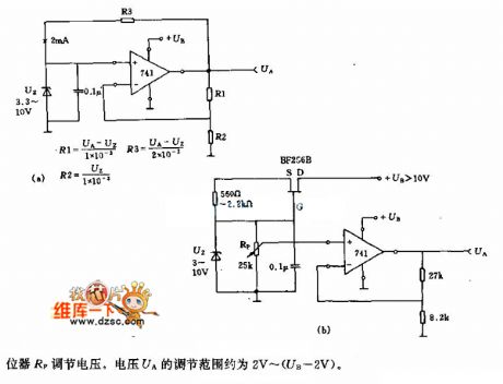
Rp regulates voltage.The regulation range of UA is about 2V~(UB-2V).
(View)
View full Circuit Diagram | Comments | Reading(693)
| Pages:231/250 At 20221222223224225226227228229230231232233234235236237238239240Under 20 |
Circuit Categories
power supply circuit
Amplifier Circuit
Basic Circuit
LED and Light Circuit
Sensor Circuit
Signal Processing
Electrical Equipment Circuit
Control Circuit
Remote Control Circuit
A/D-D/A Converter Circuit
Audio Circuit
Measuring and Test Circuit
Communication Circuit
Computer-Related Circuit
555 Circuit
Automotive Circuit
Repairing Circuit