
Index 87
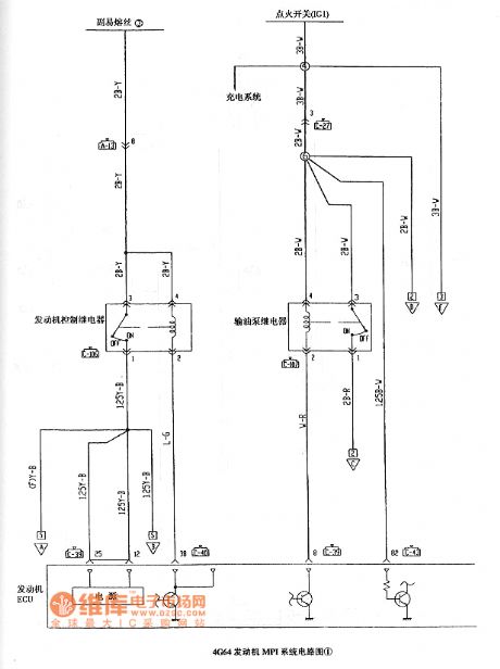
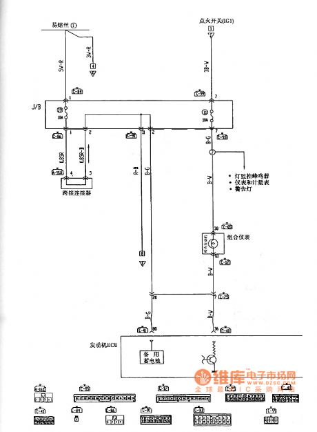
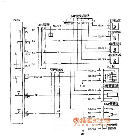
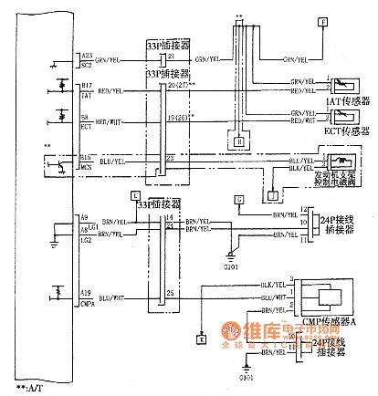
Liebao SUV 4G64 engine MPI system circuit diagram
Published:2011/5/13 0:59:00 Author:Ecco | Keyword: Liebao , SUV, engine , MPI system
View full Circuit Diagram | Comments | Reading(843)
Zastava 7200 starting, ignition system circuit diagram
Published:2011/5/13 2:52:00 Author:Ecco | Keyword: Zastava, starting, ignition system
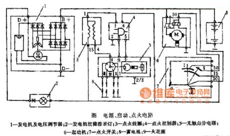
1 - generator and voltage regulator; 2 - generator fault indicator; 3 - ignition coil; 4 - ignition controller; 5 - non-contact distributor; 6 - starter; 7 - ignition switch; 8 - battery; 9 - spark plug (View)
View full Circuit Diagram | Comments | Reading(757)
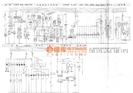
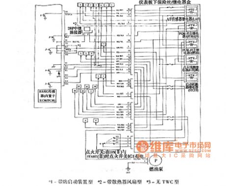
Merrie 3-cylinder engine Marui Li single point injection system circuit diagram
Published:2011/5/13 1:34:00 Author:Ecco | Keyword: Merrie , 3-cylinder, engine , Marui Li , single point, injection system
View full Circuit Diagram | Comments | Reading(1150)
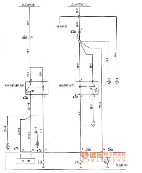
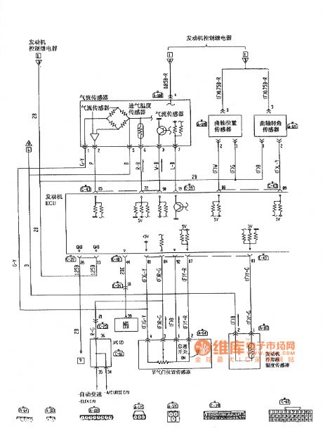
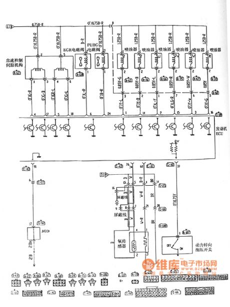
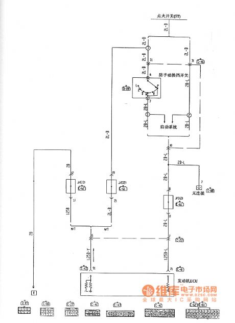
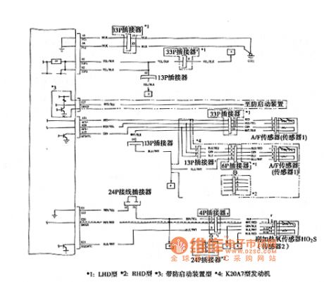
Liebao SUV 6G72 engine MPI system circuit diagram
Published:2011/5/13 0:55:00 Author:Ecco | Keyword: Liebao, SUV, engine , MPI system
View full Circuit Diagram | Comments | Reading(1707)
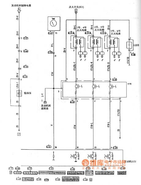
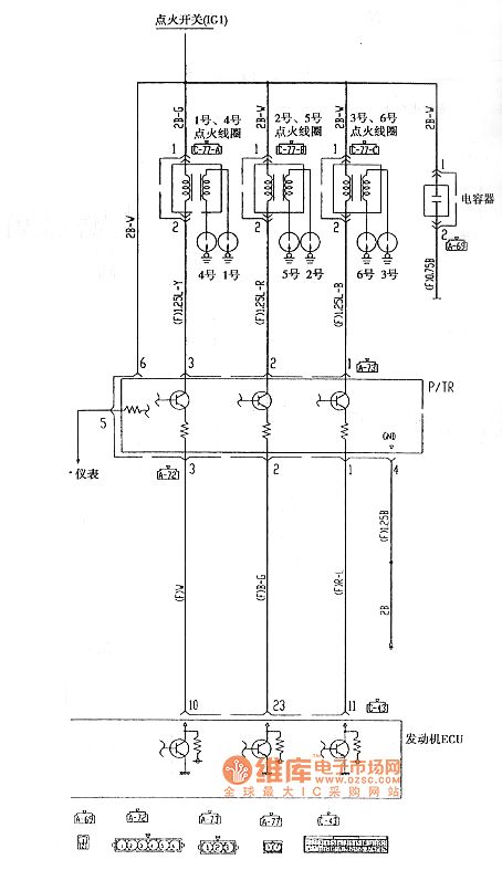
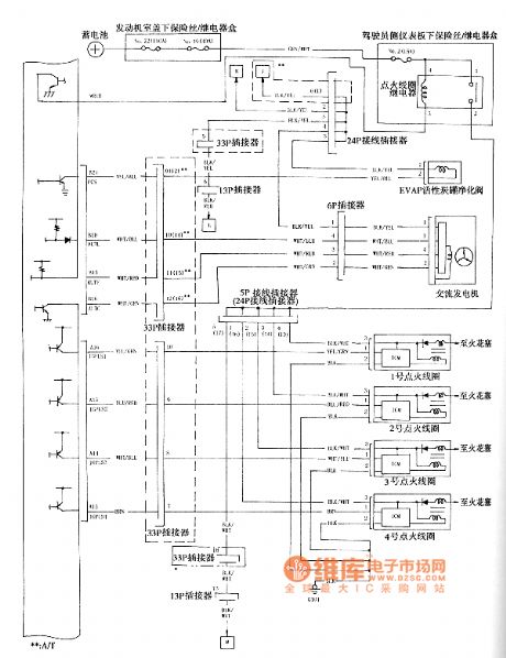
Liebao SUV 6G72 engine ignition system circuit diagram
Published:2011/5/13 0:50:00 Author:Ecco | Keyword: Liebao , SUV , engine, ignition system
View full Circuit Diagram | Comments | Reading(1141)
Hanging hydro-generator structure diagram
Published:2011/5/12 22:27:00 Author:Ecco | Keyword: Hanging , hydro-generator, structure
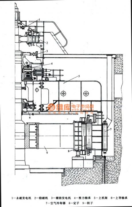
1 - Water magnetic generator, 2 - exciter, 3 - auxiliary generators, 4 - thrust bearing, 5 - on the rack, 6 - Upper Guide Bearing, 7 - air cooler, 8 - Stator, 9 - Rotor (View)
View full Circuit Diagram | Comments | Reading(1199)
Honda Accord 2003 engine circuit diagram
Published:2011/5/12 22:11:00 Author:Ecco | Keyword: Honda, Accord , engine

View full Circuit Diagram | Comments | Reading(3254)
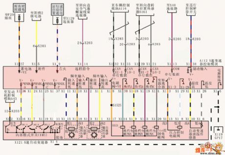
Shanghai Buick Royaum V63.6L car automatic transmission control circuit diagram(1)
Published:2011/5/12 21:42:00 Author:Nicole | Keyword: Shanghai Buick Royaum, V63.6L car, automatic transmission
View full Circuit Diagram | Comments | Reading(580)
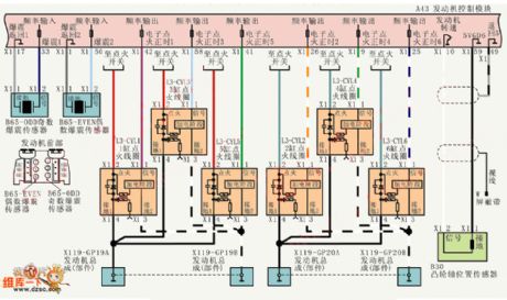
Shanghai Buick Royaum V63.6L car ignition and detonation control circuit diagram
Published:2011/5/12 21:44:00 Author:Nicole | Keyword: Shanghai Buick Royaum, V63.6L car, ignition, detonation control
View full Circuit Diagram | Comments | Reading(488)
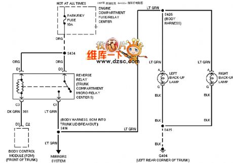
Cadillac deville reverse class circuit diagram
Published:2011/5/12 21:22:00 Author:Nicole | Keyword: Cadillac deville, reverse class
View full Circuit Diagram | Comments | Reading(492)
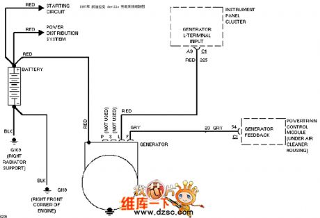
Cadillac deville charging system circuit diagram
Published:2011/5/12 21:17:00 Author:Nicole | Keyword: Cadillac deville, charging system
View full Circuit Diagram | Comments | Reading(2846)
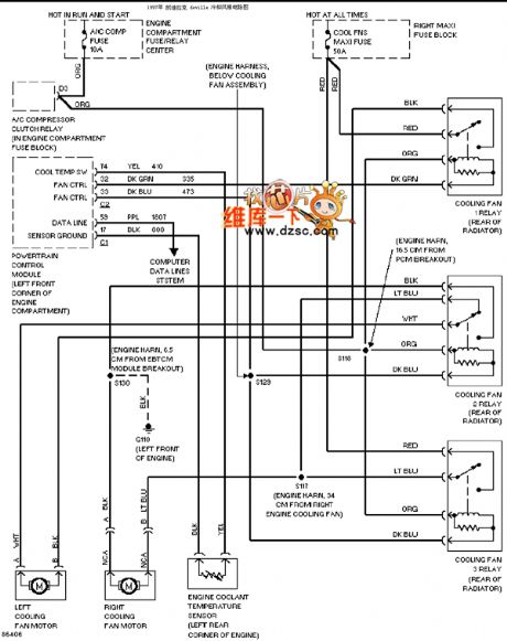
Cadillac deville cooling fan circuit diagram
Published:2011/5/12 21:16:00 Author:Nicole | Keyword: Cadillac deville, cooling fan
View full Circuit Diagram | Comments | Reading(810)
China vehicle engine circuit diagram
Published:2011/5/8 6:29:00 Author:Rebekka | Keyword: China vehicle engine circuit
China vehicle engine circuit diagram. (View)
View full Circuit Diagram | Comments | Reading(531)
Chinese car wipers spray washing device circuit diagram
Published:2011/5/8 6:09:00 Author:Rebekka | Keyword: Chinese car wipers spray washing device
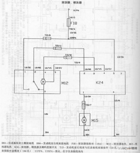
Chinese car wipers spray washing device circuit diagram. (View)
View full Circuit Diagram | Comments | Reading(569)
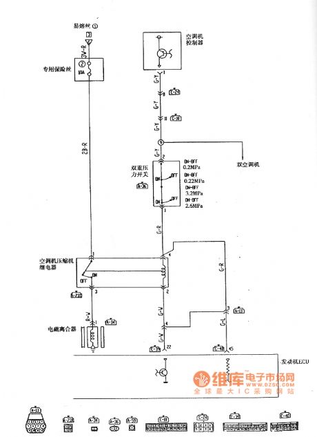
Mitsubishi Pajero light sport utility vehicle defrost air conditioning circuit diagram
Published:2011/5/8 11:34:00 Author:Rebekka | Keyword: Mitsubishi Pajero , light sport utility vehicle
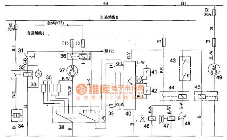
31 defroster switch; 32 defrost relay; 33 defrost indicator; 34 defroster; 35 resistor; 36 blower relay; 37 blast motor; 38 blower switch; 39 air conditioning switch; 40 air conditioning controller; 41 air temperature sensor; 42 inlet temperature sensor; 43 dual pressure switch (LON-OFF: O · 2MPa, OFF-ON: O · 23MPa; H: ON-OFF : 3.8 MPa, OFF-ON: 3.2 MPa); 4 air conditioning compressor relay; 45 condenser fan motor relay; 46 increased idle speed solenoid valve; 47 electromagnetic clutch; 48 engine temperature switch; 49 condenser fan motor; 68 the fire switch; 1 battery; 172 headlamp washer relay. (View)
View full Circuit Diagram | Comments | Reading(3356)
Shanghai GM Regal 2.0L intake temperature sensor connector terminal and connecting circuit diagram
Published:2011/5/12 1:23:00 Author:Nicole | Keyword: Shanghai GM Regal, intake temperature sensor, connector terminal
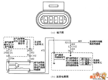
Shanghai GM Regal 2.0L intake manifold absolute pressure sensor and intake temperature sensor connector terminal and connecting circuit diagram
The intake manifold absolute pressure sensor and the intake temperature sensor are made into one, they are fixed to exhaust manifold. The connecting circuit of these two sensors connector terminal and electronic control unit is shown as below.
Intake temperature sensor is a negative temperature coefficient thermal resistor, the motor electronic control unit provides 5V power supply by its internal resistance.
When it is idle speed(high vacuum), the intake manifold absolute pressure sensor MAP output singal is lower than 2.0V; when the ignition switch is turned on and the motor does not run, the throttles are all open(low vacuum), it is higher than 4.0V.
(View)
View full Circuit Diagram | Comments | Reading(471)
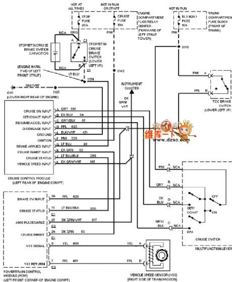
Cadillac deville cruise control circuit diagram
Published:2011/5/12 21:03:00 Author:Nicole | Keyword: Cadillac deville, cruise control
View full Circuit Diagram | Comments | Reading(1162)
Cadillac deville electronic suspension circuit diagram
Published:2011/5/12 21:00:00 Author:Nicole | Keyword: Cadillac deville, electronic suspension
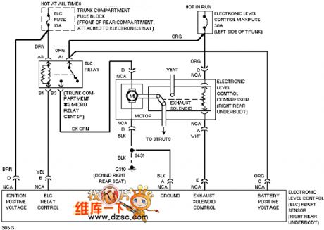
View full Circuit Diagram | Comments | Reading(621)
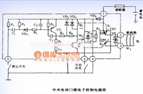
The central power door locks electronic control circuit diagram of Santana 2000
Published:2011/5/12 20:48:00 Author:Ecco | Keyword: central , power door locks , electronic control, Santana 2000
View full Circuit Diagram | Comments | Reading(610)
Storage Battery Voltage Monitor (1)
Published:2011/5/12 3:29:00 Author:Sue | Keyword: Storage, Battery, Voltage, Monitor
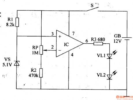
Working Principle:
As seen in the figure 7-48, the storage battery voltage monitor circuit consists of operational amplifier integrated circuit IC, resistor R1-R3, potentiometer RP, zener diode VS, power switch S and LED VL1,VL2.
When S is connected, storage battery GB's +12V voltage provides IC's 3 pin with 5.1Vreference voltage after being limited and stablized by R and VS. While another voltage provides IC's 2 pin with sampling voltage after being divided by RP and R2.
When GB's terminal voltage exceeds 10.2V, IC outputshigh level because of 2 pin's voltage is higher than 3 pin's. So VL1 and VL2 are not illuminated.
When GB's terminal voltage doesn't reach 10.2V, IC outputslow level and VL1 VL2 are illuminated, indicating that battery voltage has reduced to preset threshold voltage, which means charging is needed.
Choice of components:
R1-R3: 1/4W metal film or carbon film resistor.
RP:Organic composition solid potentiometer or variable resistor.
VL1,VL2:φ5mm high-brightness red LED.
VS:1/2W,5.1V silicon voltage stablizing diode.
IC:μA741 integrated operational amplifier.
S: Miniture unipolar toggle swtich. (View)
View full Circuit Diagram | Comments | Reading(689)
| Pages:87/164 At 2081828384858687888990919293949596979899100Under 20 |
Circuit Categories
power supply circuit
Amplifier Circuit
Basic Circuit
LED and Light Circuit
Sensor Circuit
Signal Processing
Electrical Equipment Circuit
Control Circuit
Remote Control Circuit
A/D-D/A Converter Circuit
Audio Circuit
Measuring and Test Circuit
Communication Circuit
Computer-Related Circuit
555 Circuit
Automotive Circuit
Repairing Circuit