
Index 358
μA747 dual power universal dual op amp circuit diagram
Published:2011/5/15 6:25:00 Author:Rebekka | Keyword: dual power universal, dual op amp
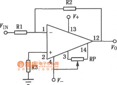
μA747 is a high gain dual op amp. The two op amps have a common bias and the negative power leads lines respectively. They have their independent functions in working mode. Its characteristics are: No external frequency compensation. It has a short-circuit protection, a wide differential mode a common mode input voltage range, low power consumption. It will not be blocked in the working mode. It can be used as integrator, summing amplifier and general feedback amplifier. The similar or direct substitution models are: CF747MT, CF747CT, CF747MD, CF747CD, CF747MJ, CF747CJ, CF747CP, SG747 and so on. The typical application circuit is shown as above. (View)
View full Circuit Diagram | Comments | Reading(900)
The bridge driving circuit composed of the OPA502
Published:2011/7/2 1:26:00 Author:Rebekka | Keyword: bridge driving
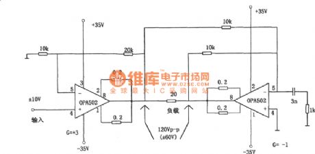
The figure shows the the bridge drive circuit composed of the OPA502. The OPA502 on the left uses the same phase input methods, so its input resistance is very high, the input signal is directly sent into the same phase input (pins 4), its positive and negative output terminals of the external SFCL RCL = 0.2 Ω. Thus the output current limit is 4 A. In the case of the parameters (the feedback resistance for 20 k Ω, inverse end resistance land is 10 k Ω), the voltage amplifier multiples is 3. The left output voltage of the OPA502 reaches to the load. (View)
View full Circuit Diagram | Comments | Reading(369)
Metal Detector
Published:2011/7/20 5:58:00 Author:Sue | Keyword: Metal, Detector
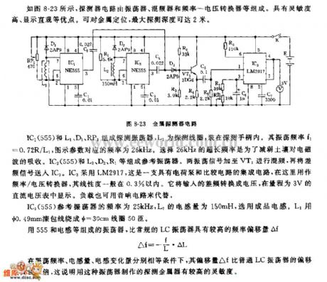
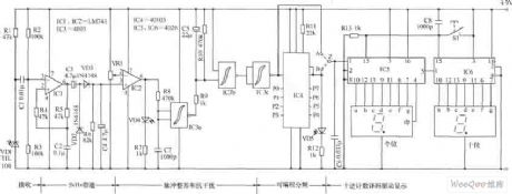
As seen in figure 8-23, the detector circuit consists of oscillator, mixer, frequency to voltage converter. It has many advantages such as high sensitivity, direct display. It can fix the position of metal and the deepest detection depth can reach 2 meters.
IC1(555) and L1,D1,RP1 will compose detecting oscillator. L1 is detecting coil which will be put in the detecting handle. Its oscillate frequency f1=0.72R/L1. The parameter's corresponding frequency in the figure is 26kHz. To choose the extra long frequency of 26kHz can abate the soil's absorption of the electromagnetic wave. IC2(555) and L2,D2,R1 will compose referency oscillator. The two oscillate signals will be put on VT1 to be mixed, and then the difference frequency signal will be put on IC3. IC3 uses LM2917. It is a integrated circuit with charge pump and comparator circuit and is used as frequency to voltage converter. Its degree of linearity is usually within 0.3%. It will convert the input difference frequency into voltage which will be shown in the direct current voltmeter with a range of 3V. The load can also be replaced by audio circuit. (View)
View full Circuit Diagram | Comments | Reading(4352)
The circuit of counter composed of digital circuit
Published:2011/7/14 23:12:00 Author:Fiona | Keyword: counter, digital circuit
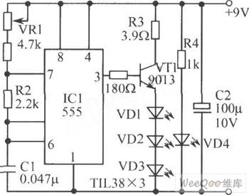
The digital circuit composed of counter as shown in figure uses infrared ray as the detection signals,a small device for scanning count moving target is applicable to the production line, it can count fast and accurate the moving items on the conveyor belt. It can also be used for other purpose, such as counting the passagers of enterance or exit and so on. The circuit’s characteristic is the simple structure, making easy, economical and practical. There is also a most prominent advantage that it can count the different shading number of items directly.
(View)
View full Circuit Diagram | Comments | Reading(531)
the smart battery charger circuit that using a single transistor
Published:2011/7/14 23:09:00 Author:Fiona | Keyword: the smart battery charger, using a single transistor
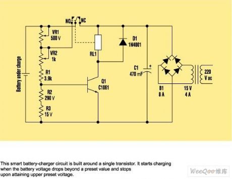
circuit work
First, the variable voltage power supply is fixed at 13.3 V dc - This is battery electricity voltage,and is connected to the battery's connection point of this circuit.The slider of VR1 is transferred to the top of the battery positive electrode. The slider of VR2 should be adjusted to one end connecting VR1. The transistor starts to work to shunt VR1. Then,the slider of VR1 is adjusted to the other side, that is one end of connecting VR2.
Now,let the test voltage is 11.8 V dc, which is the voltage when the battery runs out. Then, adjust VR2 so that the transistor no longer work. Test voltage is further increased to 13.3 V dc, adjust VR1 to make transistors work. By setting the upper and lower voltage, NC point is connected to the circuit. A battery charger is ready now.
(View)
View full Circuit Diagram | Comments | Reading(803)
The system drive circuit of the 3-phase permanent magnet brushless DC motor driven by IR2130
Published:2011/7/20 4:00:00 Author:Borg | Keyword: system drive circuit, 3-phase, permanent magnet, brushless DC motor
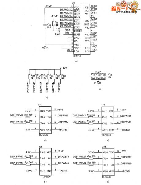
The system drive circuit of the 3-phase permanent magnet brushless DC motor driven by IR2130 is shown as above.
(View)
View full Circuit Diagram | Comments | Reading(1045)
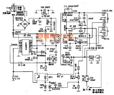
Single stage PFC high brightness LED driver circuit achieving 700 mA current
Published:2011/7/19 8:49:00 Author:Fiona | Keyword: Single stage, high brightness, driver

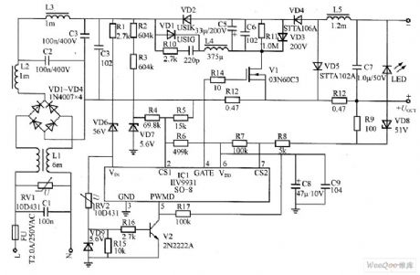
Figure is single-stage PFC LED driver power supply.With the increasing use of LED,especially extensive use of the offline type switch power supply composed of a sample circuit,it surely makes the power grid's power factor severely reduce and the power grid's reactive power consumption increase finally.Therefore increasing the switching power supply power factor and reducing harmonic current have become the development direction of LED lighting power supply in the future.This section describes using the falling rise and fall without transformer single-stage circuit,it can provide high conversion efficiency,it is low-cost,high reliability and high-power LED driver power supply.
(View)
View full Circuit Diagram | Comments | Reading(666)
Low pass active filter circuit
Published:2011/7/20 0:43:00 Author:Fiona | Keyword: Low pass, active filter

Low pass active filter circuit is shown as above:
(View)
View full Circuit Diagram | Comments | Reading(632)
High pass active filter circuit
Published:2011/7/20 0:43:00 Author:Fiona | Keyword: High pass, active filter
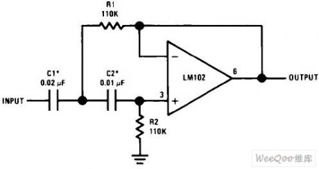
High pass active filter circuit is shown as above:
(View)
View full Circuit Diagram | Comments | Reading(700)
The radiation thermometer circuit composed of NJL9102F/9103 sensors
Published:2011/7/20 0:38:00 Author:Borg | Keyword: radiation thermometer
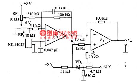
This is the radiation thermometer circuit composed of NJL9102F/9103 sensors. NJL9102F/9103 is a sensor which combines the thermopile and the temperature compensation diode, compared to the traditional thermopile, the circuit is simple and the temperature compensation effect is better. In figure (a) is a simple radiation thermometer circuit. In the circuit, the internal resistance of the sensor is high, which is about 500kΩ. A1 is a computing amplifier with high impedance and any kind of FET input type is OK.
(View)
View full Circuit Diagram | Comments | Reading(1348)
The thermometer circuit composed of MAX6577 integrated temperature sensors
Published:2011/7/20 0:29:00 Author:Borg | Keyword: thermometer circuit, temperature sensors
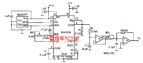
This is the thermometer circuit composed of MAX6577 integrated temperature sensors, the tested temperature range is 40一+125℃. Both RP1 and RP2 are used to regulate the deviation of the output voltage U. For example, the ℃ thermometer requires the output change to be lOmV/℃, when it is 0℃, by adjusting RP1, the output will be 0V; when it is -10℃, by adjusting RP2, the output will be -1OOmV.
MAX6577 outputs square waves whose frequency is in positive proportion to the thermodynamics temperature. (View)
View full Circuit Diagram | Comments | Reading(558)
The bridge voltage transformer
Published:2011/7/21 0:05:00 Author:Borg | Keyword: voltage transformer
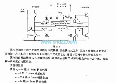
The circuit is equal to 2 serial transformers of parallel connection, which works in push-pull way, so the power supply doesn't need to have middle point. The left-upper and right-lower transistors of the transformer are always at the close or open state at the same time, and their states are opposite to the other two transistors. The circuit starts to oscillate with the help of the additional coil, the coil generates the impact current by key T or pulse contactor. The amplitude of the oscillation pulse is limited by the resistor. (View)
View full Circuit Diagram | Comments | Reading(407)
The dual limit temperature alarm circuit (2)
Published:2011/7/20 23:50:00 Author:Borg | Keyword: temperature alarm circuit
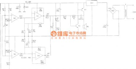
Element selectionR1~R16 are selected with the 1/4 metal film resistor or the carbon film resistor; RT is the negative coefficient thermistor; RP1 and RP2 are the small multi-turn potentiometers; C1~C4, C6 and C7 are the aluminum electrolytic resistors of 16V; C5 is the dacron or monolith capacitor; VD1~VD3 are the 1N4148 silicon switches diodes; VL1~VL3 are the high brightness LED of φ3mm, VL1 is yellow, VL2 is red, VL3 is green. (View)
View full Circuit Diagram | Comments | Reading(439)
The SIPMOS control circuit with transformer LEV separator
Published:2011/7/20 23:40:00 Author:Borg | Keyword: control circuit, LEV separator
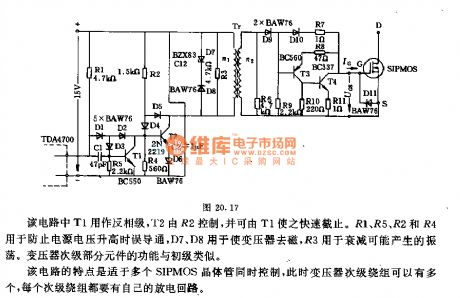
The T1 in the circuit works as the phaser reversing state, T2 is controlled by R2, and T1 can make it blocked quickly. R1, R5, R2 and R4 are used to prevent from wrongly conducting when the power supply voltage rises, D7 and D8 are used to remove the magnetism of the transformer, R3 is to reduce the oscillation that may happen. The second part of the transformer has almost the same functions with the first stage. The feature of the circuit is that it can simultaneously control more than one SIPMOS transistors. (View)
View full Circuit Diagram | Comments | Reading(416)
The SIPMOS transistor inter-compensation Darlington control circuit
Published:2011/7/20 23:18:00 Author:Borg | Keyword: SIPMOS, transistor, Darlington control circuit
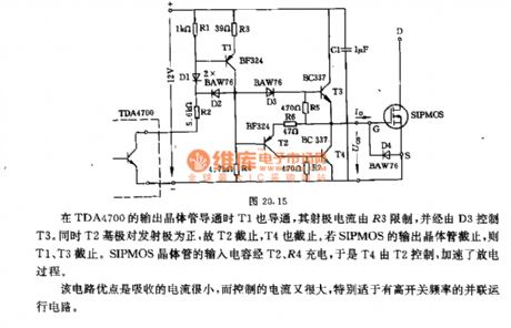
T1 is conducting when the output transistor of TDA4700 is conducting, the emitter current is limited by R3 and T3 is controlled by D3. At the same time, T2 basic pole is positive to the emitter, so T2 is blocked, so is T4. If the output transistor of SIPMOS is blocked, both T1 and T3 are blocked. The input capacitor of SIPMOS transistor is charged by T2 and R4, so T2 controls T4, which accelerates the discharging process. The virtue of the circuit is that the attracted current is low but the controlled current is high. (View)
View full Circuit Diagram | Comments | Reading(511)
Darlington power transistor driver circuit diagram
Published:2011/7/26 2:00:00 Author:Ecco | Keyword: MOSFET, Darlington , power transistor, driver circuit
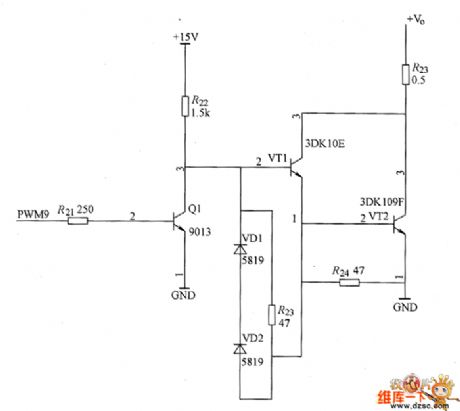
Bipolar power transistor (GTR or BJT) is the transistor with ice ball structure, and its junction temperature is up to 200 ℃, and under the aerospace with extremly serious environmental conditions, it has other advantages which can not be replaced. In addition, GTR has lower on-state saturation voltage drop than ICBT and MOSFET under high voltage, high current (under 10A load current, the on-state saturation voltage is less than 0.2V), it can maximize to improve the efficiency of the convertion.
(View)
View full Circuit Diagram | Comments | Reading(1635)
LA7910 frequency range decoding IC
Published:2011/7/25 22:27:00 Author:Ecco | Keyword: frequency range decoding
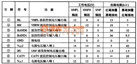
LA7910 frequency range decoding IC produced by Sanyo is widely used in a variety of screen color TV. 1. Features and functions LA7910 IC includes three-way electronic switching circuit, frequency range decoding circuit and so on. 2. pin functions and data LA7910 IC uses a separate 9-pin package, and the integrated circuit pin functions and data are listed in Table 1.
(View)
View full Circuit Diagram | Comments | Reading(912)
MC44608P45, MC44608P75, MC44608P100 switching power thick film IC diagram
Published:2011/7/25 21:32:00 Author:Ecco | Keyword: switching power, thick film IC
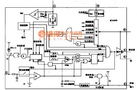
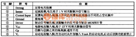
MC44608 is the low-power, high-performance, high-voltage series of switching power thick film circuit produced by ON Semiconductor, and it is widely used in the TCL latest big-screen TV. 1. features and functionsMC44608 series contains a no-loss high-voltage integrated circuit start circuit, which can eliminate the traditional start-up resistor, and the standby power consumption is only lW. It also integrates a pulse oscillation circuit, overvoltage / overcurrent / overheat protection circuit. The manifold block diagram is shown as the chart.
(View)
View full Circuit Diagram | Comments | Reading(2197)
The photosensitive diode circuit
Published:2011/7/25 20:35:00 Author:Christina | Keyword: photosensitive diode
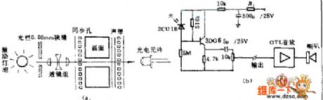
(a) is the black & white changing voice signal soundtrack which is recorded on the film, it is the sound motion picture. When the machinery gear drives the synchronous holes of the movie film, the light gets through the pictures, and is amplified by the projection lens to project the picture on the projection screen, this is the activity movies. When the film is moving, the soundtrack is moving too; the light which is sent out by the incentive bulb changes into a beam of light through the 0.05mm slit, and it projects to the soundtrack through the lens group.
(b) is the photosensitive diode circuit of the motion-picture machine.
(View)
View full Circuit Diagram | Comments | Reading(621)
Portable emergency light circuit with the automatic stop-charging function
Published:2011/7/25 2:35:00 Author:Christina | Keyword: Portable, emergency light, automatic, stop-charging function
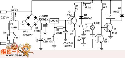

After the power is connected, if you press the sw1, the charging indicator light led will turn on, at this time the storage battery is lack of electricity, the e pole voltage of q1 is lower than the b pole voltage, so q1 and q2 cut off, q3 conducts to close the relay, the J1-1 closes to get in the self-locking state, J1 releases, the power cuts off, the charging stops, at the same time the charging indicator light led turns off. In the figure, the d1 is the isolation diode, it can be used to prevent the reverse discharge of the storage battery, you can make the circuit charge the storage batteries with different voltage by adjusting rw1.
(View)
View full Circuit Diagram | Comments | Reading(1694)
| Pages:358/471 At 20341342343344345346347348349350351352353354355356357358359360Under 20 |
Circuit Categories
power supply circuit
Amplifier Circuit
Basic Circuit
LED and Light Circuit
Sensor Circuit
Signal Processing
Electrical Equipment Circuit
Control Circuit
Remote Control Circuit
A/D-D/A Converter Circuit
Audio Circuit
Measuring and Test Circuit
Communication Circuit
Computer-Related Circuit
555 Circuit
Automotive Circuit
Repairing Circuit