
Index 105
PROXIMITY_SWITCH
Published:2009/7/13 3:14:00 Author:May
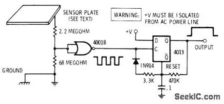
Hand brought near sensor plate induces 60-Hz power-line hum in section of quad two-input NOR gate. Hum is squared bygateand used to trip section of 4013 connected as retriggerable mono MVBR. Output of mono is clean from instant of first proximity until several milliseconds after moving hand away. Sensitivity depends on size of metal plate and on number of permissible false alarms from other noise sources nearby.-D. Lancaster, CMOS Cookbook, Howard W. Sams, Indianapolis, IN, 1977, p 278-282. (View)
View full Circuit Diagram | Comments | Reading(0)
DIGIT_LINE_DRIVER
Published:2009/7/16 3:53:00 Author:Jessie
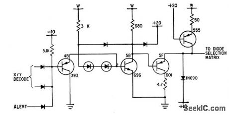
Uses diode steering to increase speed of memory.-A.Melmed, R,Shevlin, and W. Orvedahl, Diode Steering Increases Speed of Magnetic Memories, Electronics,34:37,p 68-70. (View)
View full Circuit Diagram | Comments | Reading(640)
LOGIC_SWITCH
Published:2009/7/13 3:09:00 Author:May
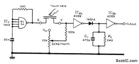
Can be used with batterypowered circuits because CMOS touch switch does not require body pickup of AC Iine hum for switchina action. Schmitt trigger IC1 forms 100 kHz oscillator. IC2a amplifies oscillator output and charges C1 through diode. When sensor is touched, oscillator output is severely attenuated, making C1 discharge and thereby changing output state of level detector IC2b. Sensor is 1-inch-square of double-sided printed-circuit board with lower side divided into two equal sections.-N. Sunderland, C.M.O.S. Touch Switch, Wireless World, May 1978, p 69. (View)
View full Circuit Diagram | Comments | Reading(1180)
LATCHING_TOUCH_SWITCH
Published:2009/7/13 3:05:00 Author:May
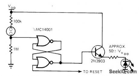
Uses LED as status display that substitutes for tactile feel of ordinary pushbutton switch. In reset state, LED is off. When touch contacts are bridged by resistance of finger, flip-flop changes state and LED comes on while output changes to high state.-V. Gregory, CMOS Touch Switches-Convenient, Less $ and Sexy, EDN Magazine, May 5, 1976, p 112. (View)
View full Circuit Diagram | Comments | Reading(1052)
TOUCH_SWITCH_1
Published:2009/7/13 3:03:00 Author:May
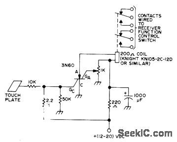
Performs function of switch by means of relay contacts when SCR is triggered by placing finger on touch plate. Values shown keep relay energized for 5-10 s after touch. Developed as replacement for switchtype controls on amateur radio receiver. Once SCR has fired, it conducts until charge on 1000-μF capacitor decreases enough to drop SCR current below minimum for conduction.-J. J. Schultz, Rapid Receiver Control Switching, 73 Magazine, Dec. 1973, p 67-69. (View)
View full Circuit Diagram | Comments | Reading(0)
TOUCH_SWITCH
Published:2009/7/13 3:01:00 Author:May
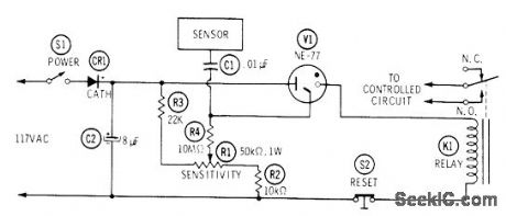
Uses NE-77 neon lamp, which is similar to NE-2 but has third electrode for triggering. When person touches metal sensor plate of switch, AC voltage picked up by body is applied to trigger electrode of neon, making it fire and energize 5000-ohm relay K1 (Potter & Brumfield RS5D or equivalent). Relay remains energized until S2 is opened to reset circuit. Adjust R1 so voltage applied to center electrode of V1 is just below trigger point.-J. P. Shields, How to Build Proximity Detectors & Metal Locators, Howard W.Sams, Indianapolis, IN, 2nd Ed., 1972, p 52-55. (View)
View full Circuit Diagram | Comments | Reading(0)
CAPACITANCE_TYPE_AIRCRAFT_FUEL_GAGE
Published:2009/7/16 5:49:00 Author:Jessie
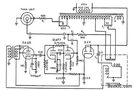
Indicates weight of fuel rather than volume. Uses self-balancing bridge, with concentric-tube capacitor mounted vertically in cell of tank to serve as one arm. With fuel in tank, servo drives bridge-rebalance potentiometer and indicator to new position corresponding to amount of fuel in tank.-J. Markus and V. Zeluff, Handbook of Industrial Electronic Control Circuits, McGraw-Hill, N.Y., 1956, p 21.
(View)
View full Circuit Diagram | Comments | Reading(1578)
TOUCH_CONTROLLED_SWITCH
Published:2009/7/16 5:48:00 Author:Jessie

Normal 30 to 100-pf capacitance of human body turns lamp on and off. Touching on antenna loads high-impedance network, reducing neon-lamp oscillator voltage below level required for firing four-layer pnpn germanium alloy transistor, and current that was shunted to ground through transistor now operates relay, turning on lamp. Touching off antenna reverses all conditions. -S. B. Gray, Home and Auto Controls, Electronics, 36:19, p 52-66. (View)
View full Circuit Diagram | Comments | Reading(835)
SCR_CONTROL
Published:2009/7/16 5:40:00 Author:Jessie
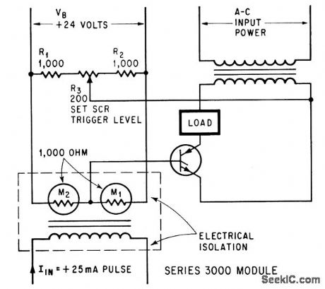
Firing angle and trigger level are controlled by magnetoresistor bridge.-R. M. Gitlin, Magnetoresistors Isolate Load From Control Circuit, Electronics, 38:3, p 54-59. (View)
View full Circuit Diagram | Comments | Reading(838)
TOGGLE_SWITCH
Published:2009/7/13 2:49:00 Author:May

Touching one 0.5-inch-square copperclad pattern on printed-circuit board turns switch circuit on by giving high out-put. Touching other plate turns switch off. LED between output and ground shows status of switch. For proper switching, circuit must con nect to line-operated DC power supply.-R. D. Wood, Replace Bulky Mechanical Switches with Touch Controls, EDN Magazine, April20, 1978, p 132-133. (View)
View full Circuit Diagram | Comments | Reading(1158)
Steam iron automatic protection circuit diagram
Published:2011/8/4 5:08:00 Author:Rebekka | Keyword: Steam iron, automatic protection
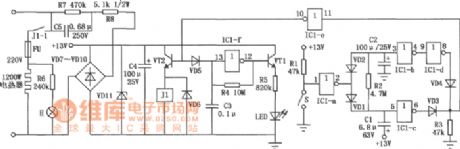
The circuit is shown as above, the commercial power passes C5, R7, R8 buck, VD7 ~ VDl0 commutating and VD11 regulator. The circuit provides operating voltage. When the iron is put horizontally, the mercury switch S downward about 15o and in a disconnected state. At this time, IC1-a outputs low level, C1 is charged by R2, ICl-c outputs low level, ICl-d has outputs low, VD3, VD4, IC1-e form NAND gate output high level, VT2 is turned on, relay Jl pulls in, then heating wire is heating, H neon lights are lit. (View)
View full Circuit Diagram | Comments | Reading(3666)
Light Control Cockcrow Ciruit
Published:2011/8/4 2:42:00 Author:May | Keyword: light control, cockcrow
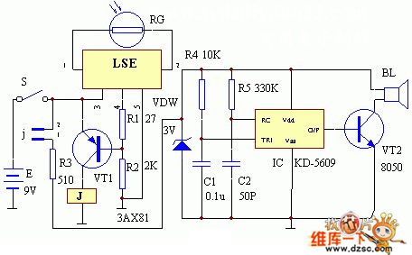
The circuit working principle of this set is shown in the diagram. At night, when there is no light shining on the photoresistor RG, the essential resistance of RG is very large, (larger than 50K) , so LSE's pin ①, ② is equal to open, LSE's pin ④ outputs low level, triode VT1 is break over, relay J excitation actuation, its normal close point j is opened, analog cockcrow circuit IC KD5609has no power and does not work. When daybreak, there is light shine on RG, the essential resistance of RG changeslower ( <50k) , at this moment , LSE' pin ④ outputs high level, triode VT1 is closed, relay J is released, its normal close point j is closed, analog cockcrow circuit is electrified and worked, andit sends clearly crow from the indicator speaker BL.
(View)
View full Circuit Diagram | Comments | Reading(844)
DEBOUNCE_FOR_TOUCH_SWITCH
Published:2009/7/13 2:47:00 Author:May
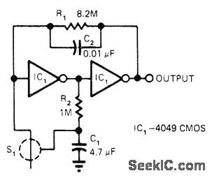
Two CMOS inverters respond to high-impedance path between electrodes of touch switeh to provide finger-touch sensitivity and positive switching action with minimum components. Large time constant of R1C1 requires wait of about 4 s before attempting to retrigger circuit. C2 prevents oscillation from 60-Hz pickup when electrodes are touched.-H. Manell, CMOS lnverters Implement Finger-Touch ON-OFF, EDN Magazine, Jan. 5, 1978, p 90. (View)
View full Circuit Diagram | Comments | Reading(1029)
OVERCURRENT_PROTECTION_FOR_400_V_SUPPLY
Published:2009/7/13 2:46:00 Author:May
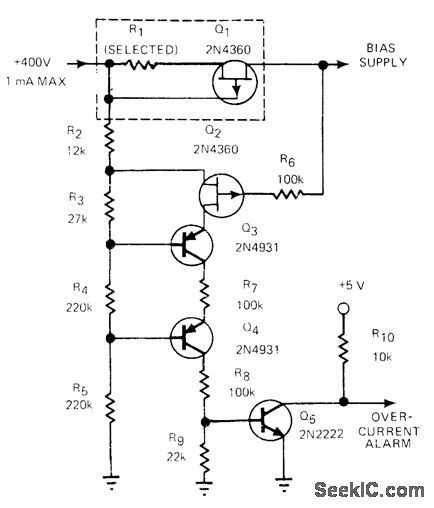
R1 and Q1 form current detector for bias supply. At normal current levels, voltage drop is very small and Q2 is reverse-biased. When current reaches 400 μA, voltage drop across R1 forces gate of Q1 to near pinchoff. Combined voltage drop across R1 and Q1 then becomes large so Q2 is forced almost to full conduction.Q3 and Q4 then tum on Q5, to provide overcurrent-alarm signal foractivating logic circuit that shuts off power supply.-J. P. Thompson, Overcurrent Alarm Protects HV Supply, EDN Magazine, Nov. 20, 1978, p 321-322. (View)
View full Circuit Diagram | Comments | Reading(1104)
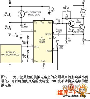
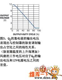
Anti-electromagnetic Interference PWM Fan Controller Circuit
Published:2011/8/4 2:39:00 Author:May | Keyword: Anti-electromagnetic Interference, PWM Fan Controller
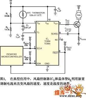
Microchip Tech-nology ( Microchip) company provides a type of fan refrigeration speed control system series product working on PWM mode, they are used for DC brushless cooling fans ( literature cite one) . We can use outside NTC(negative temperature coefficient) thermistor or a kind of PIC microcontroller from Microchip Tech-nology and SMBus serial data bus to utilize PWM waveform's dutyfactor to control fan speed.Figure 1 shows one kind of typical application ( literature cite two) description of TC664 and TC665 controller data information. It uses 1mF frequency control capacitor CF and fan controller IC1 to generatre a PWM pulse series, its nominal frequency is 30Hz,and thedutyfactor change range rely on temperatureis 30%-100%.
(View)
View full Circuit Diagram | Comments | Reading(2017)
TOGGLING_TOUCH_SWITCH
Published:2009/7/13 2:45:00 Author:May
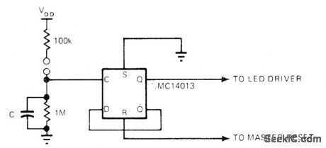
Uses half of Motorola MC14013 as flip-flop that changes state each time contacts are bridged by resistance of finger. For status display, LED driven by 2N3903 transistor can be added. Possible drawback is bouncing if finger is carelessly applied.-V. Gregory, CMOS Touch Switches-Convenient, Less $ and Sexy, EDN Magazine, May 5, 1976, p112. (View)
View full Circuit Diagram | Comments | Reading(876)
UNIJUNCTION_CONTROL_0F_MVBR
Published:2009/7/16 5:03:00 Author:Jessie
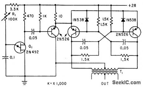
Transistor mvbr trigger for scr inverter is controlled by unijunction relaxation oscillator Q1. Squarewave output of T1 is required for triggering some inverter circuits.-D. V. Jones, Tum-Off Circuits for Controlled Rectifiers, Electronics, 33:32, p 52-55. (View)
View full Circuit Diagram | Comments | Reading(728)
THREE_STEP_SEQUENCE_TIMER
Published:2009/7/13 2:34:00 Author:May
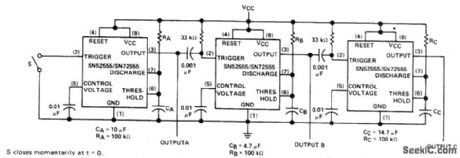
Provides three different outputs at predetermined time intervals for initializing conditions during startup or for activating test signals in sequence. Uses three Texas Instruments SN52555 or SN72555 timers which are interchangeable with other 555 timers. Values of R and C at output of each timer determine delays (T=1.1RC). With values shown below timers, output A is 5 V for interval of 1.1 s after switch is closed. At end of this interval, output B goes to 5 V for 0.5 s, after which output C goes to 5 V for 1.5 s to complete sequence. Supply can be 5-15 V.- The Linear and Interface Circuits Data Book for Design Engineers, Texas Instruments, Dallas, TX, 1973, p 7-53-7-61. (View)
View full Circuit Diagram | Comments | Reading(1480)
ROCKET_ROLL_CONTROL
Published:2009/7/13 2:31:00 Author:May
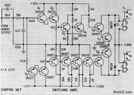
Signal from rollchannel demodulator is shaped for two-section switching amplifier that energizes roll jet relays.-R. E. King and H. Low, Solid-State Guidance For Able-Series Rockets, Electronics, 33:5, p60-63. (View)
View full Circuit Diagram | Comments | Reading(976)
PROXIMITY_CONTROL
Published:2009/7/13 2:27:00 Author:May
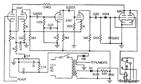
Gain of Hartley oscillator is set so oscillation is maintained only when Q of resonant circuit is normal. When ferrous or nonferrous materials come near pickup coil, Q is reduced, oscillation stops, and output tube conducts, to pull in relay for counting or for controlling industrial machinery. Can be set for operating range of from 1/8th inch to 1 foot.-D. Elam, Proximity Transducer Uses Rapid Relay, Electronics, 31:25, p73. (View)
View full Circuit Diagram | Comments | Reading(730)
| Pages:105/312 At 20101102103104105106107108109110111112113114115116117118119120Under 20 |
Circuit Categories
power supply circuit
Amplifier Circuit
Basic Circuit
LED and Light Circuit
Sensor Circuit
Signal Processing
Electrical Equipment Circuit
Control Circuit
Remote Control Circuit
A/D-D/A Converter Circuit
Audio Circuit
Measuring and Test Circuit
Communication Circuit
Computer-Related Circuit
555 Circuit
Automotive Circuit
Repairing Circuit