
Index 15
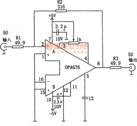
Broad Band Vedio Amplifier with 50Ω Input/Output Impedance (OPA676)
Published:2011/9/8 6:25:00 Author:Felicity | Keyword: Broad Band, Vedio Amplifier
View full Circuit Diagram | Comments | Reading(1024)
Underarm odor therapeutic apparatus circuit diagram
Published:2011/9/8 3:23:00 Author:Lucas | Keyword: Underarm odor, therapeutic apparatus
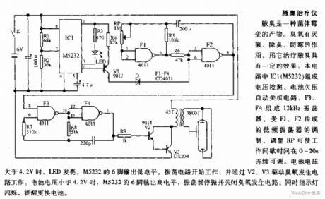
Underarm odor is a product of bacterial mildew. Ozone has the functions of sterilization, anti-odor, anti-mold and anti-mildew, and it has some specific treatment effect for underarm odor. In the circuit, IC1 (M5232) forms the voltage detection, battery undervoltage auto shutdown circuit, and F3, F4 form the 12kHz oscillator, which is modulated by the low-frequency oscillator composed of F1, F2, and adjusting RP can make work interval be continuously adjustable at 0 ~ 20S. When the battery voltage is greater than 4.2V, LED is lit, and M5232's pin 6 outputs low, then the oscillator works to drive ozone circuit by V2, V3.
(View)
View full Circuit Diagram | Comments | Reading(1903)
Multi-color projector circuit diagram for nerve relaxation
Published:2011/9/8 3:37:00 Author:Lucas | Keyword: Multi-color projector , nerve relaxation
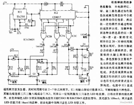
The circuit can mix red,green, blue in any color in nature by additive color mixing method or subtractive color mixing method, then they appears as the special viewing screen in a certain order. When your breath to see a variety of natural colors: red - yellow - green - green - blue - purple and the order changes in 20 to 30 seconds and repeats in the cycle, then your brain will automatically enter the hypnotic state, the tension of the brain is immediately relaxed. Multicolor projector is composed of the circuit which generates natural color changing order and multi-color viewing tube.
(View)
View full Circuit Diagram | Comments | Reading(2439)
Dual-output electronic ballast circuit diagram
Published:2011/9/7 22:19:00 Author:Lucas | Keyword: Dual-output electronic ballast
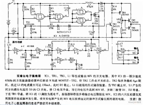
IC1, TR1, TR2, L1 form the switching power supply with output in 80V. One part of IC1 forms the 65kHz square wave oscillator to drive N-channel MOSFET-TR2 after buffering, then TR2 works in the switching state. During each 8μs turning time of TR2, L1's passing current is up to 150mA, at this time, D3 closes, and L1 stores energy in the magnetic field, when the TR2 stops, L1's induced current charges to C3 by the D3, then the C3 voltage increases. When its voltage rises to 80V, the zener diodes D1, D2 are conduction. So TR1 is turned on. Then IC1's pin 13 is in low level.
(View)
View full Circuit Diagram | Comments | Reading(2893)
The electronic thermometer circuit diagram for blind
Published:2011/9/8 2:57:00 Author:Lucas | Keyword: electronic thermometer, blind
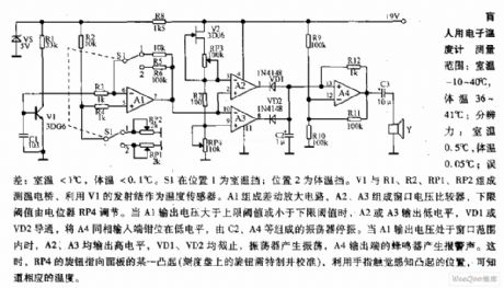
Measuring range: room temperature is -10 ~ 40 ℃; body temperature is 36 ~ 41 ℃; Resolution: room temperature is 0.5 ℃, body temperature is 0.05 ℃; error: room temperature <1 ℃, body temperature <0.1 ℃. When S1 is in position 1, it shows the room temperature profile; position 2 is the body temperature profile. V1, R1, R2, RP1, RP2 form the temperature testing bridge, which uses the V1 emitter junction as a temperature sensor. A1 forms the differential amplifier, and A2, A3 form the window voltage comparator, and the lower threshold is adjusted by the potentiometer RP4. When A1 output voltage is greater than the upper threshold or less than the lower threshold, A2 or A3 outputs low, VD1 or VD2 is conduction, then the inverting input of A4 is located in the embedded low level.
(View)
View full Circuit Diagram | Comments | Reading(2376)
Automatic voice greeting circuit diagram
Published:2011/9/7 1:56:00 Author:Lucas | Keyword: Automatic voice greeting
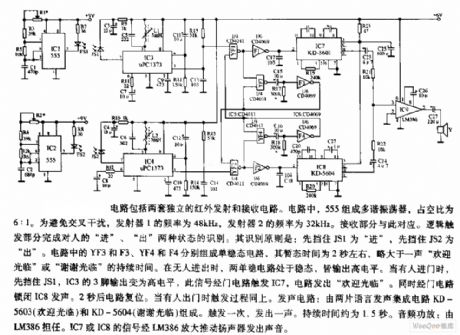
The circuit consists of two separate infrared transmitter and receiver circuits. In the circuit, 555 forms the multivibrator, and the duty cycle is 6:1. In order to avoid cross-infection, the frequency of the transmitter 1 is 48kHz, and the frequency of the transmitter 2 is 32kHz. Sound circuit consists of two voice integrated circuits KD5603 (Welcome) and KD-5604 (Thank you for coming). It is triggered once to emit sound. And the duration is 1.5 S. The audio amplifier is played by the LM386. IC7 and IC8's signal is amplified by LM386 to drive the speaker and emit sound.
(View)
View full Circuit Diagram | Comments | Reading(1261)
Wireless two-tone electronic doorbell circuit diagram
Published:2011/9/7 22:08:00 Author:Lucas | Keyword: Wireless two-tone, electronic doorbell
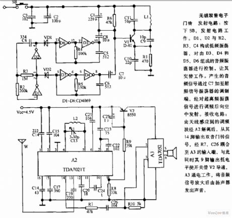
Transmitter: Pressing the SB will make the transmitter circuit work. D1, D2 and R2, R3, C4 constitute a low-frequency oscillator to control the audio oscillator composed of the D3, D4 and D5, D6, then it works alternately. The generated audio signal is added to modulation side of Rf signal oscillator by C7. Then high-frequency oscillator signal is sent to air after modulation. Receiver circuit: frequency-modulated wavesensed by the antenna is demodulated by A2, then its pin 14 outputs two-tone doorbell signal, which is coupled to the input of A3 by R7, C26, while the pin 9 outputs low so that switch V2 is conduction, then A3 gets power and works.
(View)
View full Circuit Diagram | Comments | Reading(5038)
Phone Flasher circuit diagram
Published:2011/9/6 3:55:00 Author:Lucas | Keyword: Phone Flasher
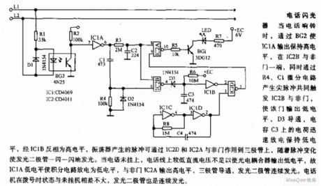
When the phone rings, the BG2 makes IC1A output high, and in one NAND gate end of IC2B, R4, C1 forms the differential circuit to generate spike pulse and trigger IC2B NAND gate, so that the gate outputs low, D3 is conduction , the charge on the capacitor C3 rapidly discharges and remains low, then it is in high level by IC1B inverter, and the oscillator pulse can be sent to the transistor by IC2D and IC2A NAND gates, and the LED flashes with the pulse changes. When the phone is not hung up, the DC voltage on telephone lines is not enough to make the optocoupler output low level.
(View)
View full Circuit Diagram | Comments | Reading(1462)
Voice electronic doorbell circuit diagram
Published:2011/9/6 3:44:00 Author:Lucas | Keyword: Voice electronic doorbell
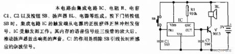
The circuit consists of integrated circuit IC, resistor R, capacitors C1, C2 and button SB, speaker BL, power supply and other components. When people press the doorbell button SB, IC is triggered to work. The memory voice signal is amplified by the transistor to promote the speaker and emit loud voice. C1 is used to eliminate the noise signal sensed by SB long lead.
(View)
View full Circuit Diagram | Comments | Reading(1428)
High pressure sodium lamp electronic ballast circuit diagram
Published:2011/9/5 3:35:00 Author:Lucas | Keyword: High pressure , sodium lamp , electronic ballast
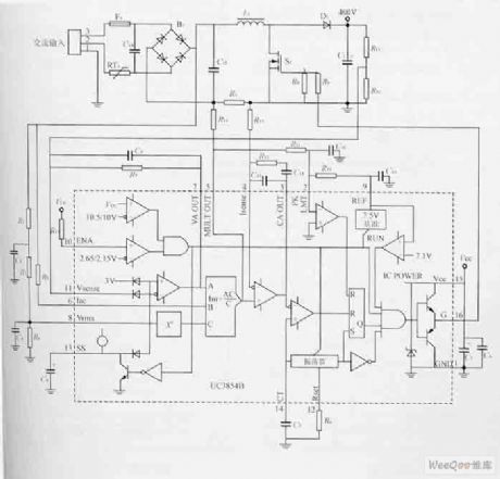
The circuit uses UC3854B as the control chip to establish an active power factor correction circuit with fixed frequency average current-mode, and the circuit is shown as the figure. In the figure, rectifier bridge B1, inductor L1, power switching device S1, boost diode D1, output filter capacitor C1 and resistor R1 form a current sampling PFC circuit. UC3854B provides all the active power factor correction features, which include voltage amplifier, analog multiplier / divider, current amplifier and a fixed frequency PWM, in addition, they also contain power MOSFET gate driver, 7.5V reference voltage, bus predictor, and over-current comparator.
(View)
View full Circuit Diagram | Comments | Reading(3334)
Electronic ballast circuit diagram for fluoresent lamp
Published:2011/8/29 3:15:00 Author:Lucas | Keyword: Electronic ballast , fluoresent lamp
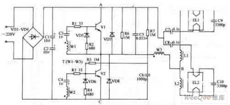
The electronic ballast circuit for fluorescent lamp is composed of the rectifier filter circuit, high-frequency oscillator circuit and output circuit. In the circuit, the rectifier filter circuit consists of the rectifier diodes VD1- VD4 and filter capacitors C1, C2; high-frequency oscillator consists of the transistors vi, V2, resistors R1-R7, capacitors C3, C4, C6, diodes VD5- VD8 and high frequency transformer T (W1-W3 are wound on the same magnetic ring to form a high-frequency transformer); output circuit is composed of the chokes L1, L2 and capacitors C1-C10.
(View)
View full Circuit Diagram | Comments | Reading(3693)
LED flashlight circuit
Published:2011/8/25 21:20:00 Author:chopper | Keyword: LED, flashlight circuit
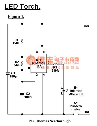
7555 time-based IC(can not use normal 555) is the core of a LED flashlight.A white light-emitting diode (if you can not find one, just take other colors) is issued about 400mcd brightness when it works, so that when it focuses, it can illuminate objects in 30 meters. The approach to focus is to install a short focal length focusing lens in front of LED . If you want to use other voltage values, the value of resistor R3 must be modified: 9V - 470 Ω 12V - 560 Ω (View)
View full Circuit Diagram | Comments | Reading(2662)
Automatic refrigerator protector
Published:2011/8/26 3:20:00 Author:Jessie | Keyword: refrigerator, protector
The automatic refrigerator protection line is simple with full function, reliable sensitive action, and it is useful accessory for refrigerator. When the 220V mains voltage is too low, the refrigerator motor may be damaged, R1 and RP1 partial pressure value decreases, so VD5 is conduction, then the integrated circuit IC turns on, VD7 stops, so the two-way thyristor VS is cut off, thereby the power of refrigerators cut off. RP1 can be set to adjust the undervoltage protection value. When the voltage is too high, it is possible to make the refrigerator motor overheating. RP2 can be set to adjust over-voltage protection value.
(View)
View full Circuit Diagram | Comments | Reading(1244)
Proportional derivative regulator D furnace circuit
Published:2011/8/26 2:33:00 Author:Jessie | Keyword: Proportional derivative regulator, D furnace circuit
This circuit has nothing to do with heating speed, the water temperature can be limited in given value. The operational amplifier connectedas thederivative regulator will output voltage whichis related to heating speed, and it is sentto in-phase inputof the switch amplifier by the transistor, then thereversed-phase is connected the thermistor. The higher the heating temperature is, theearlier the cut of the heater.
The maximum current of relay circuit is 70mA, which can determine the required operating voltage.
(View)
View full Circuit Diagram | Comments | Reading(933)
POKO TD-169C Hair dryer circuit diagram
Published:2011/8/19 1:15:00 Author:Jessie | Keyword: Hair dryer, POKO
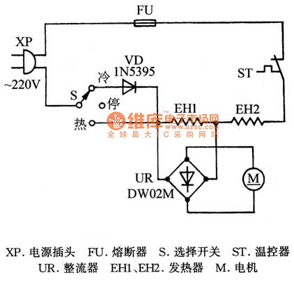
XP-plug; FU-fuse; ST-temperature controller; UR-rectifier; S-selection switch; M-motor; EH1,EH2-heater. (View)
View full Circuit Diagram | Comments | Reading(10307)
PT2262/PT2272 Chip principle circuit diagram
Published:2011/8/18 1:20:00 Author:Jessie | Keyword: Chip principle
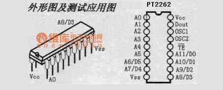
Application scope: vehicle anti-theft system, family security system, remote control toys, other appliances' remote controlling.
(View)
View full Circuit Diagram | Comments | Reading(2469)
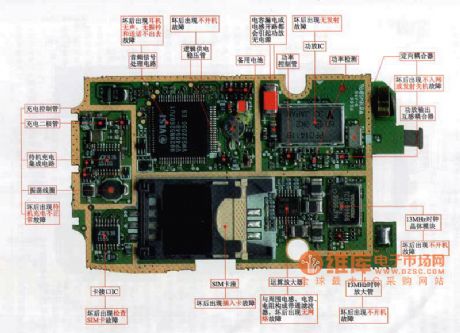
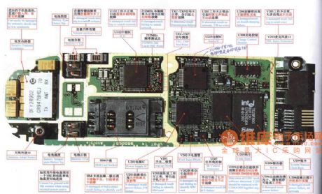
Samsung 800 mobile phone maintenance circuit diagram
Published:2011/8/18 0:57:00 Author:Jessie | Keyword: mobile phone maintenance, Samsung
View full Circuit Diagram | Comments | Reading(5323)
Ericsson T18 mobile phone maintenance circuit diagram
Published:2011/8/18 0:57:00 Author:Jessie | Keyword: mobile phone maintenance, Ericsson
View full Circuit Diagram | Comments | Reading(3142)
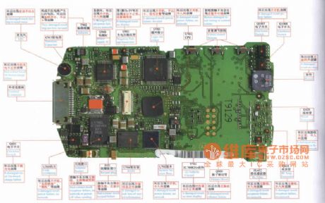
Nokia 5110/6110 mobile phone maintenance circuit diagram
Published:2011/8/17 21:51:00 Author:Jessie | Keyword: mobile phone maintenance
View full Circuit Diagram | Comments | Reading(6486)
MOTOROLA 338 mobile phone maintenance circuit diagram
Published:2011/8/17 21:52:00 Author:Jessie | Keyword: mobile phone maintenance
View full Circuit Diagram | Comments | Reading(2888)
| Pages:15/126 1234567891011121314151617181920Under 20 |
Circuit Categories
power supply circuit
Amplifier Circuit
Basic Circuit
LED and Light Circuit
Sensor Circuit
Signal Processing
Electrical Equipment Circuit
Control Circuit
Remote Control Circuit
A/D-D/A Converter Circuit
Audio Circuit
Measuring and Test Circuit
Communication Circuit
Computer-Related Circuit
555 Circuit
Automotive Circuit
Repairing Circuit