
Index 6
Automatic series reactance starting three-phase motor 1
Published:2012/9/12 2:03:00 Author:Ecco | Keyword: Automatic series, reactance starting, three-phase motor
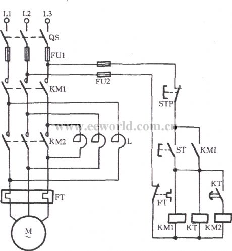
As shown in the diagram, thecircuituses time relay KTto realizeautomatic shorting reactor without pressing operation buttonby handsin the switching process of startup and operation.
(View)
View full Circuit Diagram | Comments | Reading(2387)
Tone Doorbell circuit
Published:2012/9/11 21:14:00 Author:Ecco | Keyword: Tone Doorbell
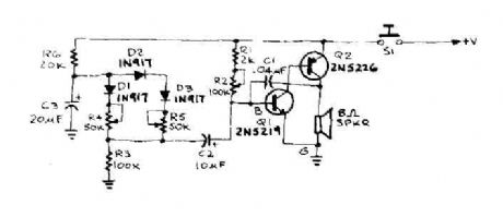
When the door is pushed, you hear a whisper that slide up to a higher frequency. The oscillator frequency is determined by AF coupling capacitance, C 1 and the value of the resistor connected between the base of IQ and the earth. This resistance, RBG is equal to (Ri + R2) RJ. First, suppose that 51 is closed and R2 have been adjusted to produce a pleasant, low frequency tone. The capacitor C3 charges through R6 until it reaches such a tension that will cause diode Dl to conduct. (View)
View full Circuit Diagram | Comments | Reading(1265)
Bell circuit with two 555 timers
Published:2012/9/11 20:20:00 Author:Ecco | Keyword: Bell, two 555 timers
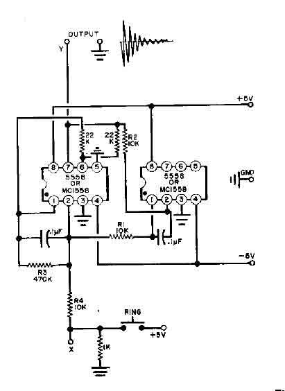
This simple Bell circuit uses two 555 timers. The frequency is controlled by the capacitors that must be preserved almost identical in value to each other for best results. Fine tuning is done with R1 and R2. (View)
View full Circuit Diagram | Comments | Reading(1446)
Automatic audio fader circuit
Published:2012/9/10 20:55:00 Author:Ecco | Keyword: Automatic, audio fader
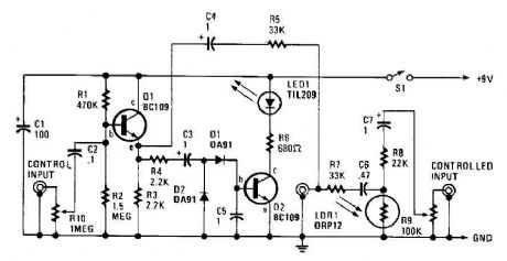
The automatic fader drops at the background music while the narration is in place. The control input through RIO, a preset audio level control, into an emitter-follower buffer stage CQI). The buffer provides high input impedance and ensures that the source impedance is low enough to drive the rectifier and smoothing circuit, consisting of DI, D2, and C5. The smoothed output drives a simple LED circuit. LD and R8 form an IR input pad through which the output is fed through C6 and C7 to the output jack.
Source: discovercircuits (View)
View full Circuit Diagram | Comments | Reading(4251)
Door Knock Beeper -- June 14, 2009
Published:2012/9/6 20:12:00 Author:Ecco | Keyword: Door Knock , Beeper
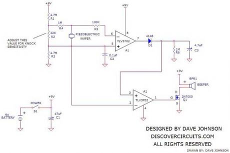
In some apartment buildings and homes, not equipped with a door bell, it may be hard to hear someone knocking on the front door. The circuit below provides a means to activate a loud beeping sound inside, whenever someone knocks on the door from the outside. The circuit is powered by a 9v battery, which should provide years of service. An on/off switch allows the device to be turned off if desired. It is suggested that the circuit be housed in a plastic box with a 9v battery holder. A Serpac box from Mouser, part number 635-211-I-G is just right for this application. It is about 4 inches long and 2.6 inches wide. It has a nice compartment for a 9v battery.
Source: discovercircuits (View)
View full Circuit Diagram | Comments | Reading(1465)
Star Trek Doorbell
Published:2012/9/5 20:56:00 Author:Ecco | Keyword: Star, Trek Doorbell
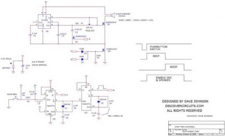
In the Star Trek ?Next Generation? TV series, the doorbell outside the private quarters of a crew member makes a particular ?beep-boop? sound. The 3v battery powered circuit below tries to simulate this sound. The circuit uses one 74HCT74 dual D flip/flop IC, wired as two one-shot circuits. Both are designed to produce a pulse about one half second long. The first pulse turns on a 555 timer to form the beep sound.
Source: discovercircuits (View)
View full Circuit Diagram | Comments | Reading(2020)
AC Current Controls Hour Meter
Published:2012/9/5 20:36:00 Author:Ecco | Keyword: AC Current, Controls , Hour Meter

Many systems require routine maintenance based on machine operation time. The circuit below is a simple way to turn on a hour meter whenever AC power is supplied to the machine. An inexpensive snap-on current transformer from Magnetics Inc, is used to detect the AC current.
Source: discovercircuits (View)
View full Circuit Diagram | Comments | Reading(3121)
Basement Doorbell
Published:2012/9/4 20:22:00 Author:Ecco | Keyword: Basement Doorbell

This circuit will activate a beeper in the basement, whenever the front doorbell is pressed.
Source: discovercircuits (View)
View full Circuit Diagram | Comments | Reading(978)
Low Power Under- and Over-Voltage Monitor
Published:2012/9/3 3:03:00 Author:Ecco | Keyword: Low Power, Under-voltage , Over-Voltage, Monitor
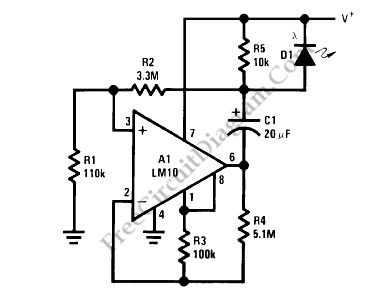
This voltage monitor has two threshold, VTH for undervoltage and VTH’ for overvoltage. Using the component values shown in the schematic diagram below, this circuit give 6V for VTH and 15V for VTH1. Above 6V, the LED indicator of this voltage monitor circuit will increase the flash rate until reach 15V. This circuit will stop flashing at voltage below 6V and above 15 volts since there will be no current flowing through C1. At threshold boundary, the output of LM10 will saturate to negative below VTH and saturate to positive above VTH’.
To customize circuit we can select the resistors values according to chosen VTH and VTH’ using the following formula:
VTH=[R4(R1+R2)Vref]/[R1(R3+R4)];
VTH’=[R4(R1+R2)Vref]/[R1(R3+R4)-R3(R1+R2)]
Since the current consumption is very small (around 500uA), this voltage monitor will be suitable for various application demanding low cost solution, such as battery monitoring, small testing equipments, or power line indication.(Source: freecircuitdiagram)
(View)
View full Circuit Diagram | Comments | Reading(2)
Heartbeat Sensor (Tranduscer)
Published:2012/9/3 2:00:00 Author:Ecco | Keyword: Heartbeat Sensor, Tranduscer
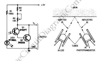
To build a heart-beat transducer not as difficult as imagined. Circuit below shows a simple heart-beat transducer.
This circuit made from an infrared phototransistor and infrared LED. This transducer works with the principle of light reflection,in this case the light is infrared. The skin is used as a reflective surface for infrared light. The density of blood in the skin will affect on the IR reflectivity. The pumping action of heart causes the blood density rises and falls. So that we can calculate the heart rate based on the rise and fall of intensity of infrared that reflected by skin.
Source: freecircuitdiagram
(View)
View full Circuit Diagram | Comments | Reading(2378)
Simple Lie Detector
Published:2012/9/3 1:58:00 Author:Ecco | Keyword: Simple , Lie Detector

Source: freecircuitdiagram
To know someone is lying or not we can use lie detector. This is a simple lie detector that can be made in minutes. It works to detect the someone who telling lie but it is not as sophisticated as the ones the professionals use. Here is the schematic diagram of this circuit:
The skin resistance will go down when someone telling lie and this circuit works by measuring it. We can use electrode pads, alligator clips, or just wires and tape as the electrodes. We have to adjust R2 to position the meter at the center at the beginning of the interrogation (relax condition), then we can know someone is lying when the meter changes in response to a question.
(View)
View full Circuit Diagram | Comments | Reading(0)
Single Cell 1.5V Hearing Aid
Published:2012/9/3 1:57:00 Author:Ecco | Keyword: Single Cell , 1.5V, Hearing Aid

Source: freecircuitdiagram
This circuit can be assembled in a small board, or you can even do it without board. To assemble without board, you can connect every component leads each other and solder them. Align the component bodies and their leads to avoid shorts, secure with insulation tape, glue, or resin.
This is a hearing aid circuit with 1.5v supply. This circuit is used to detect very faint sounds, then deliver the sounds to an 8 ohm earpiece. This circuit requires 1.5v input voltage, need only a single cell battery. Here is the schematic diagram of the circuit:
(View)
View full Circuit Diagram | Comments | Reading(4095)
An experimental crystal oscillator FM transmitter circuit
Published:2012/8/27 22:46:00 Author:Ecco | Keyword: experimental , crystal oscillator , FM transmitter
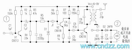
As shown in Figure 1, V1 and related resistive and capacitive components form the first level audio amplifier circuit which provides sufficient strength audio signals for modulating level. D1 is variable capacitance diode, and its equivalent capacitance varies with the reverse voltage on two poles, thus enabling center frequency of oscillator composed of crystal oscillator and external circuit change to achieve the purpose of FM. The signal output by oscillator is frequency doubled, amplified by the V3, then it is output by the tuned transformer after completing matching and filtering. The circuit uses tuned transformer, so it needs to restructure their cores after finished making. Its method is to produce a simple field strength circuit (as shown in Figure 2) to connect with the output terminal of the transformer, then adjusting the magnetic core until the ammeter indicating the maximum value.
(View)
View full Circuit Diagram | Comments | Reading(6663)
Wireless responder circuit with transceiver and codecs module
Published:2012/8/26 21:40:00 Author:Ecco | Keyword: Wireless responder , transceiver , codecs module
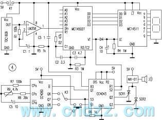
Transmitter circuit is mainly composed of radio transmission header TDC1808 and dedicated coding integrated circuit MC145026, and it is shown in Figure 1. MC145026 encoding manifold's pin function is shown in Figure 2. It consists of the clock oscillator, divider, address/data-encoding input circuit and data selection and buffer. Clock oscillator and divider provide benchmark clock for the whole encoder to coordinate the work of other parts. Address/data-encoding input circuit will enter different addresses and encoding signals converted from data. Data selection and buffer circuit can change parallel code to a serial code and output.
(View)
View full Circuit Diagram | Comments | Reading(1987)
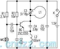
1.5V miniature wireless FM microphone circuit
Published:2012/8/26 21:03:00 Author:Ecco | Keyword: 1.5V, miniature , wireless , FM microphone
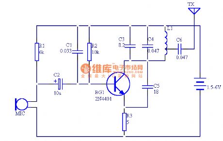
The circuit shown in this paper uses 12 components to form a miniature wireless FM microphone with stable operating frequency, and its transmitting distance is about 30 meters and more than 100 meters at 6V power supply.The circuit is shown as Figure, BG1, C1 and C3 form a high - frequency oscillation circuit. The transmitting distance is related to the current of the launch tube, and the upward bias resistor R2 can change BG1 output current.If you select BG1, tube's fT must be greater than 300MHz, but if the fT is too high, it will affect modulation. Inductance L uses two coils to make wound, but the wound must be the same, L1 uses 0.5mm enameled wire with 4 turns in a diameter of around 5mm-diameter skeleton, L2 has 3 turns. The antenna can be made by a soft wire with 0.6 meters length.
(View)
View full Circuit Diagram | Comments | Reading(7346)
Ultrasonic Insect Killer
Published:2012/8/21 21:31:00 Author:Ecco | Keyword: Ultrasonic Insect Killer
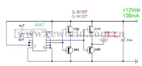
This is a very simple ultrasonic mosquito, insects, cockroaches repellercircuit.The circuit is a relaxation oscillation circuit which iscomposed of the CMOS 4047 monoflop, adjusting 4K7 can makeits center frequencybe approximately 22KHz, four transistors form bridge power output to promote the 3.25 inch Piezo and emit ultrasonic signals.
(View)
View full Circuit Diagram | Comments | Reading(4256)
Automobile AM radio circuit
Published:2012/8/20 22:29:00 Author:Ecco | Keyword: Automobile, AM radio
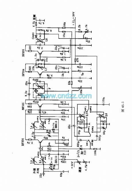
This circuit shows the high and mid part of car radio, and the medium wave band I is 520 ~ 950kHz, Poland II is 900 ~ 1640kHz. Loop tuning uses tunable diode BB113.Main coil data:L1: 122 turns; L2: 122 turns ; L3: 68 turns ; L5: 96 turns ( coupling coil with 7 turns ); L6: 64 turns ( coupling coil with 5 turns) . L1 ~ L6 use 8 × 0.03 copper.L7: 90 turns, 6 × 0.04 copper.L8: 120 turns ( coupling coil with 60 turns ), 8 × 0.03 copper.F: 95 turns ( coupling coil with 5 turns ), 8 × 0.04 copper.
(View)
View full Circuit Diagram | Comments | Reading(2456)
Radio circuit with quartz crystal oscillator
Published:2012/8/21 1:07:00 Author:Ecco | Keyword: Radio , quartz crystal, oscillator
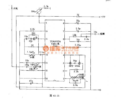
The circuit's frequency can be to 27MHz. Intermediate frequency is 455kHz. In order to increase the receive frequency, it uses the pre-stage of the field effect transistor.
(View)
View full Circuit Diagram | Comments | Reading(1839)
Highly sensitive wireless Snoop device circuit
Published:2012/8/20 23:05:00 Author:Ecco | Keyword: Highly sensitive , wireless , Snoop device
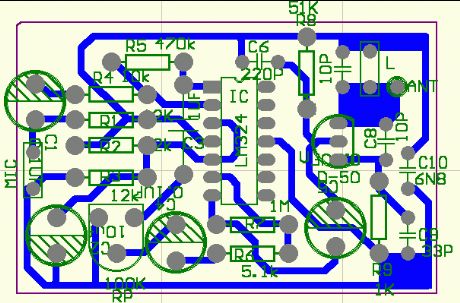
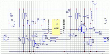
The circuit is shown in the figure, it is composed of highly sensitive microphone amplifier and wireless transmitter unit, and the amplifier consisits of two op amps in quad op amp integrated circuit LM324. When the electret microphone MIC picks up weak sound signal, it will generate a signal voltage across the MIC, then the signal is amplified by pin 3 of the first stage operational amplifier after being coupled by capacitor C1, its amplification gain is more than 20 decibels, after the first-stage coupling, it is output from pin 1 and coupled by capacitor C3, then potentiometer RP control it for the second-stage amplifier by pin 5, then weak voice signal is amplified to have sufficient magnitude and sent to high - frequency transmitting circuit by coupling with C5.
(View)
View full Circuit Diagram | Comments | Reading(4246)
Simple long-distance wireless FM microphone circuit
Published:2012/8/21 1:29:00 Author:Ecco | Keyword: Simple, long-distance, wireless , FM microphone
The the loop antenna L1 for emission also serves as the oscillation coil, the high-frequency current flowing in antenna is synchronized resonance with the oscillation frequency, so it is always in the best emission state. Accoring to practice, launching distance is about 100 ~ 150m in empty mine. In contrast, in the case of equal working voltage, current and emission frequency, L1 is replaced by ordinary spiral coil, the oscillation transistor collector is connected to a 5pF capacitor and 0.8m Rod antenna for emission experiments, the two the transmitting distancea are almost equal. So it proves that the concealed loop antenna( it doubles the oscillator coil) has high emission efficiency.
(View)
View full Circuit Diagram | Comments | Reading(2940)
| Pages:6/126 1234567891011121314151617181920Under 20 |
Circuit Categories
power supply circuit
Amplifier Circuit
Basic Circuit
LED and Light Circuit
Sensor Circuit
Signal Processing
Electrical Equipment Circuit
Control Circuit
Remote Control Circuit
A/D-D/A Converter Circuit
Audio Circuit
Measuring and Test Circuit
Communication Circuit
Computer-Related Circuit
555 Circuit
Automotive Circuit
Repairing Circuit