
Switching-Regulator Circuit
Index 2
The auto control energy saving lamp circuit composed of solar battery
Published:2011/7/20 20:48:00 Author:Borg | Keyword: energy saving lamp, solar battery
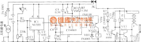
See as the figure, the solar auto control energy saving lamp circuit consists of the solar cell charger, light control switch, timing switch and reversing circuit. To light the energy-saveing lamp, both the light control and timing switches are connected. At daytime, the sunlight is shed on the solar cell board, which converts the light power into electricity and charges the storage cell with the help of the diode VD1. (View)
View full Circuit Diagram | Comments | Reading(1639)
μPC1099 switching power supply circuit
Published:2011/7/11 2:34:00 Author:chopper | Keyword: switching, power supply circuit
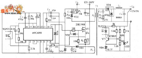
Figure shows the pPC1099 switching power supply.μPC1099 is the switching power supply integrated controller in PWM mode.And it is applied to the primary side control circuit whose main switching components adopt power MOSFET,and the main features are that:it can directly drive the power MOSFET; it is the totem-pole output circuit whose peak output current is 1.2A;it has the fast current of high-impedance;it is the over-current limiting circuit;its oscillation frequency is 50~500kHz;it has the over-voltage protection function and remote control;it uses ⑩-pin DIP and SOP packages.
(View)
View full Circuit Diagram | Comments | Reading(2096)
Push-pull converter switching power supply circuit diagram
Published:2011/5/5 7:08:00 Author:Nicole | Keyword: switching power supply, push-pull converter
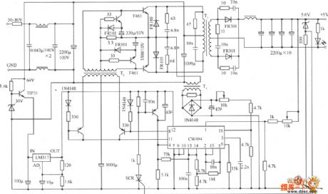
Push-pull converter switching power supply circuit. CW494 is a double-ended converter modulator integrated circuits, including error amplifier, voltage reference, clock oscillator, pulse width modulator and other circuits. Transformer T1 is a high-frequency transformer which can transferenergy to the load. T2 is incentive to promote the transformer. It can transmit the two series of drive pulse produced by the CW494 pulse modular to the drive and switch base of the push-pull circuit after amplfied by the driver transistor. L is the transformer windings on the pulse of the sample through the transformer and rectifier AC voltage, the resistance of the sample sent to the pulse modulation circuit CW494 16 feet, as the error amplifier inverting input. The power transistor of this power supply uses F461fast series. Where the voltage feedback, input and output are directly connected. If the input and output need to be isolated, the optocoupler can be used.
(View)
View full Circuit Diagram | Comments | Reading(5101)
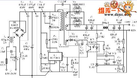
35w set -top -box switching supply circuit diagram
Published:2011/5/11 4:16:00 Author:Ecco | Keyword: 35w supply , set -top -box switching
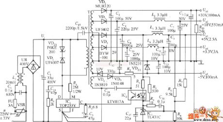
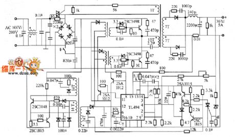
The 5 roads voltage of 35w set -top -box switching supply circuit diagram are distinguished as: Uo1(+30 V, 100 ma), Uo2(+18 V, 550 ma), Uo3(+5 V, 2.5 A), Uo4(+3.3 V, 3 A), Uo5.(-5 V, 100 ma). Among them, +5 V and + 3.3 Vare main output, the rest of allare assisting output. When the swaping input voltage u=220(1 ± 15%) V, the total output power ofswitch reaches 38.5 W, if adopting breadth range voltage input(u=85~265 V), the total outputreduces 25 W. It can be used as the power supply of box(Set ― top Box), video recorder(VCR) , shoot video recorder(CVCR) and DVD machine. The power supply of machine set -top -box switching is higher than 77%, and it has the function of undervoltage and overvoltage protection. (View)
View full Circuit Diagram | Comments | Reading(5631)
Micro Controller MC9S08AW32 and HT1621 Interface Circuit
Published:2011/6/15 8:16:00 Author:Michel | Keyword: Micro Controller, Interface Circuit

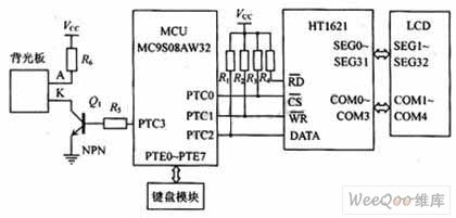
Liquid crystal display system hardware interface circuit mainly contains micro controller,MC9S08AW32, liquid crystal display module LCD, backlight,liquid crystal drive chip HT1621,key module and resistance and capacitance components etc. and it is showed as the figure 1.
In the figure 1, PTC0 ~ PTC2 port of micro controller MC9S08AW32 are connected to liquid crystal drive chip HT1621's chip selecting signal port (CS), write signal control port (WR) and data signals port (DATA)respectively and they connect pull-up resistors to high PWL respectively. Read signal control port (RD) only needs to connect to high PWL via pull-up resistors because there is no necessary to use HT1621's Read operation.The MC9S08AW32 PTE0 ~ PTE7 port connects key module, PTC3 port connects NPN transistor, which is to control back panels. (View)
View full Circuit Diagram | Comments | Reading(3290)
FA550O switching power supply circuit
Published:2011/7/9 3:26:00 Author:chopper | Keyword: switching, power supply circuit
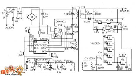
Figure shows the FA550O switching power supply,its input AC voltage is 100V, output is 16V/2.5A. FA5500 is a integrated controller, its output OUT (pin ⑦) drives grid of power M0S-FET (VF1) through the resistor R2.R3 and R14are the over-current detection resistors for VF1.VF1 undertakes switch work,making the winding N1 of transformer T1 through the pulse current.C3 is the resonant capacitor, C4 is the the capacitor in order to reduce the output impedance.Theoutput voltage of winding is converted into output DC voltage after it is commutated and smoothed by VD10 and C5.
(View)
View full Circuit Diagram | Comments | Reading(1103)
Small power switching power supply circuit with 5V/0.4A output
Published:2011/7/9 3:29:00 Author:chopper | Keyword: Small power, switching, power supply, 5V/0.4A output
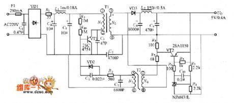
The picture shows the small power switching power supply circuit with 5V/0.4A output.The circuit adopts saturable transformer to gain the soft switch work.
(View)
View full Circuit Diagram | Comments | Reading(3593)
soft switching power supply circuit with fixed frequency
Published:2011/7/9 3:44:00 Author:chopper | Keyword: soft switching, power supply, fixed frequency
The soft switching power supply circuit with fixed frequency is shown as picture
(View)
View full Circuit Diagram | Comments | Reading(1354)
Fixed frequency common switching power supply circuit with PWM integrated controller
Published:2011/7/9 3:43:00 Author:chopper | Keyword: Fixed frequency, common, switching, power supply, PWM, integrated controller
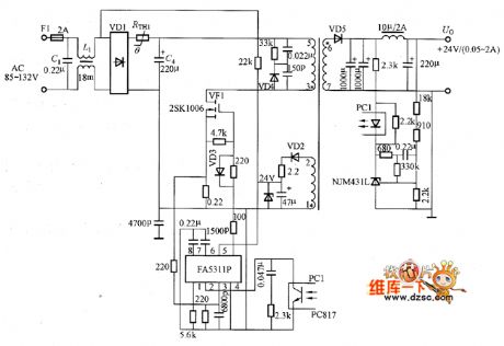
Fixed frequency common switching power supply circuit with PWM integrated controller is shown as picture
(View)
View full Circuit Diagram | Comments | Reading(1241)
ZCS switching power supply circuit of NE555
Published:2011/7/8 20:44:00 Author:chopper | Keyword: ZCS, switching, power supply
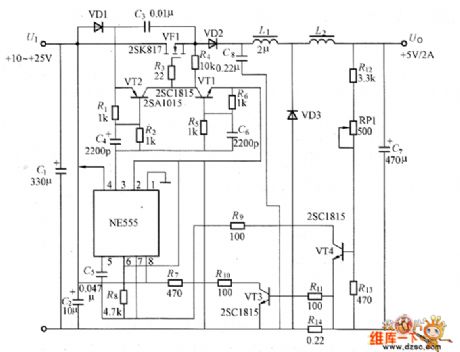
The picture shows the ZCS switching power supply circuit of NE555.This is the current resonance method(ZCS) switching power supply which is formed by adding LC series resonant circuit to step-down DC-DC converter.ZCS mode adopts fixed conduction time of resonant cycle-time to change frequency modulation.In the circuit, NE555 forms the common step-down DC-DC converter composed of voltage-controlled oscillators,switching power MOSFET (VF1),freewheeling diode YD3,smoothing inductor L2 and so on.Inductor L1, capacitor C2 constitute a resonant circuit. (View)
View full Circuit Diagram | Comments | Reading(3501)
MA6540 switching power supply circuit
Published:2011/7/9 3:47:00 Author:chopper | Keyword: switching, power supply circuit
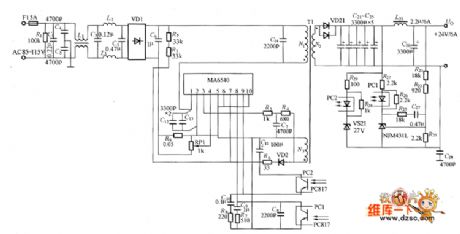
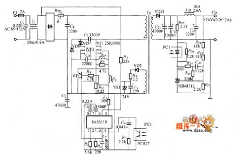
Figure shows the MA6540 switching power supply circuit,the output voltage is 24V,output current is 6A.MA6540 is the IC of excited power MOSFET with part resonance function.
(View)
View full Circuit Diagram | Comments | Reading(2806)
low noise, efficient switching power supply circuit
Published:2011/7/9 3:40:00 Author:chopper | Keyword: low noise, efficient, switching, power supply circuit
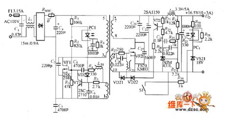
The low noise, efficient switching power supply examples composed of soft switching circuit and synchronous rectification circuit is shown as picture.Power supply output is 16.5V/3A,conversion efficiency is 88%. Although this power is designed for 16.5V voltage laptops,you can make the output voltage between 3.3 ~ 20V through changing the secondary winding turns of transformer and other component parameters like R, C.If VT1 selects 100V voltage device, the output voltage can reach 30V. The efficiency will be 82% when output is 5V,and efficiency will be 90% when output is 30V.
(View)
View full Circuit Diagram | Comments | Reading(3541)
Half-bridge practical switching power supply circuit
Published:2011/7/10 2:39:00 Author:chopper | Keyword: Half-bridge, practical, switching, power supply circuit
Half-bridge practical switching power supply circuitis shown as picture
(View)
View full Circuit Diagram | Comments | Reading(4150)
RCC practical switching regulator circuit
Published:2011/7/10 3:06:00 Author:chopper | Keyword: RCC, practical, switching regulator circuit
RCC practical switching regulator circuit is shown as picture
(View)
View full Circuit Diagram | Comments | Reading(1646)
internal equivalent circuit of HA17385 switching power supply integrated controller
Published:2011/7/10 6:17:00 Author:chopper | Keyword: internal, equivalent, switching power supply, integrated controller
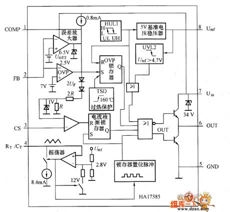
HA17385 switching power supply integrated controller uses ⑧-pin DIP package,the figure shows the internal equivalent circuit.From the equivalent circuit,we can learn that HA17385 chip includes all circuits composed of switching power supply like 5V reference voltage regulator, oscillator (triangle wave generator), the error amplifier and power MOSFET drive circuit.The maximum duty ratio of PWM wave is determined by the resistor and capacitor connected to RT/CT end of oscillator.
(View)
View full Circuit Diagram | Comments | Reading(1089)
HA17385 switching power supply with constant power
Published:2011/7/10 6:06:00 Author:chopper | Keyword: switching power supply, constant power
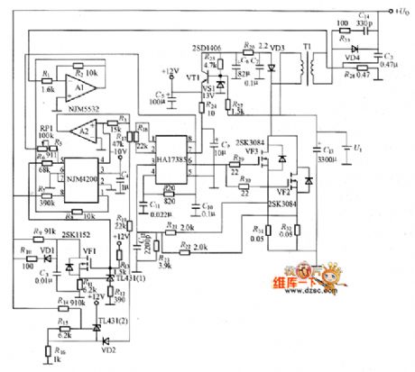
Figure shows HA17385 switching power supply with constant power,its output voltage is 85V (380V for no-load),output power is 35W, input voltage is 10~16V, and the maximum output current is about 0.5A.This constant switching power supply can be used for sputtering discharge,welding discharge systems and ballast which can inhibit radiation intensity of high-pressure mercury lamp.Circuit adopts on/off work method,the output power can be adjusted by RP1.
(View)
View full Circuit Diagram | Comments | Reading(1350)
DC / DC converter 250W switching power supply circuit diagram composed of TOP249Y
Published:2011/6/30 3:05:00 Author:Ecco | Keyword: DC / DC , converter, 250W , switching power supply
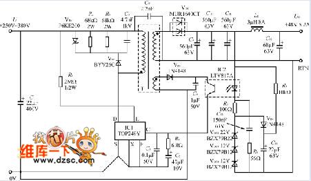
The DC / DC converter switching power supply uses a TOP249Y with input 250V ~ 380V DC, and the output is 48V, 5.2A (250W), then the power efficiency is up to 84%. The circuit is shown in Figure 2. High-frequency filter capacitor C1 is specifically inhibit the input from the electromagnetic interference. As the TOP249 works in its power limit, which need short connect X-side and the source S, within the limit is set the maximum current, that is ILIMIT = ILIMIT (max) = 5.7A.
(View)
View full Circuit Diagram | Comments | Reading(6960)
Limited current circuit with transistor
Published:2011/6/27 21:44:00 Author:chopper | Keyword: Limited current circuit, transistor
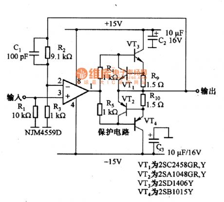
The picture is a limited current circuit with operational amplifier.In the circuit,R9 and R10 are used to detect output current.When the voltage drop is more than 0.6V,VT1 and VT2 will stop to cut off current.In this case,the current of VT3 and VT4 is limited within 400mA. (View)
View full Circuit Diagram | Comments | Reading(1475)
STR-S6709 switch power supply thick film integrated circuit
Published:2011/6/15 8:05:00 Author:chopper | Keyword: switch power supply, thick film, integrated circuit
STRS6709 is a PWN control integrated circuit of current mode,and it is applie (View)
View full Circuit Diagram | Comments | Reading(1385)
High-efficiency 70W universal switching power supply module circuit diagram
Published:2011/6/27 4:03:00 Author:Ecco | Keyword: High-efficiency , 70W , universal , switching power supply , module
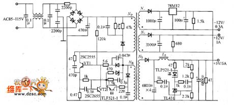
TOPSwitch GX is suitable for making low-cost, high efficiency, small size, full-enclosed switching power supply module or power adapter (adapter). When the ambient temperature does not exceed 40 ℃, the module can be reduced to the dimensions of 10.5mm × 5.5mm × 2.5mm. The AC input voltage range is 85V ~ 265V, which is a common worldwide voltage range. Rated output power is PO = 70W; load regulation is SI = ± 4%; power efficiency is η ≥ 84% (when the AC input voltage U = 85V, full load efficiency is 85%; when U = 230V, the power efficiency is up to 90% ); load power consumption is <0.52W (U = 230V pm).
(View)
View full Circuit Diagram | Comments | Reading(6512)
| Pages:2/8 12345678 |
Circuit Categories
power supply circuit
Amplifier Circuit
Basic Circuit
LED and Light Circuit
Sensor Circuit
Signal Processing
Electrical Equipment Circuit
Control Circuit
Remote Control Circuit
A/D-D/A Converter Circuit
Audio Circuit
Measuring and Test Circuit
Communication Circuit
Computer-Related Circuit
555 Circuit
Automotive Circuit
Repairing Circuit