
Basic Circuit
Index 12
Lighting LED constant current source driver circuit diagram
Published:2013/12/17 2:26:00 Author: | Keyword: Lighting LED constant current source driver circuit diagram,
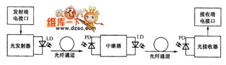

Using this kind of drive circuit, LED directly by the constant current source supply, no feedback, also do not need to compensate, principle as shown in figure 1
Figure 1 LED constant current source driver design
In this circuit, the bias voltage source will be poor stability, large ripple coefficient of external power input into stable constant voltage output, a constant voltage will serve as the input of voltage controlled current source, resulting in a stable and constant current output.
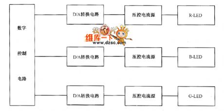
Constant current source driving scheme is often used in simple structure, no high requirements of LED lighting circuit or implement feedback difficult of the combined model of LED lighting circuit. For example, a red (R), green (G), blue (B) 3 kinds of color chip packaging in a pipe inside of three color leds. The RGB - LED according to the additive principle of light, when each color according to the variety of different numerical combination can realize the true color. Through which according to the LED luminous intensity is proportional to the size of the power flow of this feature, RGB three colors of the change of light intensity, set each color has a Nbit brightness, combine 3 Nbit color, can send out to suit the requirements of true color. As shown in figure 2.
Figure 2 tricolor LED driver design (View)
View full Circuit Diagram | Comments | Reading(1081)
Shanghai Excelle headlight and headlight adjustment circuit diagram
Published:2013/12/16 21:17:00 Author:lynne | Keyword: Shanghai Excelle headlight and headlight adjustment circuit diagram,
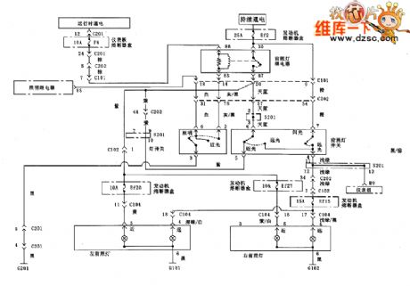
Shanghai Excelle headlight and headlight adjustment circuit diagram shown in Fig.:
(View)
View full Circuit Diagram | Comments | Reading(842)
Shanghai Excelle not closed headlight reminder buzzer circuit diagram
Published:2013/12/16 20:45:00 Author:lynne | Keyword: Shanghai Excelle not closed headlight reminder buzzer circuit diagram,
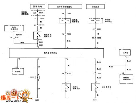
Shanghai Excelle not closed headlight reminder buzzer circuit diagram shown in Figure:
(View)
View full Circuit Diagram | Comments | Reading(869)
Shanghai Excelle reversing lamp circuit
Published:2013/12/16 20:47:00 Author:lynne | Keyword: Shanghai Excelle reversing lamp circuit,
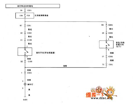
Shanghai Excelle reversing lamp circuit shown in Figure:
(View)
View full Circuit Diagram | Comments | Reading(757)
Shanghai Excelle sound system circuit
Published:2013/12/16 20:48:00 Author:lynne | Keyword: Shanghai Excelle sound system circuit,
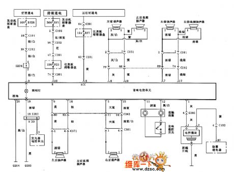
Shanghai Excelle sound system circuit shown in Figure:
(View)
View full Circuit Diagram | Comments | Reading(818)
Shanghai Excelle meter circuit
Published:2013/12/16 20:54:00 Author:lynne | Keyword: Shanghai Excelle meter circuit,
Shanghai Excelle meter circuit shown in Figure:
(View)
View full Circuit Diagram | Comments | Reading(814)
Defogger circuit
Published:2013/12/16 20:55:00 Author:lynne | Keyword: Defogger circuit,
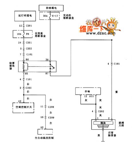
Defogger circuit shown in Figure:
(View)
View full Circuit Diagram | Comments | Reading(972)
Electric sunroof circuit
Published:2013/12/16 20:56:00 Author:lynne | Keyword: Electric sunroof circuit,
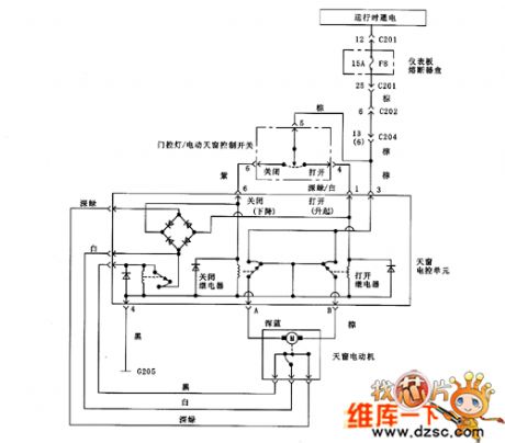
Electric sunroof circuit shown in Figure:
(View)
View full Circuit Diagram | Comments | Reading(1228)
Electronically controlled vehicle side mirror circuit schematics
Published:2013/12/16 20:58:00 Author:lynne | Keyword: Electronically controlled vehicle side mirror circuit schematics,
Electronically controlled vehicle side mirror circuit schematics as shown:
(View)
View full Circuit Diagram | Comments | Reading(916)
Automatic temperature control circuit
Published:2013/12/16 21:00:00 Author:lynne | Keyword: Automatic temperature control circuit,
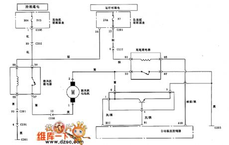
Automatic temperature control circuit shown in Fig.:
(View)
View full Circuit Diagram | Comments | Reading(886)
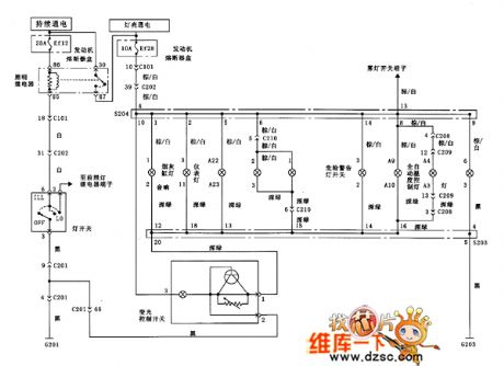
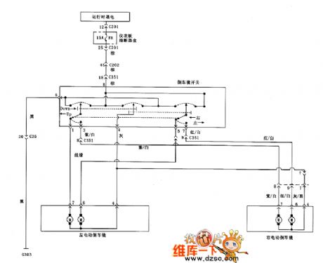
Shanghai Excelle front and rear fog lights circuit diagram
Published:2013/12/16 20:37:00 Author:lynne | Keyword: Shanghai Excelle front and rear fog lights circuit diagram,
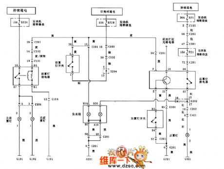
Shanghai Excelle front and rear fog lights circuit diagram shown in Figure:
(View)
View full Circuit Diagram | Comments | Reading(745)
Mercedes-Benz 190E external light circuit diagram
Published:2013/12/8 21:13:00 Author:lynne | Keyword: Mercedes-Benz 190E external light circuit diagram,
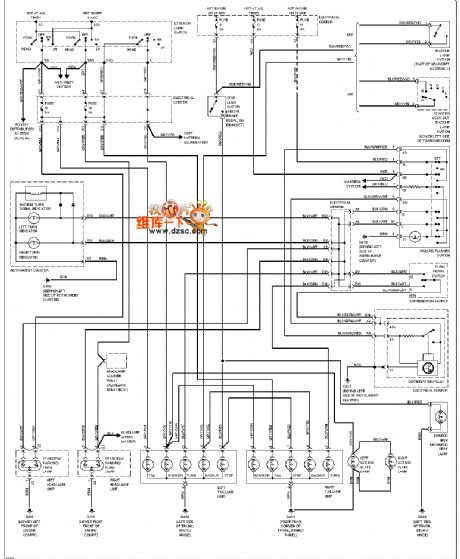
Mercedes-Benz 190E external light circuit diagram is shown below:
(View)
View full Circuit Diagram | Comments | Reading(2039)
Mercedes-Benz 190E GND Ground Distribution Diagram
Published:2013/12/8 21:16:00 Author:lynne | Keyword: Mercedes-Benz 190E GND Ground Distribution Diagram,
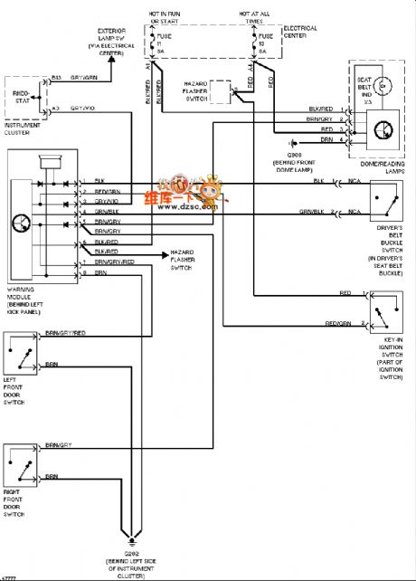
Mercedes-Benz 190E GND Ground distribution diagram is shown below:
(View)
View full Circuit Diagram | Comments | Reading(1494)
Mercedes-Benz 190E headlight circuit (no DRL)
Published:2013/12/8 21:18:00 Author:lynne | Keyword: Mercedes-Benz 190E headlight circuit (no DRL),
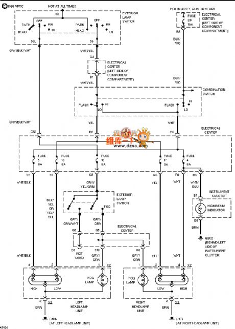
Mercedes-Benz 190E headlight circuit (no DRL) as follows:
(View)
View full Circuit Diagram | Comments | Reading(1175)
Mercedes-Benz 190E seat heater circuit diagram
Published:2013/12/8 21:19:00 Author:lynne | Keyword: Mercedes-Benz 190E seat heater circuit diagram,
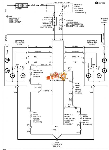
Mercedes-Benz 190E seat heater circuit diagram is shown below:
(View)
View full Circuit Diagram | Comments | Reading(1520)
4011 IC Circuit
Published:2013/12/2 21:05:00 Author:lynne | Keyword: 4011 IC Circuit
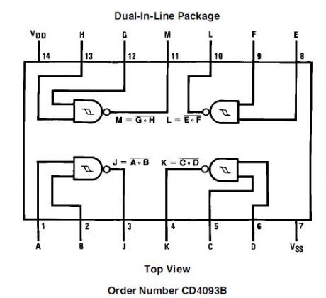
The HEF4011B is a quad 2-input NAND gate. The outputs are fully buffered for the highest noise immunity and pattern insensitivity to output impedance. It operates over a recommended VDD power supply range of 3 V to 15 V referenced to VSS (usually ground). Unused inputs must be connected to VDD, VSS, or another input.The device is suitable for use over both the industrial (-40 oC to +85 oC) and automotive (-40 oC to +125 oC) temperature ranges. (View)
View full Circuit Diagram | Comments | Reading(1770)
Electronic Lie Detector Circuits
Published:2013/11/26 20:11:00 Author:lynne | Keyword: Electronic Lie Detector Circuit
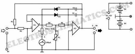
This electronic lie detector circuit project will give two readings: one for difficult questions for the subject and another to show its emotional state in general.The emotional states are detected not only by heart beat accelaration and trembling hands but also an increase in skin humidity whose resistance decreases causing the entry into operation of the lie detector.
Two electrodes can be used as a flexible wire, bare, wrapped around fingers or wrist.In order to not influence the measurement result the device must be powered from two 9 Volts batteries.
Each change in resistance, and therefore the voltage at the input circuit will be amplified by operational amplifier A1, which also serves as separator. The output signal will determine, by R3, a deviation of the measuring instrument.
General emotional state of a person can be assessed by measuring the average resistance of the skin over a period of time. The indication is provided by an indicator instrument connected to point B of the circuit. Operational amplifier A2 is connected as an integrator and allows the circuit to automatically adjust according to the average resistance of the skin.
Length of time to measure the skin resistance is determined by R5, C2 and C3. Until such time elapses, the lie detector gives no indication although diodes D1 and D3 provide a rapid response of the circuit.
Human skin lie detector schematic
Potentiometer P1 allows you to adjust the time delay of the circuit. Since skin resistance varies from one person to another, may be necessary to change the resistance value R1. This resistance can be replaced with a potentiometer.
Reading a great value to the instrument connected to the output of B indicates that subject’s skin resistance is low (which is a characteristic of people with sticky hands) and it is advisable to reduce the value of R1.
lie detector components listR1 = 47KR2 = 1MR3 = 3.3KR4 = 10KR5 = 10MP1 = 10KC1 = 100nC2 = C3 = 470nD1 = D2 = 1N4148IC1 = IC2 = LF356 (View)
View full Circuit Diagram | Comments | Reading(892)
Turn Off Battery Charging from Solar Panel at Nightfall
Published:2013/11/26 20:02:00 Author:lynne | Keyword: Turn Off Battery Charging from Solar Panel at Nightfall
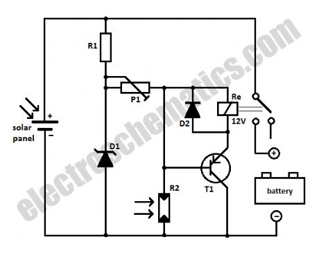
When loading a battery during the day from a solar panel it can be partially discharging through the panel after nightfall. This solar panel power switch circuit replaces the diode and connects the panel to battery through a relay contact.When the power supply voltage is too low the relay is not ON, so the battery is not connected to the solar panel.
When the voltage is high enough to engage the relay and the LDR receives enough light in order to open T1, the relay will switch and the battery will charge.
The relay remains ON even when the solar panel voltage starts to decrease. A battery connected and charged can not action the relay when the light intensity decreases because R2 will block T1. The brightness at which this occurs is set by P1.
Because the power consumption is determined primarily by the relay, it is important that the relay should be a miniature one, with high coil resistance but also be capable to switch up to 10 Amps.
Solar panel power switch schematic
Components list for solar panel to battery switchR1 = 100ΩR2 = LDR05P1 = 25KD1 = zener diode 9.1V / 1WD2 = 1N4148T1 = BC557 (View)
View full Circuit Diagram | Comments | Reading(1305)
Homemade Metal Detector Circuit
Published:2013/11/24 20:49:00 Author:lynne | Keyword: Homemade Metal Detector Circuit
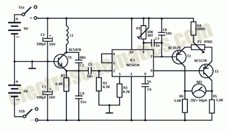

This homemade metal detector circuit will help you find objects composed of materials with relatively high magnetic permeability. It is not suitable for buried coins discovery that is not sensitive enough but you can detect pirates treasures!
google_ad_client= ca-pub-9265205501290597 ;google_ad_slot= 6648404198 ;google_ad_width=336;google_ad_height=280;
The metal detector is powered by 2 x 9V batteries, each of it charges with 15 mA. L1 detector coil is part of the sinusoidal oscillator built around transistor T1. Normally, the center frequency of the voltage controlled oscillator (VCO) from the PLL loop that is contained in IC1 is equal to the oscillation frequency of T1. This changes when entering a metallic object (ferrous or nonferrous) in the field induced by L1. S1 is a miniature 2-pole switch.
Meter needle deviation is a measure of frequency change, since the direction of deviation depends on the type of material detected by the coil.The meter tool used for this homemade metal detector is zero as central, +-50µA.
Coil L1 consists of 40 turns of enamelled copper wire, wound on a plastic template with a diameter of about 10 cm. Inductance thus obtained ensure the functioning of the oscillator at a frequency approximately equal to the VCO included in the PLL loop.
Metal detector circuit schematic
Use an oscilloscope to check that pin 2 of IC1 delivers sinusoidal signal with frequency about 75 kHz. Adjust P1 so that fronts rectangular signal from pin 4 to coincide with the peaks of the sinusoidal signal from pin 2. Then, adjust P2 in order to obtain 0 on the meter. Since the neutral zero setting “runs” with the battery’s decreasing voltage it will be necessary to restore it (zero balancing) from time to time during use of the homemade metal detector.
(View)
View full Circuit Diagram | Comments | Reading(1511)
David Moran’s Capacitor Meter Project
Published:2013/11/21 20:49:00 Author:lynne | Keyword: David Moran’s Capacitor Meter Project
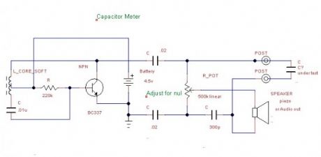
Hi guys, I just received an email from David Moran and he sent me his capacitor meter project with pictures and a little presentation. Here are the details and schematic.
Here is the schematic of my capacitor meter I built and have used quite a bit. It will measure from zero to 0.1uf with 300pf at mid range. It is an oscillator that makes noise fed into a bridge circuit that will null out the noise when balanced. Once built, you must clip in known value capacitors and hand calibrate the dial.I built my unit into a cheap push on battery light the output can go to a small audio amp, audio input of a computer, or try a piezo speaker. The noise is rather annoying, so you may want to use a scope to view it if you must test many capacitors.
Capacitor meter schematic
(View)
View full Circuit Diagram | Comments | Reading(1140)
| Pages:12/471 1234567891011121314151617181920Under 20 |
Circuit Categories
power supply circuit
Amplifier Circuit
Basic Circuit
LED and Light Circuit
Sensor Circuit
Signal Processing
Electrical Equipment Circuit
Control Circuit
Remote Control Circuit
A/D-D/A Converter Circuit
Audio Circuit
Measuring and Test Circuit
Communication Circuit
Computer-Related Circuit
555 Circuit
Automotive Circuit
Repairing Circuit