
Basic Circuit
Index 17
Lightning Strike Detection
Published:2013/8/13 4:05:00 Author:lynne | Keyword: Lightning Strike Detection
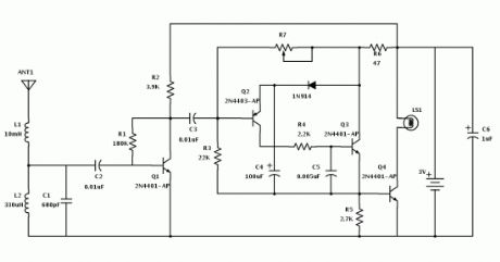
It picks up and amplifies signals in the 300 kHz range, where lightning makes a lot of noise that can be picked up with a radio. The antenna and receiver are tuned to 300 kHz, with the receiver’s output connected to an amplifier that drives the lamp flashing circuitry, alerting you to lightning in the area.Use the potentiometer to reduce the sensitivity to noise and still be able to detect lightning strikes. In addition to lightning, this will also respond to noise from motors inside appliances like refrigerators, washers, and air-conditioners. Another easy way to affect the sensitivity is to take off the antenna, or lengthen it depending on the conditions. To get some confirmation while tuning the detector, you can tune an AM radio to the bottom the of the dial as well.
You can use it to track weather, and be prepared for it. It is small enough and can be placed in a project box or waterproof container to use, on a boat for instance. The lamp can be replaced or even used alongside a buzzer to give an audible alert as well, so that constant monitoring is not necessary.
(View)
View full Circuit Diagram | Comments | Reading(1478)
AM Receiver Circuit
Published:2013/8/12 4:57:00 Author:lynne | Keyword: AM Receiver Circuit
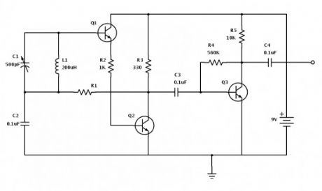
It can use general purpose transistors, and in this example there are 3 BC109C transistors. The schematic and BOM show a 200µH inductor and a trimmer capacitor 150-500pF, though these parts can be salvaged from an old AM radio, to preserve the directional nature of a tuning coil, and an adjustment knob (plate capacitor) that work well for radio reception.
The 120k resistor is for regenerative feedback between the Q2 NPN transistor and the input to the tank circuit. The value of this resistor is important to the performance of the entire AM receiver. In fact, it may be better to replace the fixed value with a variable resistor paired with a fixed resistor to adjust the oscillation and sensitivity. All the connections should be short to minimize interference.
Performance will vary depending on stray capacitance in your layout, the inductor winding/core/length, etc. Changing values of some of the capacitors, or adding them, as well as a potentiometer in the feedback loop can help with the performance of the receiver. With such a small circuit that is affected so much by its construction and its environment, a lot of hand tuning and experimentation will be fun, instructive, and possibly necessary to make it work best.
(View)
View full Circuit Diagram | Comments | Reading(1977)
POLICE SIREN
Published:2013/8/5 20:44:00 Author:lynne | Keyword: POLICE SIREN
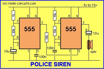
The Police Siren circuit uses two 555's to produce an up-down wailing sound. The first 555 is wired as a low-frequency oscillator to control the VOLTAGE CONTROL pin 5 of the second 555. The voltage shift on pin 5 causes the frequency of the second oscillator to rise and fall.
(View)
View full Circuit Diagram | Comments | Reading(2425)
ROULETTE
Published:2013/8/5 5:39:00 Author:lynne | Keyword: ROULETTE
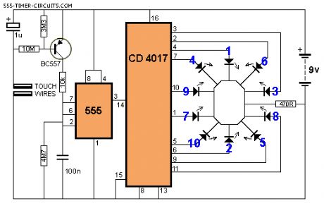
This circuit creates a rotating LED that starts very fast when a finger touches the TOUCH WIRES. When the finger is removed, the rotation slows down and finally stops. (View)
View full Circuit Diagram | Comments | Reading(1241)
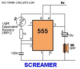
SCREAMER
Published:2013/8/5 5:38:00 Author:lynne | Keyword: SCREAMER

This circuit will produce an ear-piercing scream, depending on the amount of light being detected by the Light Dependent Resistor.
(View)
View full Circuit Diagram | Comments | Reading(1074)
SCREAMER circuit
Published:2013/8/5 5:37:00 Author:lynne | Keyword: SCREAMER circuit
This circuit will produce an ear-piercing scream, depending on the amount of light being detected by the Light Dependent Resistor.
(View)
View full Circuit Diagram | Comments | Reading(1050)
SERVO TESTER
Published:2013/8/5 5:35:00 Author:lynne | Keyword: SERVO TESTER
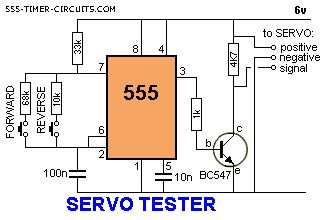
This circuit can be used to manually turn a servo clockwise and anti-clockwise. By pushing the forward or reverse button for a short period of time you can control the rotation of the servo. It will also test a servo. Here is a photo of a kit from Cana Kit for $10.00 plus postage (it is a slightly different circuit) and a motor and gearbox, commonly called a servo. The output shaft has a disk or wheel containing holes. A linkage or push-rod is fitted to a hole and when the disk rotates, the shaft is pushed and pulled. The shaft only rotates about 180� to actuate flaps or ailerons etc.
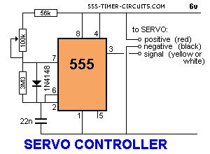
A pot can be used to control the position of the servo by using the following circuit. It produces a positive pulse between about 0.9 milliseconds and 2.1 milliseconds. The off period between pulses is about 40 milliseconds. This can be shortened by reducing the value of the 3M3 resistor. (View)
View full Circuit Diagram | Comments | Reading(1388)
SIREN 100dB
Published:2013/8/1 22:42:00 Author:lynne | Keyword: SIREN 100dB
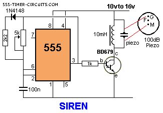
This is a very loud siren and if two or more piezo's are located in a room, the burglar does not know where the sound is coming from. A robber will not stay anywhere with an ear-piercing sound as he cannot hear if someone is approaching. It's the best deterrent you can get. The F contact on the piezo is feedback and is not needed in this circuit.
(View)
View full Circuit Diagram | Comments | Reading(1446)
TOY ORGAN
Published:2013/8/1 4:50:00 Author:lynne | Keyword: TOY ORGAN
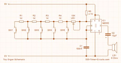
This circuit produces a tone according to the button being pressed. Only 1 button can be pressed at a time, that's why it is called a monophonic organ. You can change the 1k resistors to produce a more-accurate scale. (View)
View full Circuit Diagram | Comments | Reading(1519)
Reverse Bias Oscillators
Published:2013/7/30 20:41:00 Author:muriel | Keyword: Reverse Bias Oscillators
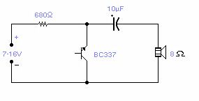
There are a number of npn transistors that will oscillate in the audio range when reverse biased. Minimum supply voltage is 7V for low power transistors such as BC109, BC238 and 2N2222A, it becomes 12V for medium power transistors such as BD139 and is 16V for power transistors as BUX22 and 2N6543. Current drain is 4mA at 9V and frequency of oscillation is 550Hz. The base is normally left open. (View)
View full Circuit Diagram | Comments | Reading(970)
Low-distortion Audio-range Oscillators
Published:2013/7/30 20:39:00 Author:muriel | Keyword: Low-distortion, Audio-range Oscillators
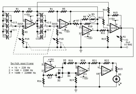
Parts:P1 10K Log. Potentiometer (Dual-ganged)P2 2K2 Linear PotentiometerR1,R2,R4,R5 3K3 1/4W ResistorsR3,R6 820R 1/4W ResistorsR7 10K 1/2W Trimmer CermetR8 22K 1/4W ResistorR9 Photo resistor (any type)R10 8K2 1/4W ResistorR11,R12,R14,R15 3K3 1/4W ResistorsR13 2K7 1/4W ResistorR16--R20 3K3 1/4W ResistorsR21 56K 1/4W ResistorR22 68K 1/4W ResistorR23 1K 1/4W ResistorC1,C6 220pF 63V Polystyrene CapacitorsC2,C7 8n2 63V Polyester CapacitorsC3,C8 82nF 63V Polyester CapacitorsC4,C9 150nF 63V Polyester CapacitorsC5,C10 680nF 63V Polyester CapacitorsD1--D4 1N4148 75V 150mA DiodesD5 LED 5mm. RedIC1,IC2 NE5532 Low noise Dual Op-ampsIC3 TL084 Quad BIFET Op-AmpSW1 2 poles 3 ways rotary switch
Comments:Producing low-distortion sine waves, this oscillator operates over the range 16 to 22000 Hz. The circuit is based on two articles that have appeared earlier in Wireless World - Roger Rosens' Phase -Shifting Oscillator , February 1982 pp. 38-41, and J. L. Linsley Hood's Wien-Bridge Oscillator with low harmonic distortion from May 1981 pp. 51-53.This design features the simplicity of the Rosens' circuit but avoids the use of a thermistor. Instead, oscillator stability is controlled by means of a common photo-resistor driven by a LED, as suggested in the Linsley Hood article.There is no settling time when the oscillator's frequency is changed and no bouncing of the output waveform. Use of an expensive and sometimes difficult to obtain thermistor is avoided.
Technical data:Output voltage:Sine wave, 1V RMS max. Total harmonic distortion @ 1V RMS output:Frequency Reading100Hz = 0.0035%300Hz = 0.0028%1kHz = 0.002 %3kHz = 0.002 %10kHz = 0.001 %
Notes:Any common photo-resistor and 5mm. red LED can be used, provided they are in close contact and enclosed in a light-proof small box. I used the metal screen of a small IF transformer for AM transistor radios sealed with black insulating tape.The 10K trimmer must be set to obtain a 1V RMS output.The circuit must be supplied by a + and - 15V dual regulated supply. Common 7815 and 7915 regulator ICs should be used for this purpose.
This circuit was awarded with publication in ELECTRONICS WORLD Circuit Ideas , February 2003 issue, page 38.
(View)
View full Circuit Diagram | Comments | Reading(1247)
Dome Lamp Dimmer
Published:2013/7/30 20:38:00 Author:muriel | Keyword: Dome Lamp Dimmer
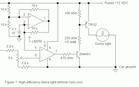
There are times when a little light inside the car would greatly assist one of the passengers but the dome light is too bright for safe driving. The dimmer circuit in fig. 1 may be added to an existing dome light or included with a new passenger spot lamp. The upper op-amp generates a 700 Hz sawtooth waveform which is compared to a setpoint voltage by the lower op-amp. When the sawtooth voltage is above the setpoint, the transistors turn on supplying current to the bulb. The setting of the potentiometer determines the width of the pulses sent to the lamp and therefore the average voltage. The lamp is dim when the potentiometer is set near the higher voltage. Since the TIP32 switches on and off instead of simply dropping the voltage like a power rheostat, the power it dissipates remains low and a heat sink is not necessary.
Many autos run power to lamps with only one wire using the car body for the return current path so the dimmer must interrupt the positive lead as shown. Simply cut the wire leading to the lamp and connect the lamp end to the collector of the TIP32 and connect the battery end to the circuit power input. Run an additional ground wire to the auto chassis from the circuit. This ground wire will not carry much current and may be a smaller gauge. (View)
View full Circuit Diagram | Comments | Reading(1106)
NE555 Basic Monostable
Published:2013/7/30 20:37:00 Author:muriel | Keyword: NE555, Basic Monostable
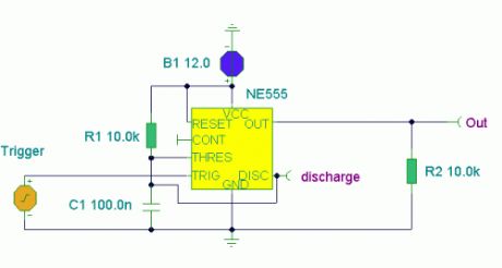
Notes:Here the popular 555 timing IC, is wired as a monostable. The timing period is precise and equivalent to:-
1.1 x R1 x C1
With component values shown this works out at approximately 1.1msec.The output duration is independant of the input trigger pulse, and the output from the 555 is buffered and can directly interface to CMOS or TTL IC's, providing that the supply voltages match that of the logic family.
The timing diagram above shows the output pulse duration, the trigger input and the output at the discharge terminal of the IC. (View)
View full Circuit Diagram | Comments | Reading(985)
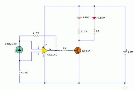
Infrared gates
Published:2013/7/29 20:20:00 Author:muriel | Keyword: Infrared gates
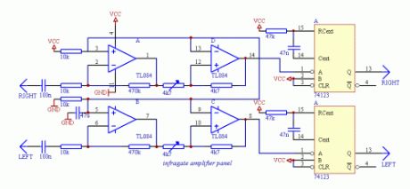
This is an infrared gate with two sensors planned to use in the wall in the way behind a door. It can be applied in a toilet to keep track of that someone is inside exceeding a certain amount of time. After that time elapsed, the circuit triggers the digital output wich can turn on a ventillator. The time period the output is turned on can be separately controlled by a second timer.If you plan to build this circuit, beware that you may have lots of difficulties though the schematic may seem simple. The construction of the circit requires some amount of equipment like an oscilloscope and a DVM, too. Without them, the device will do weird things you wouldn't expect, and even if it is correctly put together, you must adjust it with care both mechanically in its final place and electronically with the help of an oscilloscope. Only if you want to span about less than 20-30 inches with the infra diodes can forget about this calibration. Alternatively you can take ideas from this construction.
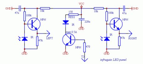
SchematicsThe device consists of several parts, the most critical one is the panel with the infra LEDs. I tried to use several receiver transistors, but best result was given by infra receiver diodes used in TV remote control receivers. The receiver diodes must be properly shielded from the transmitter LED(s) otherwise the infra light will surely drive the receiver with a large enough signal. These photodiodes should only see infrared light coming from the mirror. The two very sensitive receiver parts should also be isolated from the transmitter electrically or the TX signal will get across the wires to the RX lines, which results the same effect as weak optical shielding. Use metal shielding around the receiver amplifiers where possible. The infrared transmitter LEDs should be close in wavelength to the max. sensitivity band of the receivers. You can experiment with using more LEDs and more current testing several resistor values, but don't exceed the 500 mA current limit flowing on the diodes or they will burn out. Do not shield the transmitters, allow the maximum amount of infralight to reach the mirror to extend the possible range.
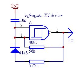
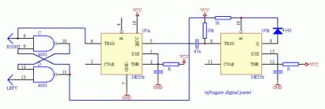
To start testing the infra LED panel, you wil need the infragate amplifier panel and the small transmiter driver. The TX driver will generate the digital signal for the LED driver on the LED panel. The digital signal is 1:10 on/off to achive good performance with lower power dissipation on the LEDs. Connect GND, VCC planes and LEFT, RIGHT wires of the LED panel with the amplifier panel, and drive the TX line from the TX driver. Now you are able to start testing and calibrating the analogue part of the circuit. If everything is ok, holding a mirror in front of the LED panel will reflect enough signal to overdrive the amplifier and you can check the output on the OPA 1, 7 pins with an oscilloscope. Taking the mirror farther on will result a weakening signal on the amplifier output. Set the orientation of the diodes to be able to get the maximum signal amplitude on the oscilloscope screen. This is the heaviest part of the work, don't deal too much with it until the complete circuit is not built. Just adjust a static state of the construction to give the maximum signal amplitude on the output when nothing is between the diodes and the mirror and give a small noise only when the line of sight is covered. If you are ready with it, you can adjust the schmitt triggers built of the other two OPA parts to generate TTL pulses when the analog signal is at its maximum and stay on the same DC level when the received signal is missing.
It is also important to protect the receiver diodes from direct light as natural light will weaken the sensitivity of the diodes, and lamps will transform the 50/60 Hz modulation present in the line power. Small noise is not problem, but the received signal from the TX generator should be stronger to be able to detect it. After the ST adjustments, connect LEDs to the 74123's TTL outputs through proper value resistors. The 74123 here is used as a demodulator. If there is a periodic signal change on the input, the output will be high, while if there is no activity on the input for a given period of time, the output falls low. When you cover the line of sight of one receiver diode, the corresponding LED turns off. There should not be any flickering in the turning on/off, the output should immediately respond to the change without blinking.
It is also important to protect the receiver diodes from direct light as natural light will weaken the sensitivity of the diodes, and lamps will transform the 50/60 Hz modulation present in the line power. Small noise is not problem, but the received signal from the TX generator should be stronger to be able to detect it. After the ST adjustments, connect LEDs to the 74123's TTL outputs through proper value resistors. The 74123 here is used as a demodulator. If there is a periodic signal change on the input, the output will be high, while if there is no activity on the input for a given period of time, the output falls low. When you cover the line of sight of one receiver diode, the corresponding LED turns off. There should not be any flickering in the turning on/off, the output should immediately respond to the change without blinking. (View)
View full Circuit Diagram | Comments | Reading(1032)
UNEVEN CLICKS
Published:2013/7/29 1:54:00 Author:lynne | Keyword: UNEVEN CLICKS
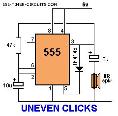
This circuit produces two clicks then a short space before two more clicks etc. Changing the voltage on pin, 5 via the diode, adjusts the timing of the chip.
(View)
View full Circuit Diagram | Comments | Reading(861)
Voltage Doubler
Published:2013/7/29 1:22:00 Author:lynne | Keyword: Voltage Doubler
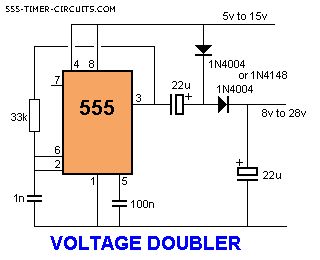
A voltage higher than the supply can be created by a Charge-Pump circuit created with a 555, diodes and capacitors as shown in the following circuit. The output will deliver about 50mA (View)
View full Circuit Diagram | Comments | Reading(0)
Heating System Thermostats
Published:2013/7/28 20:19:00 Author:muriel | Keyword: Heating System Thermostats
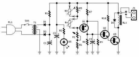
Parts:P1 1K Linear PotentiometerR1 10R 1/4W ResistorR2 1K 1/4W ResistorR3 3K3 @ 20°C n.t.c. Thermistor (see Notes)R4 2K2 @ 20°C n.t.c. Thermistor (see Notes)R5 10K 1/2W Trimmer CermetR6 3K3 1/4W ResistorR7,R9 4K7 1/4W ResistorsR8 470K 1/4W ResistorR10 10K 1/4W ResistorC1,C2 470µF 25V Electrolytic CapacitorsC3 1µF 63V Electrolytic CapacitorD1,D2,D4 1N4002 100V 1A DiodesD3 LED Red 3 or 5mm.Q1 BC557 45V 100mA PNP TransistorQ2 BC547 45V 100mA NPN TransistorQ3 BC337 45V 800mA NPN TransistorRL1 Relay with SPDT 2A @ 220V switchCoil Voltage 12V. Coil resistance 200-300 OhmJ1 Two ways output socketSW1 SPST Mains SwitchT1 220V Primary, 12 + 12V Secondary 3VA Mains transformerPL1 Male Mains plug & cable
Device purpose:This circuit is intended to control a heating system or central heating plan, keeping constant indoor temperature in spite of wide range changes in the outdoor one. Two sensors are needed: one placed outdoors, in order to sense the external temperature; the other placed on the water-pipe returning from heating system circuit, short before its input to the boiler. The output from the Relay contact must be connected to the boiler's start-stop control input.This circuit, though simple, has proven very reliable: in fact it was installed over 20 years ago at my parents' home. I know, it's a bit old: but it's still doing its job very well and without problems of any kind.
Circuit operation:When Q1 Base to ground voltage is less than half voltage supply (set by R7 & R9), a voltage is generated across R8 and the driver transistors Q2 & Q3 switch-on the Relay. When Q1 Base to ground voltage is more than half voltage supply, caused when one of the n.t.c. Thermistors lowers its value due to an increase in temperature, no voltage appears across R8 and the Relay is off.C3 allows a clean switching of the Relay.P1 acts as main temperature control.
Notes:R3 is the outdoor sensor, R4 the indoor sensor.If you are unable to find a 3K3 Thermistor for R3 you can use a 4K7 value instead. The different value can be easily compensated by means of Trimmer R5.R5 allows to set the heating system for outdoor temperatures ranging from about +10°C downwards. The higher R5's resistance the hotter the heating system and vice versa.The existing boiler thermostat should be set to its maximum value and not bypassed: it is necessary for safety's sake.This circuit can be dispensed with its differential feature and converted into a simple precision thermostat omitting R3. (View)
View full Circuit Diagram | Comments | Reading(1151)
Infra Red Remote Control Extenders
Published:2013/7/28 20:16:00 Author:muriel | Keyword: Infra Red , Remote Control , Extenders
View full Circuit Diagram | Comments | Reading(911)
TRIAC Light Dimmers
Published:2013/7/28 20:06:00 Author:muriel | Keyword: TRIAC Light Dimmers
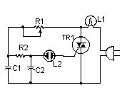
This little circuit can be used to dim lights up to about 350 watts. It uses a simple, standard TRIAC circuit that, in my expirience, generates very little heat. Please note that this circuit cannot be used with fluorescent lights.
PartsR1 50K PotR2 15K 1/2W ResistorC1, C2 0.068 250V CapacitorL1 Lamp To Be Controlled (up to 350 watts)L2 Neon LampTR1 40502 TRIACMISC Case, Knob, Heatsink For TR1, Wire, Socket For L1Notes1. This circuit is for 117VAC only. 220 or 240 V will burn up the circuit. L1 can be a maximum of 350 watts.2. The circuit must be installed and used in a case. (View)
View full Circuit Diagram | Comments | Reading(982)
Temperature-controlled Fan 1
Published:2013/7/28 20:05:00 Author:muriel | Keyword: Temperature-controlled Fan
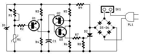
Parts:P1 22K Linear Potentiometer (See Notes)R1 15K @ 20°C n.t.c. Thermistor (See Notes)R2 100K 1/4W ResistorR3,R6 10K 1/4W ResistorsR4,R5 22K 1/4W ResistorsR7 100R 1/4W ResistorR8 470R 1/4W ResistorR9 33K 4W ResistorC1 10nF 63V Polyester CapacitorD1 BZX79C18 18V 500mW Zener DiodeD2 TIC106D 400V 5A SCRD3-D6 1N4007 1000V 1A DiodesQ1,Q2 BC327 45V 800mA PNP TransistorsQ2 BC337 45V 800mA NPN TransistorSK1 Female Mains socketPL1 Male Mains plug & cable
Device purpose:This circuit adopt a rather old design technique as its purpose is to vary the speed of a fan related to temperature with a minimum parts counting and avoiding the use of special-purpose ICs, often difficult to obtain.
Circuit operation:R3-R4 and P1-R1 are wired as a Wheatstone bridge in which R3-R4 generates a fixed two-thirds-supply reference voltage, P1-R1 generates a temperature-sensitive variable voltage, and Q1 is used as a bridge balance detector.P1 is adjusted so that the reference and variable voltages are equal at a temperature just below the required trigger value, and under this condition Q1 Base and Emitter are at equal voltages and Q1 is cut off. When the R1 temperature goes above this balance value the P1-R1 voltage falls below the reference value, so Q1 becomes forward biased, pulse-charging C1.This occurs because the whole circuit is supplied by a 100Hz half-wave voltage obtained from mains supply by means of D3-D6 diode bridge without a smoothing capacitor and fixed to 18V by R9 and Zener diode D1. Therefore the 18V supply of the circuit is not true DC but has a rather trapezoidal shape. C1 provides a variable phase-delay pulse-train related to temperature and synchronous with the mains supply zero voltage point of each half cycle, thus producing minimal switching RFI from the SCR. Q2 and Q3 form a trigger device, generating a short pulse suitable to drive the SCR.
Notes:The circuit is designed for 230Vac operation. If your ac mains is rated at about 115V, you can change R9 value to 15K 2W. No other changes are required.Circuit operation can be reversed, i.e. the fan increases its speed as temperature decreases, by simply transposing R1 and P1 positions. This mode of operation is useful in controlling a hot air flux, e.g. using heaters.Thermistor value is not critical: I tried also 10K and 22K with good results.In this circuit, if R1 and Q1 are not mounted in the same environment, the precise trigger points are subject to slight variation with changes in Q1 temperature, due to the temperature dependence of its Base-Emitter junction characteristics. This circuit is thus not suitable for use in precision applications, unless Q1 and R1 operate at equal temperatures.he temperature / speed-increase ratio can be varied changing C1 value. The lower the C1 value the steeper the temperature / speed-increase ratio curve and vice-versa. (View)
View full Circuit Diagram | Comments | Reading(1072)
| Pages:17/471 1234567891011121314151617181920Under 20 |
Circuit Categories
power supply circuit
Amplifier Circuit
Basic Circuit
LED and Light Circuit
Sensor Circuit
Signal Processing
Electrical Equipment Circuit
Control Circuit
Remote Control Circuit
A/D-D/A Converter Circuit
Audio Circuit
Measuring and Test Circuit
Communication Circuit
Computer-Related Circuit
555 Circuit
Automotive Circuit
Repairing Circuit