
Control Circuit
Index 220
The over-temperature and cooling alarm circuit
Published:2011/7/6 2:40:00 Author:qqtang | Keyword: over-temperature, cooling alarm
Working principle
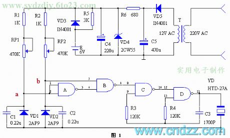
The circuit is shown in figure 1. The diodes of VD1 and VD2 are both located in the constant temperature box, when the temperature is below the lower limit, the LEV of figured point a is higher than the threshold voltage U of the gate A input terminal, the output terminal of gate A is in a low LEV, which makes gate B output a high LEV, at the moment, the oscillator composed of gate C and gate D is starting to vibrating, the piezoelectric chip is making the alarm sound; when the temperature is over the upper limit, the LEV at point b is lower than the voltage U of the gate B threshold, which can also makes gate B output a high LEV, and the piezoelectric chip is making the alarm sound. (View)
View full Circuit Diagram | Comments | Reading(752)
The over-temperature wireless alarm circuit
Published:2011/7/6 2:52:00 Author:qqtang | Keyword: over-temperature, wireless alarm
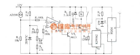
With modern electric technologies, it's common to install a set of constant temperature control device for some equipment that works in high temperatures. However, when the control equipment is malfunctioning in some special conditions, if there is a set of the over-temperature alarm device, the safety of the equipment can be secured. The over-temperature wireless alarm device is such a set of equipment which can emit the over-temperature alarm signal automatically when the temperature of the machine is too high.
(View)
View full Circuit Diagram | Comments | Reading(760)
The humidity detection and auto ventilation equipment circuit MS01-A
Published:2011/7/5 22:03:00 Author:Borg | Keyword: humidity detection, auto ventilation
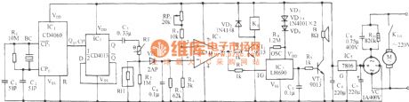
See as the figure, the circuit consists of the precise time-based oscillator, trigger D, temperature detection circuit, relay controlled ventilation circuit, auto reminding circuit and AC step-down rectifier circuit, etc. BC is made of the quartz of the watch, whose solid frequency is 32768Hz; K1 is JZC-22F; C6 and C7 are the electrolytic capacitor of CD11-16V; C3, C4 and C5 is the polyester film capacitor of CL11-63V type; R10 is the RJ-2W-820kΩ, RP1 is the WH5 integrated film potentiometer, the other resistors are all made of the RT-1/8W carbon capacitor; C8 is the CBB-400V-0.75μF; VC is adopted with the 1A/400V full bridge rectifier module. (View)
View full Circuit Diagram | Comments | Reading(706)
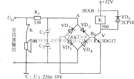
bridge and pick-up type speaker protection circuit
Published:2011/7/5 10:06:00 Author:John | Keyword: speaker
View full Circuit Diagram | Comments | Reading(3063)
Air pressure switch self-controlled circuit
Published:2011/7/5 10:05:00 Author:John | Keyword: Air pressure switch
The figure shows the air pressure switch self-controlled circuit, which uses the GYD-16 / C-type air pressure switch and contactor KM. The GYD shown in the figure is the air pressure switch. It directly controls the opening and closing action of AC contactor KM, thus being able to control the motor M to stop.
(View)
View full Circuit Diagram | Comments | Reading(717)
signal detection Y-△ starting circuit for preventing the coil from being disconnected
Published:2011/7/5 11:10:00 Author:John | Keyword: Y-△ starting circuit, coil
View full Circuit Diagram | Comments | Reading(901)
Zero sequence current phase protection circuit
Published:2011/7/6 4:46:00 Author:John | Keyword: Zero sequence current

The circuit is as shown, press the start button ST to lead the KM pulls. Then the motor M runs into normal operation. At this moment, three-phase load of the motor is balanced. Secondary current of the zero sequence current transformer TA is zero. The VT1 is off and the VT2 is inducted. The relay K (JR-4 type) pulls to lead the KM to be self-locked. When the phase is broken, current induced by TA’s secondary pole is rectified by the VD1, thus turning the VT1 from the deadline state to induction state. However, the VT2 is turned from the induction state to deadline state (VT2’s power supply is picked out from the winding around generator L on the KM coil, which is about 15 ~ 18V and used to power after being rectified by the VC).
(View)
View full Circuit Diagram | Comments | Reading(1159)
Zero sequence voltage off-phase protection circuit
Published:2011/7/6 5:01:00 Author:John | Keyword: off-phase protection
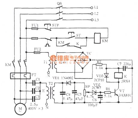
As shown in the figure, when the motor is within normal operation, the three-phase power supply is connected to three capacitors Y with the equal capacitance. Then potential of its contact E is 0V and the secondary side of transformer T2 is with no output voltage. As a result, when the VT is turned off, the K is released and its normally closing contacts are normally closed. And KM coils work properly. When any phase of the three-phase power supply is off, contact E values several volts due to the unbalanced three-phase. The voltage is gone through the transformer T2, VD1 rectifier, C4 and C5 filters, VD2 regulator, C6 and delay resistor R1. Afterwards, the voltage is added to the VT base to induct VT. K acts to cut the normally closing contacts of K. The KM circuit is cut off and the motor M stops working without electricity.
(View)
View full Circuit Diagram | Comments | Reading(1926)
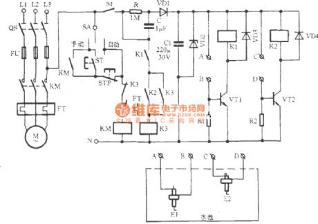
waste automotive spark plug for achieving water level control circuit
Published:2011/7/6 5:03:00 Author:John | Keyword: automotive spark plug, water level
View full Circuit Diagram | Comments | Reading(1932)
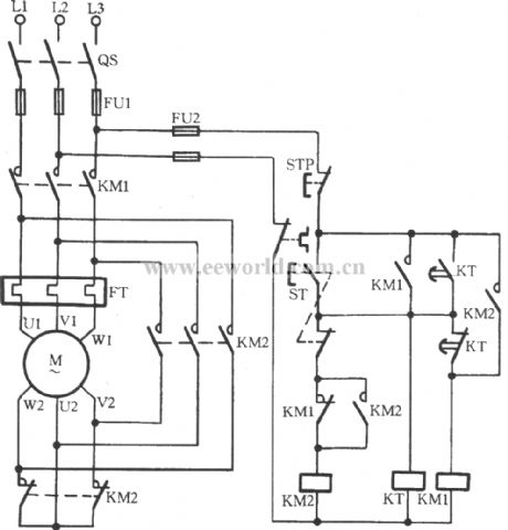
two contactors for composing Y-△ step-down start-up circuit
Published:2011/7/6 5:04:00 Author:John | Keyword: Y-△, contactor
View full Circuit Diagram | Comments | Reading(981)
The simple protection plug circuit of color TV
Published:2011/7/6 2:25:00 Author:qqtang | Keyword: protection plug, color TV
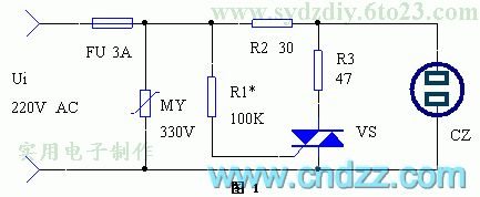
The circuit of the device is shown in Figure 1, which consists of VDR MY and the dual-way SCR VS. The main function of MY is to absorb the flooding wave in the grid and avoid large current impact of starting up, as it is in the first pass of the power supply of color TV, so it can purify the grid power supply, reduce the disturbance and clear the screen image; VS is the electric switch, which is conducting and generating the short current to blow the fuse when there is the fault phase in the grid, so the power supply of the color TV is cut off. (View)
View full Circuit Diagram | Comments | Reading(755)
The electric alarm flash lamp circuit of transistors
Published:2011/7/6 1:38:00 Author:qqtang | Keyword: electric alarm, flash lamp
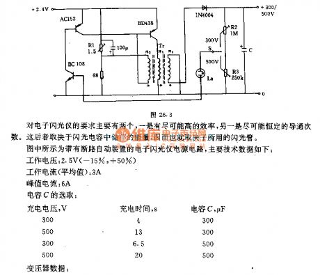
There are two requirements on the electric flash device, the first is a high efficiency, the other is the constant conducting times. The latter depends on the energy stored in the flash capacitor, so it also depends on the flash pipe in use. In the figure is the electric flash device light source circuit with the auto power-off equipment, whose main technical data are as follows:Working voltage: 2.5v(-15%,+15%)Working current(average value):3APeak current:6ACapacitor selection:Charge voltage,V charge time,s capacitor C, μF 300 4 300 500 13 300 300 6.5 500 500 20 500
Transformer data: (View)
View full Circuit Diagram | Comments | Reading(700)
The contactor wielding protection circuit of the air compressor
Published:2011/7/5 21:27:00 Author:Borg | Keyword: protection circuit, air compressor
View full Circuit Diagram | Comments | Reading(1645)
The auto reset over-voltage protection circuit
Published:2011/7/5 21:24:00 Author:Borg | Keyword: auto reset, over-voltage protection
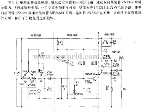
The circuit in figure 5.41 includes the power supply, trigger starting and control circuit, it controls ON/OFF of the load R1 with the help of the dual-way thyristor ZN6346. Once the AC power supply voltage is too high, the voltage on point A of the stable element LN5314 will be rising up, which makes the single-way thyristor 2N5060 conducting and transistor MPS6581 break down, so is the thyristor 2N6239, so the main dual-way thyristor is broken down, the load is protected from being broken due to over-voltage.
(View)
View full Circuit Diagram | Comments | Reading(1318)
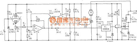
The auto ventilation and language warning circuit of combustible gas over-content
Published:2011/7/5 21:14:00 Author:Borg | Keyword: auto ventilation, language warning circuit, combustible gas over-content
View full Circuit Diagram | Comments | Reading(711)
The combustible gas full-automation lighter
Published:2011/7/5 21:11:00 Author:Borg | Keyword: combustible gas, full-automation

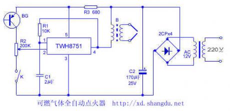
This device is fixed with a TWH8751 power integrated chip which consists of the high-voltage electric sparkle lighting equipment, and the equipment is under the control of the fire feedback light signal, so the device has the function of re-lighting after being put out. The device can fulfill the auto cook with other circuits. TWH8751, R1 and C1 compose the square wave generator. B2 is a booster, which can be replaced by the 12 inch high-voltage package, or the output transformer that the first stage is rolled for 30 turns by the 0.3mm wire or that is used in the valve radio.
(View)
View full Circuit Diagram | Comments | Reading(2238)
The language calling circuit of combustible gas leakage
Published:2011/7/5 20:56:00 Author:Borg | Keyword: language calling circuit, combustible gas leakage
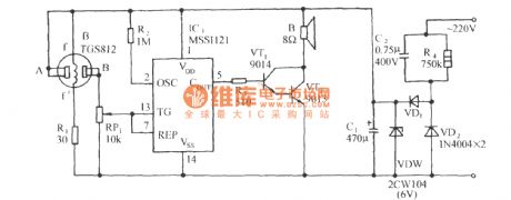
See as the circuit in the figure, it consists of the gas sensor, language generating circuit and AC step-down rectifier circuit, etc. (View)
View full Circuit Diagram | Comments | Reading(787)
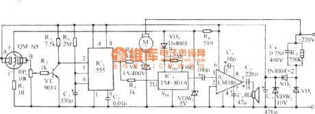
The auto ventilation and language circuit of harmful gas exceeding in the combustible gas bathroom
Published:2011/7/5 20:52:00 Author:Borg | Keyword: auto ventilation, language reminding circuit,
View full Circuit Diagram | Comments | Reading(576)
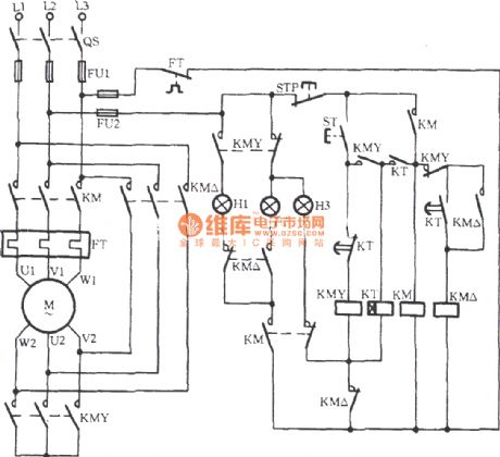
The self-coupled step-down starting circuit of avoid main contactor wielding accidents
Published:2011/7/5 20:47:00 Author:Borg | Keyword: self-coupled, step-down, wielding accidents
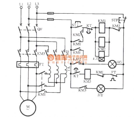
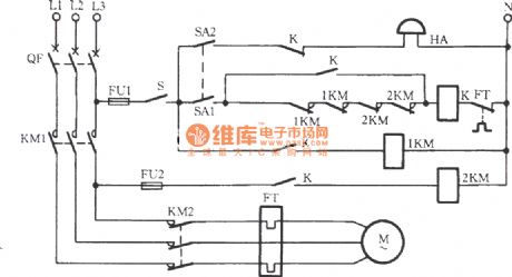
In the circuit, the additional mixed contactors of KM1 and KM2 and the time delay contactor of KT are serially connected as a OR logic circuit. When it is the starting time, KT is taking action, the KM1 and KM2 coil circuit are cut off, KM1 and KM2 additional contactors are reset. Meanwhile, if the main contactors of KM1 and KM2 are wielded, the contactors which are cut off by KM1 and KM2 can cut off the current that cross the transformer coil, so the accident of serious heat or break of TA duo to contactor wielding can be avoided. (View)
View full Circuit Diagram | Comments | Reading(2029)
The frequency speed circuit with a remote control box
Published:2011/7/5 20:36:00 Author:Borg | Keyword: frequency speed circuit, remote control box
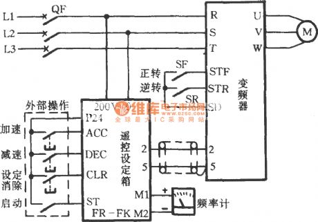
In the circuit , FR-FK is a remote control box. When the converter can't be operated due to the environment or the environment protection condition, or it can't be centrally controlled, this circuit can be used to solve these problems. The remote control box(module) connects with 3 external keys (acceleration, deceleration and offset) and a starting switch. When it is operated, the switch is closed first, and other keys are pressed according to need. The terminals of M1 and M2 of FR-FK are connected with the frequency counter, whose 2-pin and 5-pin are linked with the 2-pin and 5-pin of the converter shielding line. (View)
View full Circuit Diagram | Comments | Reading(654)
| Pages:220/312 At 20201202203204205206207208209210211212213214215216217218219220Under 20 |
Circuit Categories
power supply circuit
Amplifier Circuit
Basic Circuit
LED and Light Circuit
Sensor Circuit
Signal Processing
Electrical Equipment Circuit
Control Circuit
Remote Control Circuit
A/D-D/A Converter Circuit
Audio Circuit
Measuring and Test Circuit
Communication Circuit
Computer-Related Circuit
555 Circuit
Automotive Circuit
Repairing Circuit