
Control Circuit
Index 204
remote control tri-proportion controller circuit
Published:2011/7/12 7:37:00 Author:Lena | Keyword: remote control, tri-proportion controller
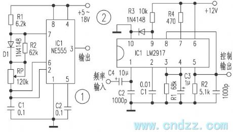
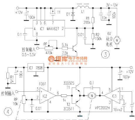
The tri-proportion controller is used to control electromotor rotate speed or oil plants engine accelerograph bulk etc in various power remote control models. Here introduces code/encode and control circuit which can realize above functions.This device realizes the remote tri-proportion control by altering transmitter modulation frequency. Figure 1 is the transmitter frequency regulation circuit, altering the bulk of potentiometer RP can make oscillator frequency change between 100Hz and 1 kHz, the output end of this circuit connects modulation input of high frequency transmitter.
(View)
View full Circuit Diagram | Comments | Reading(638)
radio frequency chip RF401 and constituted high credibility remote control circuit
Published:2011/7/12 3:40:00 Author:Lena | Keyword: radio frequency chip, high credibility, remote control
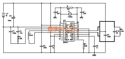
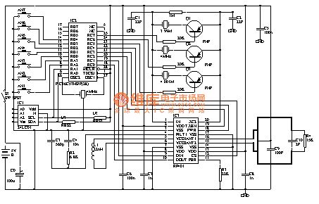
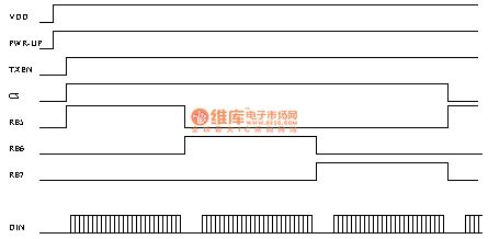
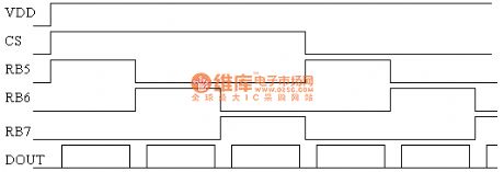

RF401 is Norway Nordic company newly protrusive data transmission band 433MHZ single piece wireless transceiver chip, this chip integrates high frequency transmitting, high frequency receiving, PLL synthesization, FSK modulation, FSK demodulation, multi-channel switch etc function, and has excellent performance, low power loss, easy usage etc features. Periphery components of nRF401 are very few, only involve one criterion crystal oscillator and few passive devices without debugging parts, this brings huge convenience for development and manufacture.Table 1 is NRF401 electric performance parameters.Table 2 is NRF401 pin function diagram.
Paremeters
Value
Unit
工作频道
433.92/434.33
MHz
调制方式
FSK
频偏
15
KHz
谢频输出功率 0.4k,3v
10
dBm
接收灵敏度 0.4k,BR=20 kbit/s BER<10
-105
dBm
最大传送数码率
20
K bit/s
适用电压范围
2.7~5.25
V
接收状态功耗
250
uA
发射状态功耗 -10 dBM
8
mA
等待状态功耗
8
8uA
Pin
Name
Pin function
Description
1
XC1
输入
参考振荡器输入端
2
VDD
电源
电源端口 (+3-5V DC)
3
VSS
地
地 (0V)
4
FILT1
输入
滤波器接入端口
5
VCO1
输入
压控振荡电感端口
6
VCO2
输入
压控振荡电感端口
7
VSS
地
地 (0V)
8
VDD
电源
电源端口 (+3-5V DC)
9
DIN
输入
发射数据输入
10
DOUT
输出
接收数据输出
11
RF_PWR
输入
射频功率设置
12
CS
输入
通道选择CS= 0 =>433.92MHz(Channel#1)CS= 1 =>434.33MHz(Channel#2)
13
VDD
电源
电源端口 (+3-5V DC)
14
VSS
地
地 (0V)
15
ANT2
输入/输出
天线接口
16
ANT1
输入/输出
天线接口
17
VSS
地
地 (0V)
18
PWR_UP
输入
电源 开/关PWR_UP= 1 =>Power up (Operating mode)PWR_UP= 0 =>Power down (Standby mode)
19
TXEN
输入
工作模式TXEN = 1 => Transmit modeTXEN = 0 => Receive mode
20
XC2
输出
参考振荡器输出端
 (View)
View full Circuit Diagram | Comments | Reading(1675)
practicality electromotion curtain remote control circuit
Published:2011/7/12 3:41:00 Author:Lena | Keyword: practicality, electromotion curtain, remote control

The transmitting/receiving part of this device uses T966/T988 multiway wireless transceiver module. The transmitting part adopts T966 2-key type emitter, and the receiving part work principle is shown in the figure.Turn on the power supply, IC3 is restored, Q(① pin) and Q(11 pin ) output low level, T1 and T2 cut-off, J1 and J2 are not absorbed, motor M stops, the curtain jibs. When press remote control transmitting key C, C end of IC1 outputs high level, VD1 cuts-off, I0 end outputs high level, then the high level shape is changed through IC2A, IC2B and is sent to CK(③ pin) end of IC3A.
编 号
名 称
型 号
数 量
R1、R2
电阻
10K
2
R3
电阻
1K
1
R4、R5
电阻
22K
2
C1、C2、C3、C5
涤纶电容
0.01u
1
C4
电解电容
220u/25V
1
C6
电解电容
100u/16V
1
C7
金属化纸介电容
1
LED1-LED3
发光二极管
3
VD1-VD6
开关二极管
IN4148
6
VD7、VD8
整流二极管
IN4001
2
T1、T2
晶体三极管
8050
2
IC1
无线接收模块
T988
1
IC2
六反相器
CD4049、CD4069
1
IC3
双D触发器
CD4013
1
J1、J2
电磁继电器
V=12V
2 (View)
View full Circuit Diagram | Comments | Reading(1236)
four coding remote control regulating light switch circuit
Published:2011/7/12 3:41:00 Author:Lena | Keyword: four coding, remote control, regulating light, switch

1. remote control transmitting circuit. This circuit is shown in figure 1. It consists of infrared coding remote control transmitting integrated circuit PT2248. The oscillating end has 500kΩ resistance internally, so it only needs external connecting ceramics filter or LC series resonance circuit, then it can generate surge to make the circuit work, in the figure 1, X1 is a 455kHx ceramics filter. ~pin and ~pin of PT2248 form keyboard matrix, this remote control switch only uses four keys which is marked with number 1, 2, 3, 4, to control the four receptors respectively.
(View)
View full Circuit Diagram | Comments | Reading(1161)
remote control discolored droplight(TDC1808/TDC1809)
Published:2011/7/12 7:44:00 Author:Lena | Keyword: remote control, discolored, droplight

This circuit uses DTMF encode mode to control quadruplet lamplight. In the emitter circuit, DTMF encoder's row line end and low line end external connect 4×4 standard keyboard, which can generate 16 instruction coding. When press the key, mute signal output end MUTE outputs low level, and make the LED connected externallyblink as transmitting indication. Encoded signal is outputted by TONE end of MK5087, and be sent to transmitting component TDC1808 by resistance R2 and then be transmitted outside. In the receiving circuit, receiving component TDC1809 receives demodulated outputted signal, which is sent to DTMF encoder YN9102 to be coded.
(View)
View full Circuit Diagram | Comments | Reading(597)
SBXl492-51/52 (TV, video tape recorder, audio equipment, air conditioner and toy) infrared remote control receiving circuit
Published:2011/7/12 7:17:00 Author:Christina | Keyword: TV, video tape recorder, audio equipment, air conditioner, toy, infrared, remote control, receiving circuit
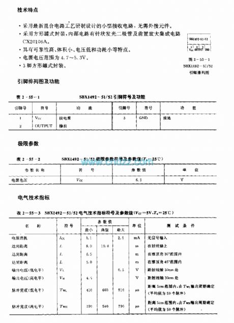
The SBXl492-51/52 is designed as one kind of infrared remote control receiving circuit that can be used in the TV, video tape recorder, audio equipment, air conditioner and toy applications. The carrier frequency of the SBXl492-51 is 40kHz, the carrier frequency of the SBXl492-52 is 38kHz.
Features
It is one kind of small receiving circuit which uses the latest hybrid circuit technology, it does not need the external components;It uses the square tank package, the internal circuit has the needle-like light-emitting diode and the preamplifier IC CX20106A;It has the features of high reliability, small volume and low power consumption;The voltage range of the power is 4.7-5.3V;It is in the 3-pin square tank package.
(View)
View full Circuit Diagram | Comments | Reading(368)
SBX1483—11/12/51/52 (TV, video tape recorder, audio equipment, air conditioner and toy) infrared remote control receiving circuit
Published:2011/7/12 7:24:00 Author:Christina | Keyword: TV, video tape recorder, audio equipment, air conditioner, toy, infrared, remote control, receiving circuit
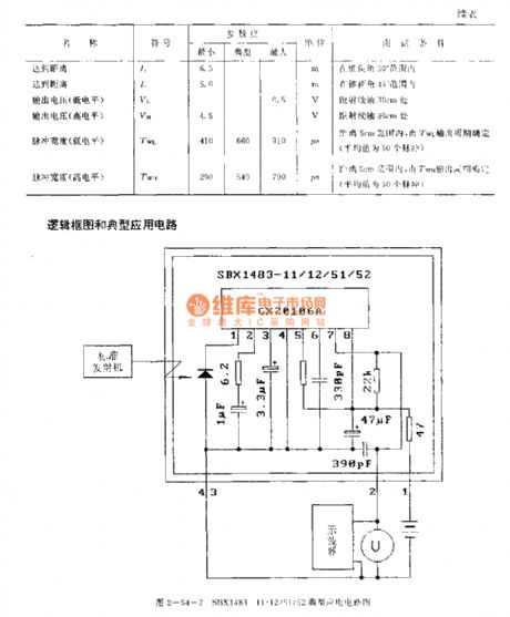
The RX-1387/BX-1407 is designed as one kind of infrared remote control receiving circuit that can be used in the TV, video tape recorder, audio equipment, air conditioner and toy applications. The carrier frequencies of the SBX1483-11 and SBX1483-51 are 40kHz, the carrier frequencies of the SBX1483-12 and SBX1483-52 are 38kHz. The SBX1483-11 and SBX1483-12 use the photoelectric receiving conductive film, and the SBX1483-51 and SBX1483-52 do not use the photoelectric receiving conductive film.
Features:
It is one kind of small receiving circuit which uses the latest hybrid circuit technology, it does not need the external components;It uses the square tank package, the internal circuit has the needle-like light-emitting diode and the preamplifier IC CX20106A;It has the features of high reliability, small volume and low power consumption;The voltage range of the power is 4.7-5.3V;It is in the 4-pin square tank package.
(View)
View full Circuit Diagram | Comments | Reading(1739)
Temperature Compensation Circuit
Published:2011/7/11 6:07:00 Author:Robert | Keyword: Temperature, Compensation
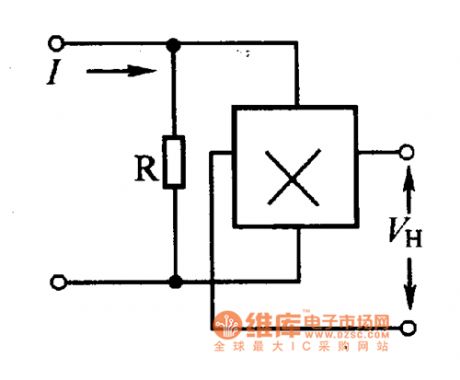
The error caused by the temperature could be compensated by the method of using parallel resistances. Its calculated formula is R=βRin/α.β. The Rin could be found in the parameter table. Its specific circuit is shown in the picture.
The picture shows the temperature compensation circuit. (View)
View full Circuit Diagram | Comments | Reading(481)
Changing Rate Control Circuit of Variable Converting Speed
Published:2011/6/14 13:00:00 Author:Michel | Keyword: Variable Converting Speed, Changing Rate Control
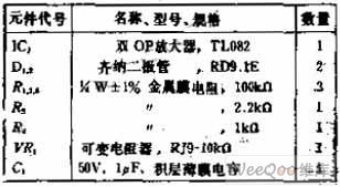
Circuit's FunctionsThis type of circuit uses a certain rate to limit rapid changing signal which can change electrical signals into part of mechanical signal output circuit.Converting speed depends on integral constants and if conversion speed is required to be variableand it usually comes out by changing integrating resistor.This circuit parts the integral input voltgae to alter time constants.
Circuit's Work PrincipleOP amplifier A1 is voltage comparator,A1 is saturated around +VO when the positive potential is input because reverse phase input grounds. (View)
View full Circuit Diagram | Comments | Reading(465)
Temperature Control Circuit of Transistor Temperature Sensor
Published:2011/7/7 15:54:00 Author:Michel | Keyword: Transistor, Temperature Sensor, Temperature Control Circuit
This picture is temperature control circuit of transistor temperature sensor.In this circuit,the voltage and tempreature between the base and emitter is inversely proportional.RP2, R3 ,r4-g9 and it consititute bridge road together.A1 amplifies the unbalanced voltage of the bridge road.A1 outputs 100 mV votlage u when the temperature changes 1 ℃.Please adjust RP2 and when the temperature is 0℃,A1 outputs 0V.Please adjust RP2 and when the temperature is 1℃,A1 outputs 100mV. (View)
View full Circuit Diagram | Comments | Reading(594)
Controlling a motor in three places
Published:2011/7/10 22:21:00 Author:Lucas | Keyword: Controlling motor , in three places
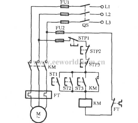
It is often referred as multi-point control in two or more than two locations to control of a motor (action). The circuit shown as the chart can realize controlling a motor in three locations. In the figure, ST is the start button, and STP is stop button. ST1, STP2 are the control buttons in the first place; ST2, STP2 are the control buttons in the second place; ST3, STP3 are the control buttons in the third place. The circuit connecting tips for realizing multi-point control: start buttons are connected in parallel, and stop buttons are connected in series.
(View)
View full Circuit Diagram | Comments | Reading(564)
Three-phase motor contactor interlock action for switching circuit
Published:2011/7/10 22:26:00 Author:Lucas | Keyword: Three-phase motor, contactor interlock
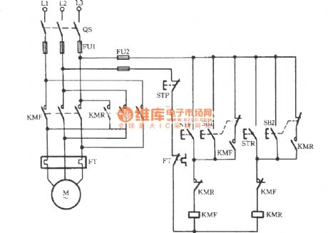
The circuit which uses contactor interlock for switching is shown. The STF and STR respectively refer to positive and reverse button. SB and SB2 are respectively positive and reverse jog buttons. And SB1 and SB2 are respectively equipped with a composite button. The dashed line in the figure indicates that the two contacts are the same button. For example, when the button SB1 is pressed, the motor would jog to run with the broken of the normally closed contacts.
(View)
View full Circuit Diagram | Comments | Reading(3717)
Motor protector circuit diagram 9
Published:2011/6/13 23:38:00 Author:Lucas | Keyword: Motor protector

The motor protection circuit is composed of the start control circuit, phase detection circuit and protection implementation circuit, the circuit is shown as the chart. Control circuit is composed of starter button S2 and stop button S1 and so on. Phase failure detection circuit consists of the current transformer coil TA, rectifier diode VD1, resistor R1, capacitor C and potentiometers RP1 and RP2 and so on. Protection implementation circuit is composed of the transistors V1 ~ V3, relay K, AC contactor KM and other components. Pressing the start button S2 (S2a and linkage 52b) will make the AC contactor KM and its normally open contacts (moving together contact) KM1 ~ KM4 pull in, the motor M operates to generate 1.2V induced voltage in ⒕, the voltage is rectified by VD1 to make V2 be saturated conduction. At this point, the 52b is off, V1 stops, V3 turns on, relay K pulls in and works, its normally open contact Κ is connected, hands being away the start button S2 will maintain the normal operation of motor M.
(View)
View full Circuit Diagram | Comments | Reading(2012)
The gas limiting alarm miner lamp circuit diagram 1
Published:2011/7/6 22:06:00 Author:Lucas | Keyword: Gas limiting, alarm , miners lamp
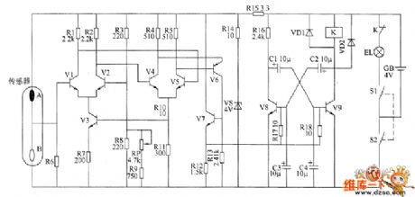
The gas limiting alarm miner's lamp circuit is composed of the detection amplifier circuit, and the circuit is shown as the chart. RP uses synthetic carbon potentiometer. C1 ~ C4 select aluminium electrolytic capacitor with the withstang voltage being more than 6.3V. VD1 and VD2 use 1N4007 or 2CP22 silicon rectifier diodes. VS selects 2CW11 silicon regulator diode. V1 ~ V5 and V7 select 59013 or 3DK4 silicon NPN transistors; V6 uses 59012 or 3CG21 silicon PNP transistor; V8 and V9 select 58050 silicon NPN transistors. K uses 4099 or JRC-5M DC relay. The sensor uses carrier catalytic gas sensor. Power switch S, miner's lamp EL, battery CB are the accessories of the original miner's lamp.
(View)
View full Circuit Diagram | Comments | Reading(597)
consisting of TWH8751 lock control anti-theft alarm circuit
Published:2011/7/8 3:20:00 Author:Fiona | Keyword: lock control anti-theft alarm
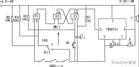
Figure shows the lock control anti-theft alarm circuit. The circuit consists of RS flip-flop, gated oscillator, the alarm circuit and so on.RS flip-flop consists of the NAND gate F2, F3, strobe oscillator consists of integrated circuits TWH8751 and R, C.
When the SKK is in the lock position, and the input 2 of NAND gate F1 is high, the state of DBK1-n is direct reflected by F1, if DBK1-n has an open circuit, the F1 output is low, RS flip-flop is set to 1 ,Choose the end (2) feet of the corresponding TWH8751 is low, trigger oscillator starts to oscillate, the oscillation signal makes the loudspeaker alarm.
(View)
View full Circuit Diagram | Comments | Reading(784)
Two electric motors one after one start-up circuit
Published:2011/7/10 20:18:00 Author:John | Keyword: electric motor, motor, one after one start-up
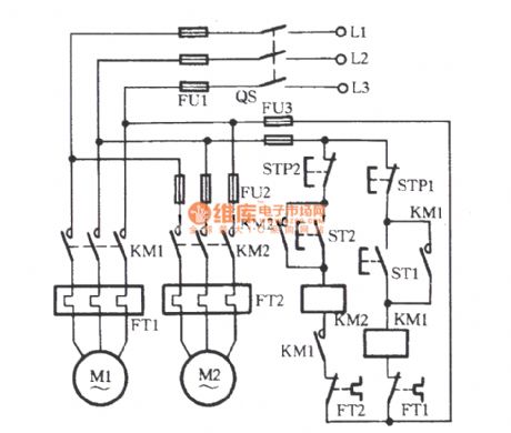
Procedures: Firstly, the starting button ST1 of the motor M1 is pressed to lead the KM1 coil to be energized. When the main contacts are closed, the motor M1 is launched to be self-locked. And the other pair of normally opening contact closes to induct the line circuit between KM2 and FT2. Then, press the starting button ST2 of the motor M2. The AC contactor KM2 would be powered to drive the electric motor M2 to start.
(View)
View full Circuit Diagram | Comments | Reading(1855)
LK001 selection frequency music outlet circuit
Published:2011/7/10 20:16:00 Author:John | Keyword: selection frequency music outlet

The circuit is as shown. It includes sound sensor BM, voice controlled IC, thyristor control circuit, imitation sound circuit and AC step-down rectifier circuit. Voice-specific integrated circuit LK001 is the core device of the circuit, whose internal function block circuit is shown.
(View)
View full Circuit Diagram | Comments | Reading(649)
Wire connection incandescent lamp life extension switch circuit
Published:2011/7/4 0:46:00 Author:John | Keyword: switch, incandescent lamp
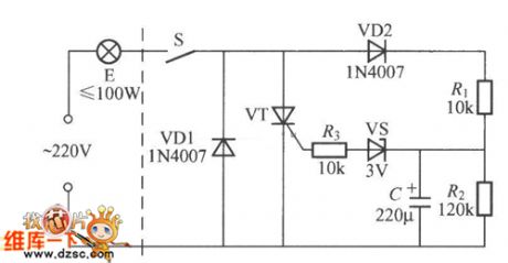
A wire connection incandescent lamp's life extension switch is shown. As its warm-up time is long, the service life of the bulb E is long. When the switch S is closed, 220V AC only has the negative half-cycle and powers bulb E through the VD1 and S. At this time, it is under the semi-pressure warm-up state. AC’s positive half-cycle charges the capacitor C through the VD2 and R1 and R2 divider until the voltage across C rises to more than 3V. Then the regulator thyristor VS is breakdown to conduct VT. Therefore, the bulb E is under total pressure to light.
(View)
View full Circuit Diagram | Comments | Reading(845)
UPS instantly switching Y-△ starting circuit
Published:2011/7/10 20:20:00 Author:John | Keyword: KM4, Y-△ starting
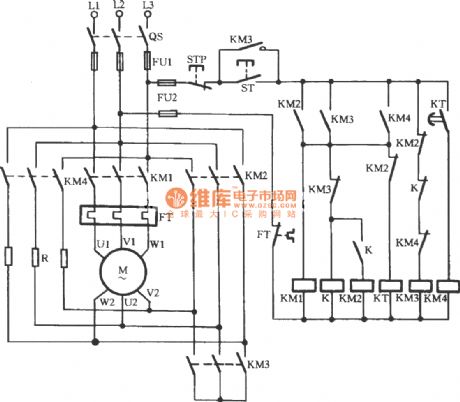
As for conventional Y-△ starting motors, when the motor shifts from a Y-shaped to △ running, phase short circuit often occur. In order to prevent phase short circuit, motor winding generator usually occur with power outages, thus inevitably for the formation of a strong secondary impact of current for the grid and the motor itself. The circuit is shown, which can achieve the uninterruptible power supply during the operation of shifting from Y-shaped to △ running. Besides, the voltage of the motor winding is not the line voltage which is directly from the Y-phase voltage to start operation of the △-shape. Actually, it has gone through a transition to an intermediate voltage level.
(View)
View full Circuit Diagram | Comments | Reading(1521)
zero sequence current protection with ultilizing third harmonic pressure velocity saturation circuit
Published:2011/7/10 20:19:00 Author:John | Keyword: current protection, third harmonic pressure velocity saturation

The shown circuit is suitable for △ or Y-shaped connection of the three-phase motor with rather great capacity. Off phase is to adopt a speed differential current transformer saturation TA, whose primary side is connected to the main circuit in series and secondary side’s head and tail is connected in series to form the open triangle. At the moment that the three-phase supply current (equal) is symmetrical, third harmonic voltage generated by TA is gone through the rectifier VC and the filtering capacitor C. So the sensitive K relay takes action to drive the motor M to run normally. When there is one phase is off, the remaining two-phase’s line current is with contrasting phase. And their synthetic current is zero for releasing the K and disconnecting the main circuit of the motor.
(View)
View full Circuit Diagram | Comments | Reading(1216)
| Pages:204/312 At 20201202203204205206207208209210211212213214215216217218219220Under 20 |
Circuit Categories
power supply circuit
Amplifier Circuit
Basic Circuit
LED and Light Circuit
Sensor Circuit
Signal Processing
Electrical Equipment Circuit
Control Circuit
Remote Control Circuit
A/D-D/A Converter Circuit
Audio Circuit
Measuring and Test Circuit
Communication Circuit
Computer-Related Circuit
555 Circuit
Automotive Circuit
Repairing Circuit