
Control Circuit
Index 208
Telephone burglar alarm circuit
Published:2011/7/9 9:53:00 Author:Fiona | Keyword: burglar alarm
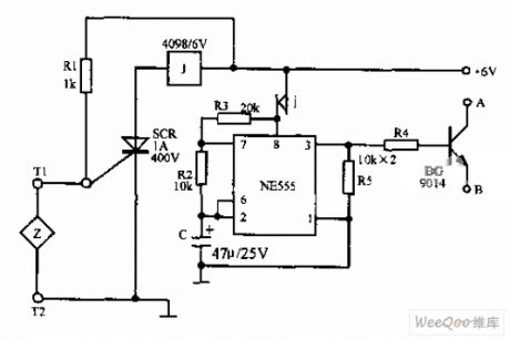
Telephone burglar alarm circuit is shown as above,it is formed by the SCR,relay,NE555 and peripheral components. When the sensor Z is connected, the whole machine is in waiting state,the circuit works. A, B are respectively connected to telephone handfree knob which is stored at pulse dial-up and has the hands free function and the joint of the storage number keys.When the sensor Z is off due to happen stolen situation,the circuit works,A and B are connected,it is equal to off-hook and sending out the storage alarm number (such as 110 or your local phone number).
(View)
View full Circuit Diagram | Comments | Reading(1056)
Single metal chip touch switch circuit
Published:2011/7/9 1:57:00 Author:Fiona | Keyword: Single metal chip
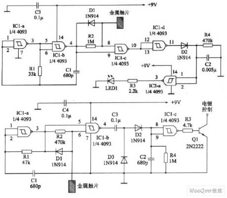
The circuit shown in the figure only uses a touch metal chip,the circuit uses two forty-two input terminals(internal has four identical, with two input terminals) schmitt trigger 4093(such as CD4093,TC4093 etc.).Usually the output terminal's 3 pin of IC2-a is low,light-emitting diode LED1 can not shine,when touching metal chip, the output terminal changes into high level to make the LED1 turn and light.
(View)
View full Circuit Diagram | Comments | Reading(2163)
Undervoltage,overvoltage protection alarm circuit
Published:2011/7/9 2:07:00 Author:Fiona | Keyword: undervoltage,overvoltage protection, alarm
Work principle
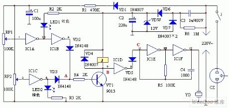
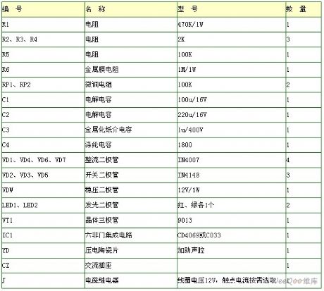
Circuit is shown as above.Mains voltage reduces voltage by C3,maintains voltage by DW,VD6,VD7,C2 rectifier filter output maintaining DC voltage supply circuit.Another path is rectified by VD1,reduced voltage by R1 and filtered by C1, the voltage about 12V produced in RP1、RP2 detects the input signal of the mains voltage change.Door IC1A,IC1B form the overvoltage detection circuit, IC1C is undervoltage detection,IC1D is switch,IC1E,IC1F,piezoelectric ceramicchip YD and other components form the audio pulse oscillator. Transistor VT,relay J and other components form the protection movement circuit.Red LED1 is for mains overvoltage indication,the green LED2 is for mains voltage undervoltage indication.
(View)
View full Circuit Diagram | Comments | Reading(3599)
W1840 control circuit, main features and pin of DC-DC circuit and power supply monitor
Published:2011/7/10 2:32:00 Author:Lucas | Keyword: control circuit, main features , pin , DC-DC circuit , power supply monitor
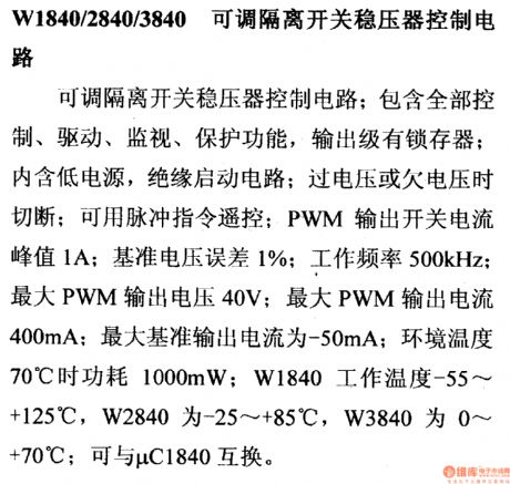
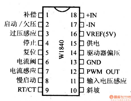
W1840/2840/3840 adjustable isolated switching regulator control circuit
It is the isolated switching regulator control circuit; it contains the functions of all the control, drive, monitor, protection, output stage latch; it contains low power, insulation start circuit; it cuts off when over voltage or under voltage; it is available in pulse command remote control; PWM Output switching current peak is 1A; reference voltage error is 1%; frequency is 500KHz; maximum PWM output voltage is 40V; maximum PWM output current is 400mA; maximum reference output current is -50mA; when ambient temperature is 70 ℃, the power is 1000mW; W1840 operating temperature is -55 ~ +125 ℃, W2840 is -25 ~ +85 ℃, W3840 is 0 ~ 70 ℃, and it is interchangeable with μC1840.
(View)
View full Circuit Diagram | Comments | Reading(517)
Sound Control Twinkling Illuminations(3)
Published:2011/7/10 7:57:00 Author:Sue | Keyword: Sound Control, Twinkling, Illuminations
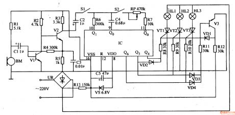
The 220v ac voltagewill provide the sound control circuit and IC with 6.8v direct current working voltage after it is rectificated by UR, limited and reduced by R13, stablized by VS, filtrated by C5.
S2,R6,R7,RP,C4 and IC's pin 9-11's inner circuits will compose oscillator circuit which will provide IC with count pulse. IC's Q4-Q6 terminals will output control voltage signals which will make VT1-VT3 connected by R8-R10,VD1-VD4,V3 in turn, or it will make two thyristors connected at the same time(or make 3 thyristors connected at the same time). HL1-HL3 will be illuminated in turn or two groups of illuminations will be illuminated at the same time(or 3 groups of illuminations will be illuminated at the same time). (View)
View full Circuit Diagram | Comments | Reading(620)
Twinkling Ornamental Illuminations (2)
Published:2011/7/9 1:48:00 Author:Sue | Keyword: Twinkling, Ornamental, Illuminations
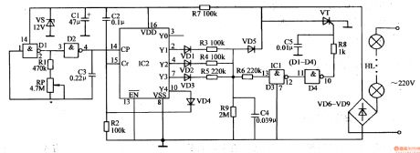
When IC2's Y1-Y3 terminals output high level(when one terminal outputs high level, other terminals will output low level), C4 will be charged. Its voltage will be put on VT's gate electrode through R6,NOT GATE D3,D4 and R8 which will make VT connected. HL will be illuminated. After VT is connected, C4 will charge VT through VD5. Because the resistance values of the resistor R3,R4,R5 are different from each other, when IC2's Y1-Y3 terminals output high level respectively, C4's charge time is different, which will make VT's conductingextents different. Then HL's working voltages are different which will make the illuminations brightness different. The smaller the resistor(R3-R5)'s resistance values are, the longer C4's charge time will be, the larger VT's conducting angle will be, the higher HL's working voltage will be, and the lighter the illuminations will be.
(View)
View full Circuit Diagram | Comments | Reading(594)
Twinkling Ornamental Illuminations (1)
Published:2011/7/10 7:59:00 Author:Sue | Keyword: Twinkling, Ornamental, Illuminations

The 220v ac voltage will provide IC with 12v direct current working voltage after it is rectificated by VD1, limited by R3, stablized by VS, filtrated by C2.
After the multivibrator begins to work, D1's,D2's output terminals will output high level and low level alternately, which will make VT1,VT2 connected and disconnected alternately. Then HL1,HL2 are illuminated alternately(When VT1 is connected, the first circuit of illuminations HL1 are illuminated; When VT2 is connected, the second circuit of illuminations HL2 are illuminated).
By adjusting RP1's and RP2's resistance values and C1's capacity, the multivibrator's oscillate period and frequency can be adjusted. Then the twinkle frequency of HL1,HL2 can be changed. (View)
View full Circuit Diagram | Comments | Reading(535)
Automatic Sprinkling Irrigation Controller (4)
Published:2011/7/10 7:24:00 Author:Sue | Keyword: Automatic, Sprinkling Irrigation, Controller
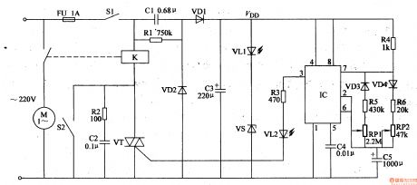
When the switch S1 is on, the 220v ac voltage will generate VDD(12.5-13V) voltage after it is reduced by C1, rectificated by VD1,VD2, filtrated by C3, stablized by VS. The voltage will provide IC with working voltage. After the power circuit begins to work, the LED VL1 is illuminated.
After the power circuit begins to work, besides providing IC with working voltage, VDD voltage also charge the capacitor C5 through resistor R4, diode VD4, resistor R6, potentiometer RP2, capacitor C5. At first IC's pin 6 has low level, IC's pin 3 outputs high level which will make VL2 illuminated and VT connected. The relay K is connected. The electric motor M begins to work and begin to spray. (View)
View full Circuit Diagram | Comments | Reading(483)
LED Festival Illumination Controller (4)
Published:2011/7/8 7:05:00 Author:Sue | Keyword: LED, Illumination, Controller
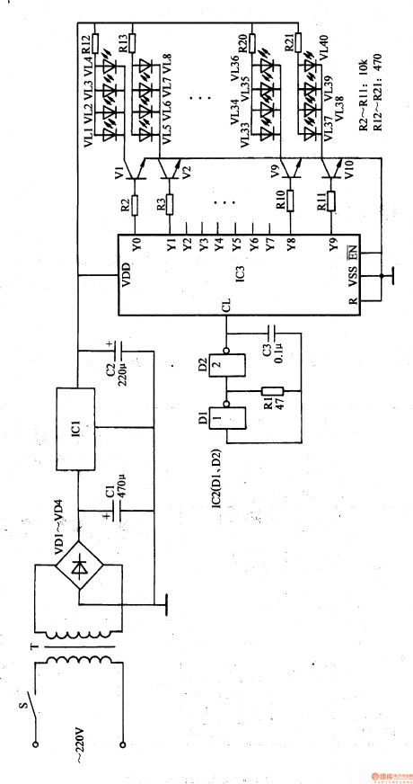
After the autoexciting oscillator begins to work, it will provide IC3 with count pulse. Under the effect of the count pulse, its Y0-Y9 terminals will output high level in turn which will make V1-V10 connected in turn. These LEDs will be drived to be illuminated in turn.
After IC3 is reset, its Y0 terminal will output high level which will make V1 connected. VL1-VM will be illuminated. When its Y1 terminal outputs high level, V2 is connected. VL5-VL8 are illuminated(Y0 terminal return to low level; V1 is disconnected and VL1-VM are off)......When Y8 terminal outputs high level, V9 is connected. VL33-VL36 are illuminated. When Y9 terminal outputs high level, V10 is connected. VL32-VL40 are illuminated. Then different illumination effects can be generated. (View)
View full Circuit Diagram | Comments | Reading(536)
LED Festival Illumination Controller (3)
Published:2011/7/10 8:10:00 Author:Sue | Keyword: LED, Illumination, Controller
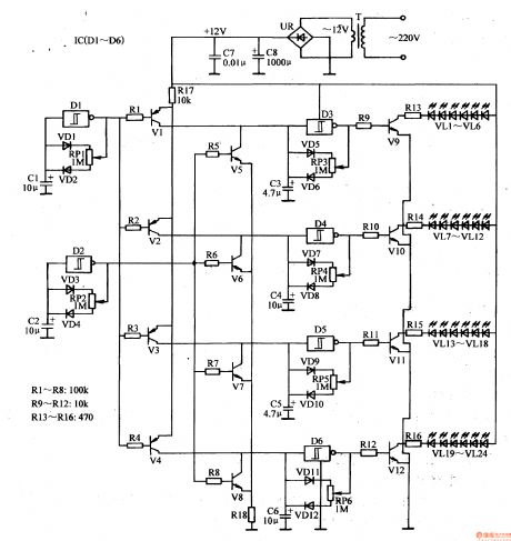
The 220v ac voltage will provide the square wave oscillator, control circuit, drive output circuit with +12v direct current voltage after it is reduced by T, rectificated by UR, filtrated by C7,C8.
The square wave pulse output by D1 will control D3-D6 by V1-V4. The square wave signals output by D2 will control D3-D6 by V5-V8.
When D1 outputs low level, V1-V4 are connected. D3-D6 will stop oscillating because its input terminals are forced to have high level. D3-D6 output low level. Vg-V12 are disconnected at the same time. VL1-VL14 are off at the same time. Then D1 outputs high level which will make V1-V4 disconnected. Square wave oscillator composed of D3-D6 will begin to work. V9-V12 are connected intermittently under the control of square wave pulse. VL1-VL24 are illuminated. (View)
View full Circuit Diagram | Comments | Reading(647)
LED Festival Illumination Controller (2)
Published:2011/7/10 8:08:00 Author:Sue | Keyword: LED, Illumination, Controller
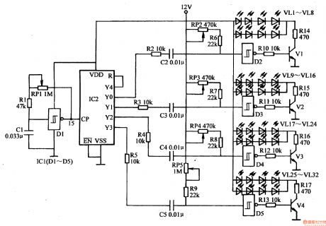
The LED drive circuit consists of IC1's inner trigger D2-D5, resistor R6-R7, transistor V1-V4, potentiometer RP2-RP5 and LED VL1-VL32.
When the power is on, the clock pulse generator circuit begins to oscillate. The trigger D1's output terminal will output clock pulse signals with a frequency of 6Hz. The signals will be put on IC2's CP terminal(pin 15) which will serve as the counter's count pulse. After IC2 counts and allocates the clock pulse signals, its Y0-Y4 terminals will output high level in turn which will promote the circuit to work. (View)
View full Circuit Diagram | Comments | Reading(1298)
LED Festival Illumination Controller (1)
Published:2011/7/10 8:05:00 Author:Sue | Keyword: LED, Illumination, Controller
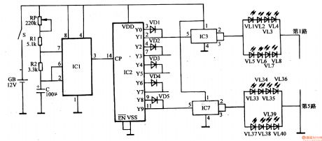
The autoexciting oscillator circuit consists of base integrated circuit IC1, resistor R1,R2, capacitor C and potentiometer RP.
The count freqency divider consists of count/pulse distributor integrated circuit IC2 and diode VD1-VD5.
The electronic switch circuit consists of electronic switch integrated circuit IC3-IC7.
When the power switch S is connected, the autoexciting oscillator begins to work. IC1's pin 3 will output low frequency square wave pulse which will be put on IC2's CP trigger count terminal(pin 14). Then IC begins to count, and its Y0-Y9 terminals will output high level in turn which will make the electronic switch integrated circuit IC3 and IC7 connected in turn. Its output terminals(pin 2 and pin 3)' outside LED will be illuminated. (View)
View full Circuit Diagram | Comments | Reading(633)
Sound Control Twinkling Illuminations (2)
Published:2011/7/8 7:47:00 Author:Sue | Keyword: Sound Control, Twinkling, Illuminations
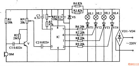
The 220v ac voltage will provide the sound control circuit and IC with +12v working voltage after it is rectificated by VD1-VM, limited and reduced by R4,R5, stablized by VS, filtrated by C4.
After IC begins to work, its pin 1, pin 2, pin 6, pin 7 will output 4 circuits of control signals which will make VT1-VW connected in turn. Then illuminations HL1-HL4 will be drived to be illuminated and generate a running flowing illumination effect. BM will turn the musical signals it receives into electric signals, which will be put on IC's pin5 through C2 after it is amplified by V, volume adjusted by RP1. The signals can adjust the oscillate frequency of IC's inner voltage control oscillator which will make the illumination effects change with the musical signal's rhythm synchronically. (View)
View full Circuit Diagram | Comments | Reading(553)
Sound Control Twinkling Illuminations (1)
Published:2011/7/8 7:35:00 Author:Sue | Keyword: Sound Control, Twinkling, Illuminations
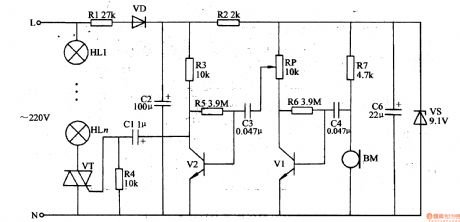
The 220v ac voltage will provide V1 and V2 with +9v working voltage after it is reduced by R1, rectificated by VD, filtrated by π formfilter(consists of C2,R2 and C6), stablized by VS.
BM will transform the audio signals it receives into electric signals, then through C4, the signals will be put to the amplifier which is composed of V1,V2 and the signals will be amplified.The amplified audio signals will be put on VT's gate electrode(G elecrode) through C1 which will control the connection and disconnection states of VT as well as theconduction angle. When there is no sound, VT is disconnected and illuminations HL1-HLn are not illuminated. The louder the sound is, the larger VT'sconduction angle is and the lighter the illuminations are. (View)
View full Circuit Diagram | Comments | Reading(486)
Automatic Sprinkling Irrigation Controller (3)
Published:2011/7/10 7:10:00 Author:Sue | Keyword: Automatic, Sprinkling Irrigation, Controller
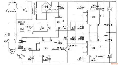
After the knife switch Q is on, if S2 is put on 1 (manual), the ac contactor KM will be connected. Its normally open contact will be connected and the electric motor will begin to work. If S2 is put on 2 (automatic), then only when the relay K1 or its normally open contact is connected that KM can be connected and M can begin to work.
In the automatic condition(when S2 is put on 2 ), when the power switch S1 is on, the 220v ac voltage will provide IC1-IC3 with +12v working voltage after it is reduced by T, rectificated by VD1-VD4, filtrated by C1, stablized by IC1. (View)
View full Circuit Diagram | Comments | Reading(650)
Automobile Fuel Supply Indicator
Published:2011/7/10 7:32:00 Author:Sue | Keyword: Automobile, Fuel Supply, Indicator
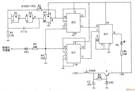
The automobile's storage battery's +12v voltage will output +5v voltage from V's emitting electrode after it is filtrated by L,C2, adjusted by V, stablized by VS2. The voltage will provide the pulse oscillator, counter, LED indicator circuit with working voltage.
The detecting pulse which is output by the oil pressure sensor will be put on IC2's pin 3 and IC3's pin 14 through the level converter. When the input detecting pulse signal has low level, R4's voltage is lower than 0.4 v. When the input pulse signal has high level, R4's voltage reaches 2.7V.
After the pulse oscillator begins to work, it will provide IC2 with count pulse signal with a frequency of 500Hz. (View)
View full Circuit Diagram | Comments | Reading(629)
Motorcycle Deceleration Indicator
Published:2011/7/10 5:34:00 Author:Sue | Keyword: Motorcycle, Deceleration, Indicator

When the motorcycle has a constant speed, the deceleration automatic switch S1 is disconnected and IC's pin Z and pin 4 both have high level. HL is not illuminated. When the motorcycle is slowing down, according to the mechanics principle, the motorcycle will have a negative acceleration, which will make S1's inner moving contact have a forward driving force. Then the moving contact and the fixed contact will be connected and IC's pin Z and pin 4 will have low level and HL is illuminated.
C is the time-delay capacitor. When S1's moving contact and fixed contact are disconnected, C is charged through R2. When C's voltage reaches 1.6v, IC's pin 4 becomes high level. Then the occasion that the brake lamp HL will not twinkle when the motorcycle is running on an uneven road will be avoided. (View)
View full Circuit Diagram | Comments | Reading(701)
Motorcycle Gears Indicator (2)
Published:2011/7/10 6:08:00 Author:Sue | Keyword: Motorcycle, Gears, Indicator
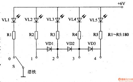
VL1 is neutral LED indicator. VL2-VL5 are gear 1-4 LED indicators respectively.
+V terminal is connected with the motorcycle's neutral LED's power.
When the switch is on, it is in neutral. Only the neutral LED indicator VL1 is illuminated. VL2-VL5 are not illuminated.
When the motorcycle is in gear 1, S's moving contact and 1 terminal are connected together. VL2 is illuminated while VL1 is off.
When the motorcycle is in gear 2, S's moving contact and 2 terminal are connected together. VD1 is connected. VL2 and VL3 are both illuminated.
When the motorcycle is in gear 3, S's moving contact and 3 terminal are connected together. VD1,VD2 are both connected. VL2-VL4 are all illuminated.
When the motorcycle is in gear 4, S's moving contact and 4 terminal are connected together. VD1-VD3 are all connected. VL2-VL5 are all illuminated. (View)
View full Circuit Diagram | Comments | Reading(1656)
Motorcycle Gears Indicator (1)
Published:2011/7/10 5:55:00 Author:Sue | Keyword: Motorcycle, Gears, Indicator
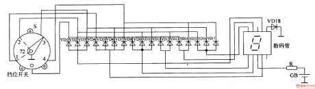
The storage battery GB's 12v(or 6v) voltage will be put on the digitalindicator after it is limited by R.
When the motorcycle is in neutral gear, S's moving contact and neutral contact are connected together, which will make the diode VD1,VD5,VD8,VD11,VD13 connected. The digital indicator indicates number 0 .
When the motorcycle is in gear 1, S's moving contact and gear 1 contact are connected together, which will make the diode VD4 connected. The digital indicator indicates number 1 .
When the motorcycle is in gear 2, S's moving contact and gear 2 contact are connected together, which will make the diode VD2,VD9,VD12,VD15 connected. The digital indicator indicates number 2 .
When the motorcycle is in gear 3, S's moving contact and gear 3 contact are connected together, which will make the diode VD3,VD6,VD10,VD16 connected. The digital indicator indicates number 3 .
When the motorcycle is in gear 4, S's moving contact and gear 4 contact are connected together, which will make the diode VD7,VD14,VD17 connected. The digital indicator indicates number 4 . (View)
View full Circuit Diagram | Comments | Reading(2562)
Motorcycle Speed Indicator (3)
Published:2011/7/9 6:31:00 Author:Sue | Keyword: Motorcycle, Speed Indicator
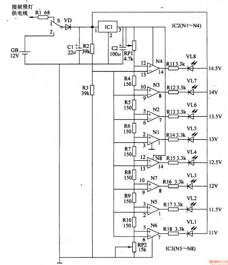
The voltage which is generated by alternator will be put on LED VL1-VL8's positive electrode which will serve as display working power after it is limited by R1, rectificated by VD, filtrated by C1. One circuit will provide the operational amplifier N1-N8's inverting input terminals with sampling voltage after it is voltage divided by R2,R3. The other circuit will provide IC2,IC3 with working voltage after it is stablized by IC1. The +9v voltage also provide N1-N8's voltage input terminals with base voltage after it is voltage divided by RP1,R4-R10,RP2.
The motorcycle's speedis proportionate tothe alternator's speed of rotation, that is when the motorcycle runs fast, the alternator's output voltage is high, and there will be many VL1-VL8's illuminated LEDs. When the device is used, the driver can adjusting the speed by monitoring the numbers and extent of the illuminations, so the safety can be ensured. (View)
View full Circuit Diagram | Comments | Reading(907)
| Pages:208/312 At 20201202203204205206207208209210211212213214215216217218219220Under 20 |
Circuit Categories
power supply circuit
Amplifier Circuit
Basic Circuit
LED and Light Circuit
Sensor Circuit
Signal Processing
Electrical Equipment Circuit
Control Circuit
Remote Control Circuit
A/D-D/A Converter Circuit
Audio Circuit
Measuring and Test Circuit
Communication Circuit
Computer-Related Circuit
555 Circuit
Automotive Circuit
Repairing Circuit