
Index 209
Motorcycle Speed Indicator (2)
Published:2011/7/9 6:10:00 Author:Sue | Keyword: Motorcycle, Speed Indicator

The motorcycle alternator(speed detection alternator)'s output voltage will serve as V1's and V2's bias voltage after it is voltage divided by R1,RP. The voltage will control the working states of V1,V2. The faster the motorcycle is running, the higher the alternator's output voltage will be, the higher the bias voltage will be, the stronger V1's and V2's conducting ability will be, the more illuminated lights of VL1-VL6 will be.
When the motorcycle begins to run, VL1-VL6 are all illuminated and V3-V9 are all connected. IC obtains working voltage which can drive HA to make an alarm sound to warn the driver that The motorcycle has exceeds the speed limit. Please slow down .
By adjusting RP's resistance value, VL1 will be illuminated when the speed is 10km/h. When the speed is 60km/h, the illuminations are all illuminated. When the speed exceeds 70km/h, there will be an alarm. (View)
View full Circuit Diagram | Comments | Reading(596)
Motorcycle Speed Indicator (1)
Published:2011/7/9 5:41:00 Author:Sue | Keyword: Motorcycle, Speed Indicator
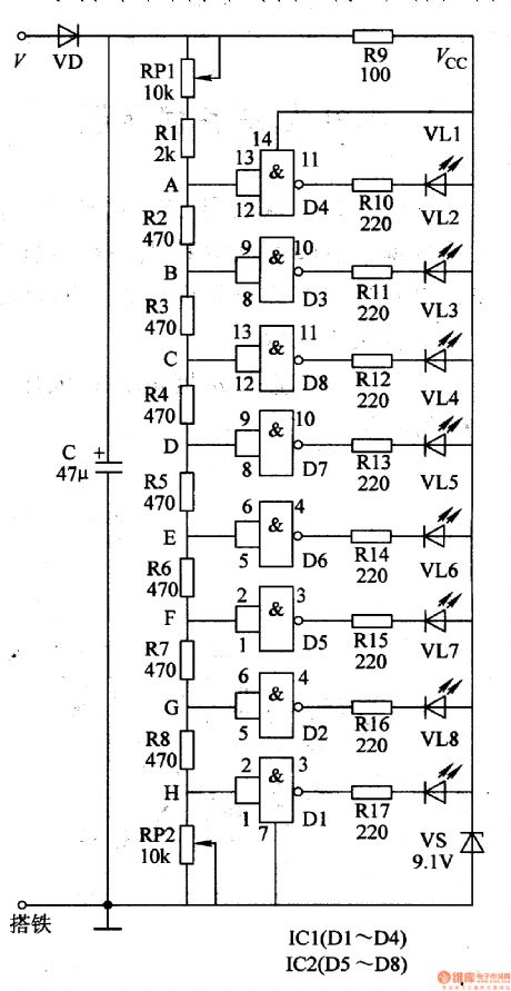
The alternator's output voltage V(It is achieved from ac voltage output from the alternator's head lamp's supply winding) will be divided into two circuits after it is rectificated by VD, filtrated by C. One circuit will provide IC2,IC1 and VL1-VL8 with 9v voltage after it is limited by R9, stablized by VS. The other circuit will generate 8 different detect voltage on A-H terminals after it is voltage divided by the voltage division circuit. When one terminal's detect voltage reaches NOT GATE circuit's threshold level, the NOT GATE circuit will output low level, which will make its output terminals outside circuit's diodes illuminated. The motorcycle rider can get to know the current motorcycle speed by the number and standard of illuminated diodes. (View)
View full Circuit Diagram | Comments | Reading(617)
LED Festival Illumination Controller (5)
Published:2011/7/10 7:43:00 Author:Sue | Keyword: LED, Illumination, Controller
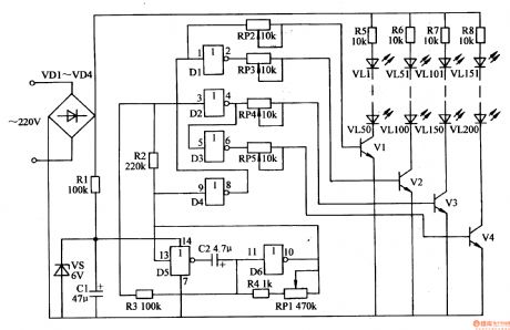
The 220v ac voltage will provide LED drive circuit with working voltage after it is rectificated by VD1-VD4. The other circuit will provide IC with +6v working voltage after it is limited and reduced by R1, stablized by VS, filtrated by C1.
After the oscillator begins to work, it will output low frequency oscillate signals. The signals will be put on V1-V4's base electrode through RP2-RP5 after it is reversal processed by D1-D4. Then V1-V4 are connected intermittently. VL1-VL50, VL51-VL100, VL101-VL150,VL151-VL200 will be illuminated intermittently.
By adjusting RP1's resistance value,the oscillator'sworking frequency will be changed. Then LED's illumination effects can be changed. (View)
View full Circuit Diagram | Comments | Reading(694)
Stepper Motor ULN2003 Internal Diagram And Equivalent Circuit
Published:2011/7/8 23:31:00 Author:Robert | Keyword: Stepper Motor, Internal, Diagram, Equivalent

In practice general driving channels is more than one. But using the discrete circuit shown in the picture will get large volume. So in many cases it always uses ready-made ICs for multi-channel driving. Commonly used small type stepper motor driving circuit can be ULN2003 or ULN2803. This book's auxiliary experiment board uses the ULN2003. ULN2003 is one of the high-voltage large-current darlinton transistor array series products. It features high current gain, high working voltage, wide temperature range, high loading capacity and so on. So it is adequate to many kinds of high-speed large-power driving systems. The ULN2003A is made up of 7 groups darlinton transistor arrays and corresponding resistances network and clamping diodes network. It has the load capacity of driving 7 groups at the same time. It is a single-chip bipolar large-power high-speed IC. The ULN2003 internal structure and its equivalent circuit is shown in the picture. (View)
View full Circuit Diagram | Comments | Reading(3132)
Switching power supply circuit with low-noise RCC mode
Published:2011/7/9 4:31:00 Author:chopper | Keyword: Switching, power supply, low-noise, RCC mode

Figure shows the grid drive circuit which uses the saturable reactor,switching power supply with low-noise RCC mode.Its output is 24V/4.5A, and it is as example of soft switching applications.
(View)
View full Circuit Diagram | Comments | Reading(3752)
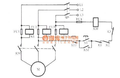
Starting insurance for starting injection and running out circuit
Published:2011/7/5 10:32:00 Author:John
Three-phase motor’s starting current is large, which is generally three times more of the motor’s rated current. If the chosen fuse (also known as fuse) is with a larger rated current, it is rater detrimental to the protection for the motor. The phenomenon of frequent burning of insurance frequently occurs even if it is in the right size. The circuit as shown can be used to resolve this contradiction. As for the figure, FU1 is the motor main fuse with the right size and FU2 is a launching insurance. Rated current of FU1 should be equal to the motor’s rated current. And rated current of FU2 is generally equals to that of the FU1.
(View)
View full Circuit Diagram | Comments | Reading(835)
Exhaust fan automatically starting circuit
Published:2011/7/5 8:56:00 Author:John | Keyword: Exhaust fan
The circuit is as shown. 220-volt power supply is divided into two routes. One route is transferred into a 5V power supply through the transformer, aiming to supply the control circuit. The other route is connected to the exhaust fan through the relay in series. As for control circuit, the 5-volt power supply gets DC power supply through the rectifier. Commonly, R3, the partial pressure of R3 can not be the transistor due to a smaller resistance. So the relay is not energized and the exhaust fan does not work. When the heater is heated, heat resistance of R3 becomes larger. And the partial pressure on the R3 would induct the transistor. Then the relay pulls and exhaust fan works. (View)
View full Circuit Diagram | Comments | Reading(1633)
three contactors for consisting Y-△ buck starting circuit
Published:2011/7/10 3:09:00 Author:Lucas | Keyword: contactor
View full Circuit Diagram | Comments | Reading(737)
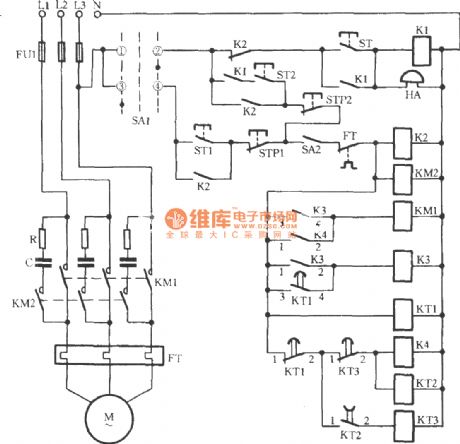
Three-phase motor dual-speed 2Y / △ connection with indicator regulator circuit
Published:2011/7/10 2:46:00 Author:Lucas | Keyword: Three-phase motor, indicator
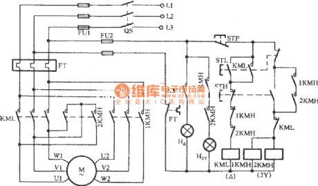
The circuit increases the low speed indicator H △ and high-speed indicator H2Y. When the motor stops, the two lights are not lighted.
(View)
View full Circuit Diagram | Comments | Reading(8271)
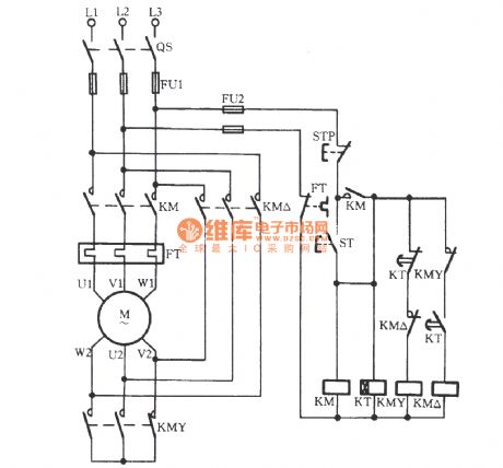
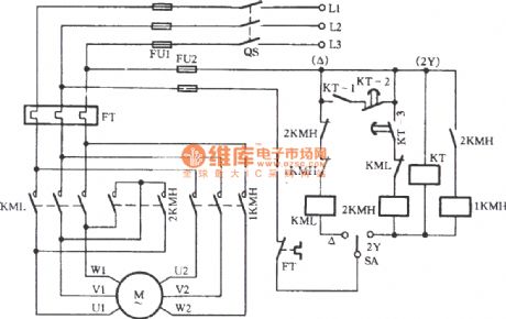
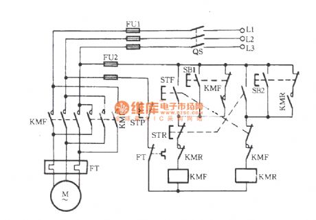
Three-phase motor dual-speed 2Y / △ connection speed control circuit (a)
Published:2011/7/10 2:54:00 Author:Lucas | Keyword: 2KMH, Three-phase motor, 2Y / △ connection
There are three AC contactors used in the circuit. The button STH is the high-speed control button. When it is pressed, AC contactor 1KMH and 2KMH suctions at the same time, thus driving the motor M for high-speed (2Y) operation. The button STL is the low-speed control button. When it is pressed, AC contactor KML suctions to drive the motor M for low-speed (△) operation. When the button STP is pressed, the motor stops running. FT is a thermal relay for overload protection.
(View)
View full Circuit Diagram | Comments | Reading(12095)
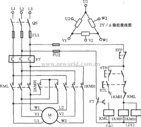
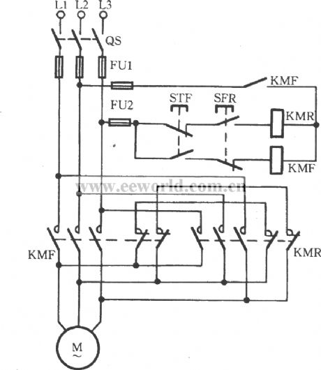
Three-phase motor dual-speed 2Y / △ connection automatic speed control circuit
Published:2011/7/10 2:56:00 Author:Lucas | Keyword: Three-phase motor, 2Y / △ connection
View full Circuit Diagram | Comments | Reading(4475)
△-shaped three-phase motor buck starting circuit
Published:2011/7/10 3:07:00 Author:Lucas | Keyword: three-phase motor

The start button ST is pressed to drive the 1KM coil to gain electricity and to be self-protected. At the same time, 3KM relay coil KT gains electricity and motor’s windings are connected to form a extending triangle for buck starting. When the Kt's tuning time reaches, the delaying normally closed contacts disconnect. Then the 3KM coil releases with the loss of power and its normally closed auxiliary contact is closed. Meanwhile, KT’s delaying closing normally opened contacts are closed. The 2KM coil gains electricity to suction and to be self-locked. 3KM’s main contact releases while 2KM’s main contact closes. Then the motor windings are transferred from extending triangle shape into a triangle connection. The starting process is over and the operation is on.
(View)
View full Circuit Diagram | Comments | Reading(2036)
Fuse voltage control signal relay open-phase protection circuit
Published:2011/7/10 Author:Lucas | Keyword: Fuse voltage , control signal, relay , open-phase protection
View full Circuit Diagram | Comments | Reading(1096)
Three-phase motor for extend the △ access to single-phase operation circuit
Published:2011/7/9 9:34:00 Author:Lucas | Keyword: Three-phase motor
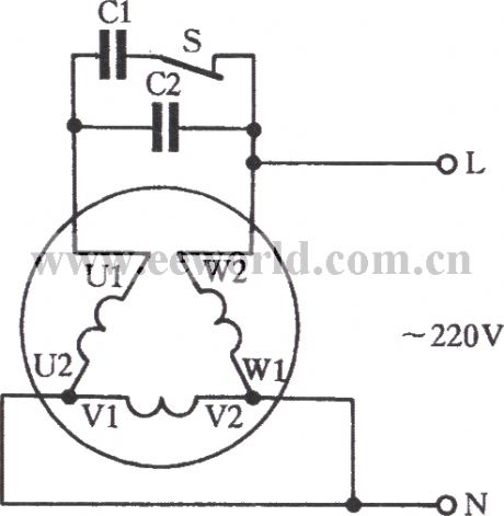
Extension three-phase motor with △-connection is suitable for 220V or 380V single-phase power operation. The circuit is shown below. The principle of this connection is the same to that of Y-connection, but there are some differences either. (1) It can be seen from the figure that only one U phase-phase winding is the main winding among the motor windings. And the V phase and W phase are connected in series as auxiliary windings. (2) Winding U and winding V, W form an autotransformer. Due to the boosting function of the autotransformer, capacitors C1 and C2 are exposed to bear voltage which is three times of that of the single-phase power supply. As a result, a capacitor with a high working voltage is needed to be used, such as a capacitor of 1000V.
(View)
View full Circuit Diagram | Comments | Reading(2339)
three-phase motor with 36V low-voltage control circuit
Published:2011/7/10 2:36:00 Author:Lucas | Keyword: three-phase motor
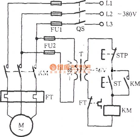
Just as shown in the circuit, the motor is a full-voltage direct starting circuit. And its control circuit’s power supply is the AC voltage reduced by the transformer T from 380V to 36V. Therefore, the AC contactor’s coil voltage must be 36V. In wet or such situations, the security has been ensured.
(View)
View full Circuit Diagram | Comments | Reading(3369)
reversible controlling point of the three-phase motor short brake circuit
Published:2011/7/9 9:47:00 Author:Lucas | Keyword: three-phase motor
The circuit is shown. When STR is pressed, the reverse contactor KMR pulls to disconnect the braking short contacts (KMR’s normally closed contacts), thus driving the motor to run reversely. When STR is released, the contactor releases with the loss of power. And the main contact KMR is off. At this time, braking short contacts restore the closed state to drive the stator coil to produces the M braking torque for braking. Similarly, forward braking operation is done with the same methods and principles as described above. This brake circuit is only applies for small motors below 3kW.
(View)
View full Circuit Diagram | Comments | Reading(2157)
Three-phase motor contactor button interlock action for switching circuit
Published:2011/7/9 10:48:00 Author:Lucas | Keyword: Three-phase motor, contactor button, interlock
Just shown in the figure, STF, STR, SB1 and SB2 all are composite buttons. STF and STR are respectively positive and reverse button, which operate along with the contactor’s auxiliary contacts for achieve interlock action. SB1 and SB2 both are jog buttons. (View)
View full Circuit Diagram | Comments | Reading(3559)
Three-phase motor intermittent starting circuit
Published:2011/7/10 2:29:00 Author:Lucas | Keyword: Three-phase motor
View full Circuit Diagram | Comments | Reading(1158)
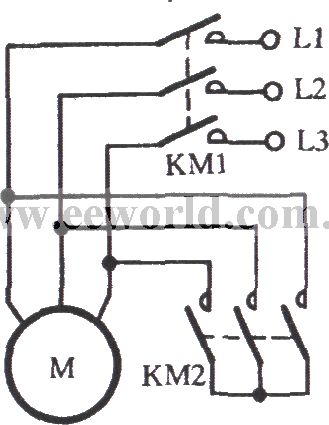
Three-phase motor self-motivation brake circuit
Published:2011/7/10 2:22:00 Author:Lucas | Keyword: Three-phase motor, KM2
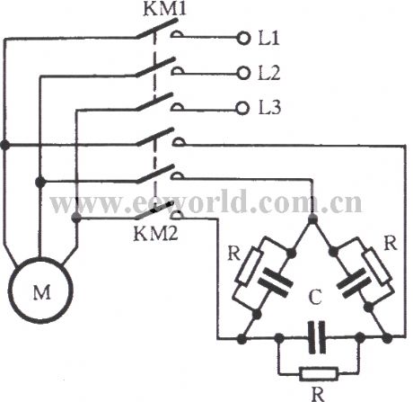
Just as shown in the figure, RC components are connected to stator windings during the free braking so as to form a self-motivation brake circuit. 2KM is closed when the KM1 is off. At this moment, the stator’s remanence induction would generate a capacitive current by RC circuit. It will strengthen the rotor’s remanence magnetic created by its magnetic. The brake torque is formed for braking the motor at high speed. RC circuit’s connection should be done according to the winding connection of the three-phase stator. It is tested that RC with Y connection circuit is suitable for Y-connection motor.
(View)
View full Circuit Diagram | Comments | Reading(2928)
Simple three-phase motor short braking circuit
Published:2011/7/10 0:25:00 Author:Lucas | Keyword: three-phase motor, KM1
The stator windings maintain the opening state at this moment. The EMF does not produce current and dose not produce braking torque. Thus it is called free brake. If the stator winding is disconnected from the grid as shown in the figure and is short connection by KM2, the remanence potential of the stator windings can be generated to produce current. And the resulting braking effect is called short brake”. When the 5.5kW motor short-circuit brakes, short-circuit current is with duration of 100 milliseconds. It is better than free braking, whose braking time is 3 / 4 of the free braking time.
(View)
View full Circuit Diagram | Comments | Reading(1630)
| Pages:209/312 At 20201202203204205206207208209210211212213214215216217218219220Under 20 |
Circuit Categories
power supply circuit
Amplifier Circuit
Basic Circuit
LED and Light Circuit
Sensor Circuit
Signal Processing
Electrical Equipment Circuit
Control Circuit
Remote Control Circuit
A/D-D/A Converter Circuit
Audio Circuit
Measuring and Test Circuit
Communication Circuit
Computer-Related Circuit
555 Circuit
Automotive Circuit
Repairing Circuit