
Index 207
laser transmitter linearity controlling circuit diagram
Published:2011/6/18 21:22:00 Author:Lena | Keyword: laser transmitter, linearity controlling
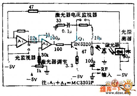
Using optics feedback technology can keep invariable laser output inawide temperature change range.This circuit is a optics negative feedback that is not sensentive to temperture range.
(View)
View full Circuit Diagram | Comments | Reading(575)
Light-Operated Streetlight (10)
Published:2011/7/8 5:41:00 Author:Sue | Keyword: Light-Operated, Streetlight
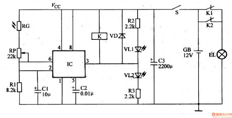
In the daytime, the photeresistor RG will have a low resistance value because of the light. IC's pin 2's and pin 6's voltages arehigher than 2Vcc/3. IC's pin 3 will output low level, which will make the relay K connected. Its normally open contactors K1 and K2 are both disconnected and the illumination EL is not illuminated.
When it is dark, RG will have a larger resistance value because of lack of light. IC's pin 2's and pin 6's voltages will become lower. When the voltage is lower than Vcc/3, IC's pin 3's low level will become high level which will make the relay K released. Its normally closed contactors K1 ,K2 are both connected. The illumination EL is illuminated. (View)
View full Circuit Diagram | Comments | Reading(523)
Light-Operated Streetlight (1)
Published:2011/7/8 5:35:00 Author:Sue | Keyword: Light-Operated, Streetlight
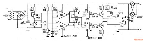
The 220v ac voltage will provide the light-operated circuit and trigger control circuit's IC1,IC2,K with +gV working voltage after it is reduced by T, rectificated by UR, filtrated by C1. The +9v voltage is also divided into four circuits. One will serve as electric supply detect sampling voltage after it is voltage divided by R2,RP2. One will provide N1's positivephaseinput terminal with light-operated signal voltage after it is voltage divided by R1,RP1,RG. One will provide N1's negative phase input terminal and N2's positive phase input terminal with 4V base voltage after it is voltage divided by R3,VS. Another one will provide V1 with working voltage after it is limited by R6.
In the daytime, RG has a low resistance value because of the light. N1's positive phase input terminal(IC1's pin 5)'s voltage is lower than that of negative phase input terminal(IC1's pin 4)'s, so it outputs low level.AND NOT GATE D1,D3 both output high level. D2,D4 both output low level.V1,V2 are disconnected. K is not connected and VT1,VT2 are disconnected. EL1-ELn are not illuminated. (View)
View full Circuit Diagram | Comments | Reading(522)
Light-Operated Streetlight (2)
Published:2011/7/8 5:51:00 Author:Sue | Keyword: Light-Operated Streetlight
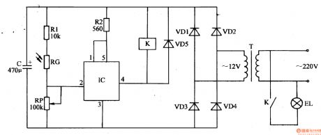
The 220V ac voltage will provide the light-operated circuit with +12V working power after it is reduced by T, rectificated by VD1-VD4, filtrated by C.
In the daytime, RG will have a low resistance value because of the light, which will make IC's pin2 and pin 4(output terminal) output high level. Its inner electronic switch is disconnected and K is disconnected. The illumination EL is not illuminated.
In the evening, RG will have a high resistance value because of lack of light, which will make IC's pin 2 output low level. Its inner electronic switch is connected and EL is illuminated.
By adjusting RP's resistance value, the light-operated sensitivity will be changed. (View)
View full Circuit Diagram | Comments | Reading(518)
Light-Operated Streetlight (3)
Published:2011/7/8 5:19:00 Author:Sue | Keyword: Light-Operated, Streetlight
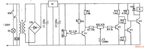
The 220V voltage will provide the light-operated circuit with +12V voltage after it is reduced by T, rectificated by UR, filtrated by C1, stablized by IC.
In the daytime, RG will have a low resistance value because of the light. V1,V3 are connected. v2,v4 are disconnected. K,KM don't work and the streetlight is not illuminated.
In the evening, RG will have a high resistance value and V1,V3 are disconnected. V2 and V4 are connected. K, KM will be connected. The streetlight is illuminated.
By adjusting potentiometer RP1's resistance value, the illuminations can be on and off in the proper light. (View)
View full Circuit Diagram | Comments | Reading(517)
Light-Operated Streetlight (4)
Published:2011/7/8 6:03:00 Author:Sue | Keyword: Light-Operated, Streetlight
In the daytime, the photoresistor RG will have a low resistance value because of the light. IC's pin 2 and pin 6 will output high level(higher than 2Vcc/3). Its pin 3 will output low level. VL is not illuminated and VT is disconnected. The illumination EL is not illuminated.
In the evening, RG's resistance value will be higher because of the light is becoming less. IC's pin 2 and pin 6 will have a lower voltage. When IC's pin 2's voltage is lower than Vcc/3, IC's inner trigger will be reversed. Its pin 3 outputs high level. VL is illuminated. VT is connected and the illumination power is on. EL is illuminated. (View)
View full Circuit Diagram | Comments | Reading(437)
Light-Operated Streetlight (5)
Published:2011/7/8 6:00:00 Author:Sue | Keyword: Light-Operated, Streetlight
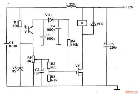
The light-operated circuit consists of light-operated transistor V, diodes VD1,VD2, capacitor C2-C4, field effect transistor VF, potentiometer RP, resistor R2-R4 and relay K.
In the daytime, V has a low resistance value because of the light and V is disconnected. VF is connected. K is connected. The working power is cut off by its normally closed contactor and the streetlight is not illuminated. In the evening, V has a high resistance value and VF is disconnected. K is released. The working power is connected by its normally closed contactor, then the streetlight will be illuminated.
By adjusting RP's resistance value, the light-operated sensitivity can be changed. (View)
View full Circuit Diagram | Comments | Reading(625)
Light-Operated Streetlight (6)
Published:2011/7/8 5:53:00 Author:Sue | Keyword: Light-Operated, Streetlight
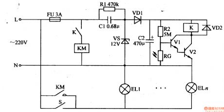
The light-operated circuit consists of photoresistor RG, resistor R2, transistors V1,V2, relay K, ac contactor KM, diode VD2 and manual switch S.
The 220v ac voltage will provide the light-operated circuit with 12v working voltage after it is reduced by C1, stablized by VS, rectificated by VD1, filtrated by C2.
In the daytime, RG will have a low resistance value which will make V1,V2 disconnected. K, KM are released. K and KM are disconnected. EL1-ELn are not illuminated.
When it is dark, RG will have a higher resistance value which will make V1,V2 connected. K is connected and its normally open switch is connected. KM is connected and EL1-ELn are illuminated. (View)
View full Circuit Diagram | Comments | Reading(592)
Light-Operated Streetlight (7)
Published:2011/7/8 5:47:00 Author:Sue | Keyword: Light-Operated, Streetlight
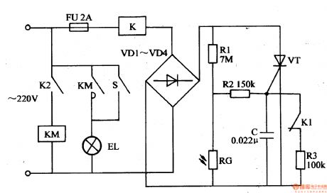
The 220v ac voltage will become direct current voltageafter it is reduced by K, rectificated by VD1-VD4. One circuit will be put on VT's positive electrode. The other circuit will provide VT's gate electrode with trigger voltage through R2 after it is voltage divided by R1,RG.
In the daytime, RG will have a low resistance value because of the light. C's voltage is low, so VT is not connected. K and KM are not connected. Illuminations EL1-ELn are not illuminated.
When it is dark, RG has a high resistance value which will make C have a higher voltage. VT will be connected and K is connected. Its normally closed contactor K1 is disconnected, while its normally open contactor K2 is connected. KM is connected. KM's normally open contactor will make EL1-ELn's working power connected. EL1-ELn will be illuminated. (View)
View full Circuit Diagram | Comments | Reading(523)
Light-Operated Streetlight (13)
Published:2011/7/5 23:37:00 Author:Sue | Keyword: Light-Operated, Streetlight
In the evening, RG has a high resistance value because of lack of light. A's electric potential becomes higher and higher. IC1's pin 6's voltage is higher than 2Vcc/3. Its pin 3 outputs low level. VD1,VD3 and V are disconnected and VD2 is connected. B will have high level and IC2's pin 6's voltage is higher than 2Vcc/3 too. IC2's pin 3 outputs low level which will make VT connected. EL is illuminated. At the same time, C3 is discharged slowly through R6,R7 and RP2. Then IC2's pin 2's voltage becomes lower and lower. Time delay is about 4.5-6.5h. When IC2's pin2's voltage is lower than Vcc/3, its pin 3 outputs high level again which makes VT disconnected and EL is off. (View)
View full Circuit Diagram | Comments | Reading(383)
Fluorescent Lamp Electronic Ballast (5)
Published:2011/7/7 5:08:00 Author:Sue | Keyword: Fluorescent Lamp, Electronic, Ballast
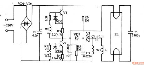
When the power is on, the 220v ac voltage will provide the high frequency oscillate circuit with 300v direct current working voltage afterit is rectificated by VD1-VD4, filtrated by C1. C3 is charged by R6 and when C3's voltage reaches V3's breakover voltage, VS will be connected quickly. C3 begins to be discharged on T's winding W3 through V3. Then V1 and V2 will be connected intermittently under the coupling of T. The high frequency oscillator will begin to work.After the oscillator begins to work, C2 will generate a high frequent alternating voltage which is similar to sine wave and the voltage will be provided to EL through C4,L1. When C5's voltage reaches EL's discharging voltage, EL will be illuminated. (View)
View full Circuit Diagram | Comments | Reading(7954)
Over-voltage protection circuit uses the two-way trigger diode to trigger the two-way thyristor
Published:2011/7/8 5:50:00 Author:Christina | Keyword: Over-voltage, protection, two-way, trigger diode, two-way thyristor
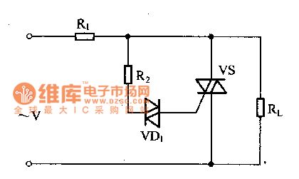
The over-voltage protection circuit which is composed of the two-way trigger diode and the two-way thyristor is as shown in figure 1. When the voltage is normal, the voltage of the two-way trigger diode is smaller than the turning voltage, the VD1 will not conduct, the two-way thyristor is in the cut-off state, the load RL can get the power. When the power supply transient voltage is the over voltage, the voltage which is added on the two-way trigger diode is larger than the tuning voltage, so VD1 conducts and triggers the two-way thyristor to conduct it, so the load RL is away from the overvoltage damage.
Figure 1 The over-voltage protection circuit
(View)
View full Circuit Diagram | Comments | Reading(1512)
absolute value amplifier with polarity detector circuit
Published:2011/6/12 21:36:00 Author:chopper | Keyword: absolute value amplifier, polarity detector
View full Circuit Diagram | Comments | Reading(578)
Auto Flash Alarm
Published:2011/7/10 23:50:00 Author:Felicity | Keyword: Auto Flash, Alarm
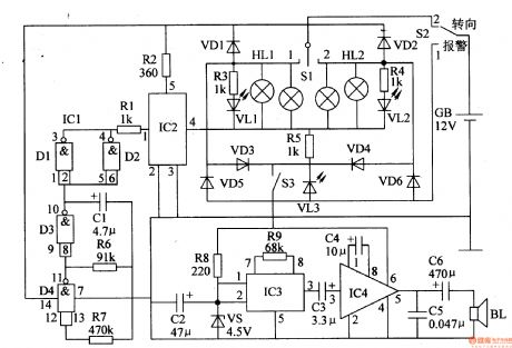
Work of the circuit
The circuit consists of low-frequency oscillator, the electronic switch circuit, control circuit, photoelectric display circuit and music alarm circuit. (It is showed in picture 7-113.)
Low-frequency oscillator consists of IC lCl (Dl-D4) internal NAND gate circuit D3, D4 and external RC components.
Control circuit consists of ICl internal non-gate Dl and D2. It is used to control high-power electronic switch IC lC2.
Photoelectric display circuit consists of diode VDl-VD6, LED VLl-VL3 (installed in the steering switch) and the resistors R3-R5.
Music alarm circuit consists of music integrated circuit IC3, audio amplifier integrated circuit IC4, speaker BL and related peripheral components. (View)
View full Circuit Diagram | Comments | Reading(1662)
Relay circuit directly drived by the analog switch chip
Published:2011/7/8 5:55:00 Author:TaoXi | Keyword: Relay circuit, analog switch chip
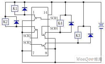
The CD4066 is designed as one kind of quad two-way analog switch, the integrated blocks SCR1~SCR4 are the control ports. When the SCR1 is connected with the high level, the pin-1 and pin-2 of the integrated block conduct, the +12V voltage adds to the K1 to connect the pin-1 and pin-2 with the negative electrode of the power supply, so K1 closes; otherwise when the SCR1 is connected with the low level, the pin-1 and pin-2 of the integrated block are the open circuits, K1 releases, the states of the SCR2~SCR4 are the same as the state of the SCR1 when SCR2~SCR4 are connected with the high or low level.
In this circuit, both ends of the relay coil are connected with the diode to protect the integrated circuit itself.
(View)
View full Circuit Diagram | Comments | Reading(704)
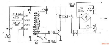
Intermittent Controller (the 1st)
Published:2011/7/10 22:42:00 Author:Felicity | Keyword: Intermittent Controller,

Work of the circuit
The circuit consists of power circuit, timer and control implementation circuit. (It is showed in picture 8-96.)
Power circuit consists of Capacitors C2-C4, resistors R3-R5, bridge rectifier, UR, voltage regulator diode VS and power indicator LED VL.
Timer circuit consists of counter / divider integrated circuit IC, capacitor Cl, diode VD2-VD4 and resistors Rl, R2, R6. Clock oscillator circuit consists of Rl、R2、Cland IC internal circuit.
Control implementation circuit consists of transistor V, resistor R7, diode VDl, relay K and AC contactor KM. (View)
View full Circuit Diagram | Comments | Reading(802)
Intermittent Controller (the 2nd)
Published:2011/7/10 22:43:00 Author:Felicity | Keyword: Intermittent Controller,
Work of the circuit
The circuit consists of power circuit, timing control circuit and control implementation circuit. (It is showed in picture 8-97.)
Power circuit consists of fuse FU, power transformer T, bridge rectifier, UR, filter capacitor C3, three-terminal voltage regulator integrated circuit IC2, current limiting resistor Rl and the power indicator LED VLl.
Timing control circuit consists of time-base integrated circuit ICl, potentiometer RPl and R Robinson, resistor R2, work instructions LED VL2 and capacitors Cl, C2.
Control implementation circuit consists of relay K, AC contactor KM and diode VD. (View)
View full Circuit Diagram | Comments | Reading(871)
Intermittent Controller (the 3rd)
Published:2011/7/10 22:45:00 Author:Felicity | Keyword: Intermittent Controller,
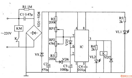
Work of the circuit
The circuit consists of power circuit, timing control circuit and control implementation circuit. (It is showed in picture 8-98.)
Power circuit consists of Buck capacitor Cl, resistors Rl, R5, rectifier diode VDl-VD4, voltage regulator diode VS, power indicator light-emitting diode VL1and filter capacitor C2.
Timing control circuit consists of time-base integrated circuit IC, resistors R2-R4, capacitors C3, C4, potentiometer RPl, RP2, diode VD5, VD6 and light-emitting diode VL2.
Control implementation circuit consists of diode VD7, relay K and AC contactor KM. (View)
View full Circuit Diagram | Comments | Reading(831)
Voltage Regulator (the 4th)
Published:2011/7/3 5:06:00 Author:Felicity | Keyword: Voltage Regulator (the 4th)
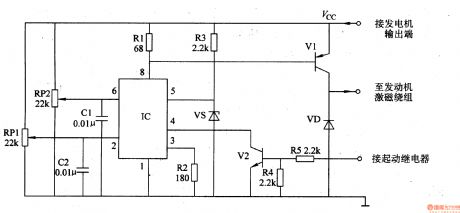
Work of the circuit
The circuit consists of time-based integrated circuit IC, potentiometer RP1, Rm, capacitor C1, C2, resistor R1-R5, stabilizing diode VS, diode VD and transistor V1 and V2. (It is showed in picture 7-144.)
Turn on the power switch of the mobile and the motor is starting. Here V2 is transmitted. When the motor works, V2 is cut-off. The exporting voltage of the AC motor is adjusted by R3 and VS. Then it supplies 6V reference voltage to pin5 of IC. When the exporting voltage is less than 14.4 V, the exporting voltage on the motor is increasing. When the exporting voltage reaches 14.9V, the exporting voltage is decreasing. The process repeats to keep the exporting voltage in the range of 14.4-14.9V.
RP1 is used to set the least voltage.
RP2 is used to set the highest voltage. (View)
View full Circuit Diagram | Comments | Reading(704)
Voltage Regulator (the 5th)
Published:2011/7/3 5:07:00 Author:Felicity | Keyword: Voltage Regulator (the 5th)
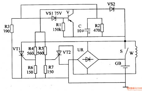
Work of the circuit
The circuit consists of time-based integrated circuit IC, potentiometer RP1, Rm, capacitor C1, C2, resistor R1-R5, stabilizing diode VS, diode VD and transistor V1 and V2. (It is showed in picture 7-144.)
When the motor van is working, the exporting voltage of W is rectified by UR. It then charges the battery TB and supplies power to the electrical equipment such as the light on the car. When the speed of the motor is low, the charging voltage on GB is lower than 14.5V. The exporting voltage is rectified by UR and then charges GB. When the speed of motor is high, the charging voltage on the GB is increasing. When the voltage is larger than 14.8V, the exporting current is shunted. In this way the charging voltage is stabilized to the value of 14.8V. (View)
View full Circuit Diagram | Comments | Reading(667)
| Pages:207/312 At 20201202203204205206207208209210211212213214215216217218219220Under 20 |
Circuit Categories
power supply circuit
Amplifier Circuit
Basic Circuit
LED and Light Circuit
Sensor Circuit
Signal Processing
Electrical Equipment Circuit
Control Circuit
Remote Control Circuit
A/D-D/A Converter Circuit
Audio Circuit
Measuring and Test Circuit
Communication Circuit
Computer-Related Circuit
555 Circuit
Automotive Circuit
Repairing Circuit