
Index 205
two motors for sequential starting circuit
Published:2011/7/10 20:19:00 Author:John | Keyword: motor, sequential starting
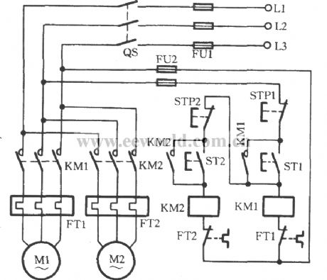
Some production machines have two or more electric motors, because these motor play different roles in the circuit. Sometimes, a certain sequence must be conformed to start in order, thus ensuring the normal production. The used circuit is shown in the figure. Take the two electric motors M1 and M2 used here for example. When the ST1 is pressed, KM1 coil is energized. And the coil’s main contacts and auxiliary contacts take action. And the motor M1 launches to be self-locked. It is obvious that KM1’s closure contact would not be self-locked if the ST2 is pressed firstly rather than the motor M1 (that is the ST1). Beside, KM2 coil would be in power shortage and be not able to start the motor M2.
(View)
View full Circuit Diagram | Comments | Reading(13727)
4-quadrant multiplication analog multiplication arithmetic circuit
Published:2011/7/8 3:20:00 Author:Fiona | Keyword: 4-quadrant multiplication, analog multiplication

Circuit function
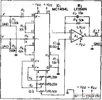
MC1494L is a monolithic analog multiplication IC composed of double-balanced differential amplifier, voltage - current converter circuit,a the general multiplication circuit which can use an external device to set the working conditions. It is capable of 4-quadrant multiplication and it is suitable of the various circuit which the input voltage is the positive and negative 10V.
Circuit work
In order to scale factor of 10, the resistances of resistors R5, R6 take 30K and 62K, lead terminal 14 is the collector output type.Owing to the current output,it adds the OP amplifier A1 to convert between current and voltage.The bias of IC1 output becomes the A1's positive input.
(View)
View full Circuit Diagram | Comments | Reading(1042)
two electric motors for sequential parking circuit
Published:2011/7/10 20:19:00 Author:John | Keyword: electric motor, sequential parking
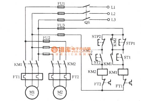
In some working procedures, it is required to part the first motor and followed to park another motor. The figure shows the circuit of adapting to run the program. When the starting button ST1 is pressed, motor M1 operates. Then, the ST2 is pressed to pull KM2, leading to the operation of motor M2. Due to the KM2's pull, its normally opening contact is self-locked and the other contact closes to short the stop button STP1. Therefore, if the STP1 is pressed by mistake, KM1 will not lose power and release it. And the motor M1 will not stop at this time. Only the STP2 is pressed firstly to stop the motor M2 can the KM2 lose power. Then, its normally opening contacts release. Only under this situation can it is possible to stop M1 by pressing STP1.
(View)
View full Circuit Diagram | Comments | Reading(2342)
High Q Band-pass Filter Circuit
Published:2011/7/9 10:56:00 Author:Joyce | Keyword: High Q , Band-pass , Filter
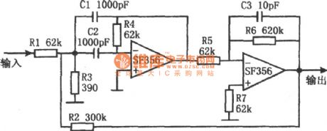
As shown in the figure is a high Q bandpass filter circuit. This circuit uses two operational amplifiers SF356 with high input impedance, of which the first stage working as a common single-section filter, whose Q value is low, the value of R3 is smaller, attenuation value is larger, and the magnification factor is small. But the magnification factor of the second stage inverse proportional amplifier is 10 times .And it will reach the input end of the first grade through R2 to introduce a certain amount of positive feedback, thus improving the Q value of the whole circuit. Therefore the filter has good frequency-selecting feature. (View)
View full Circuit Diagram | Comments | Reading(1922)
Simple and practical touch delay switch circuit
Published:2011/6/13 21:38:00 Author:Fiona | Keyword: Simple and practical, touch delay switch
Delay switch circuit is shown in Figure D1 - D1, SCR component switch is composed of main circuit, BG1, BG2 switch and other components switches are composed of the control circuit. Switching delay time is mainly determined by the value of the resistance R1, R2 and capacitor C1. Provide a group of experimental data below for reference.If it want to further increase delay time, it can increase the capacity of C1. In addition to these major factors, BG1 magnification and the trigger sensitivity of the SCRare also affected to delay time. (View)
View full Circuit Diagram | Comments | Reading(1009)
Water towers water level controller circuit
Published:2011/7/8 3:23:00 Author:Fiona | Keyword: level controller
IC2 can use a variety of 555 time base integrated circuits. IC3 is the infrared receiver decoder CX20106A. IC4 can use 4N25, 4N26, PC817 and other optocoupler. Part of the infrared receiver can purchase finished infrared receiver components or integrated infrared receiver,it’s easy to produce and improve reliability. VD1, VD2 and VD3 can use infrared transmitter and receiver diodes of TVremote control. J chooses to use a new selection of memory self-locking relay,the shape of this relay is same as the general replay, the difference is that the pullis not required to maintain current,justwhen pulling and releasingit requires a certain pulse drive power, then the mechanical structure maintains locked state.
(View)
View full Circuit Diagram | Comments | Reading(1898)
water level automatic control circuit consisting of 555
Published:2011/7/8 2:28:00 Author:Fiona | Keyword: water level automatic control
As shown in figure is water level automatic control circuit. The control circuit is composed of step-down rectifier circuit,water level measurement and control switch,flip and flop generator and so on.Step-down rectifier circuit provides VDD = 12 V power supply voltage for 555.Two steady state work patterns of 555 is used as RS trigger. BG1 and upper limit water level probe A are reset trigger switch; BG2 and the median probe B are setting trigger switch; C is the lower limit probe connecting to the ground electrical level. Using the characteristics of RS trigger and controlling the setting and resetting of 555 make the relay J absorb or release , so as to control the operation of the pumping motor D to make water level keep in the given upper limit and lower limit.
(View)
View full Circuit Diagram | Comments | Reading(1880)
TWH8778 radio automatic shutdown circuit
Published:2011/7/7 7:09:00 Author:Fiona | Keyword: radio automatic shutdown, sound signal
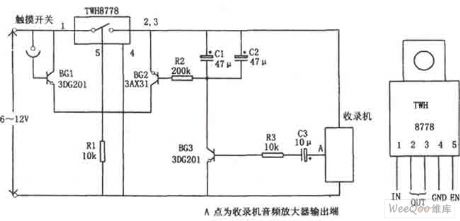
The circuit mainly uses a new type of power switching device TWH8778.It produces simply and has no debugging.TWH8778 shape and the function of the pins is shown as above,the ⑤ pin is control side,when the pin's voltage is higher than the cut-in voltage (about 1.6V), the electronic switch is closed, ①, ② pins are connected. When touching the contact of the touch switch between BG1 and the power,BG1 is conducted,the voltage drop of R1 makes TWH8778 close,the recorder works normally due to the power is connected.If the recorder is on playback, thesound signal is coupled by C3 to the base of BG3 to make BG2 conduct,BG2 has a base current and it is in the conduction state,the voltage drop of R1 makes TWH8778 close again. (View)
View full Circuit Diagram | Comments | Reading(909)
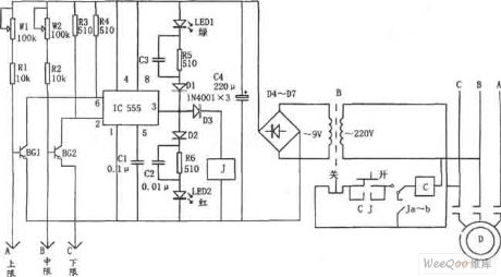
A bean sprouts automatic watering controller consisting of 555 circuit
Published:2011/7/8 2:20:00 Author:Fiona | Keyword: automatic watering controller
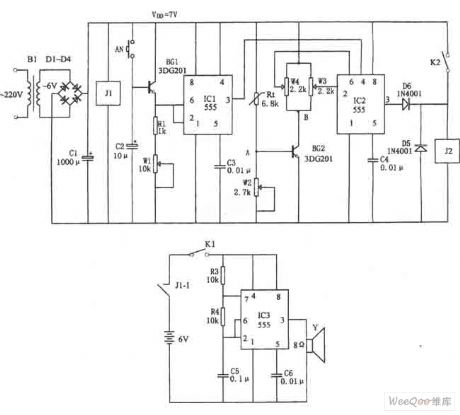
Figure shows the bean sprouts automatic watering control circuit. The controller consists of step-down rectifier circuit, power outage told implement (IC3), timing control circuit (IC1), temperature control circuit(IC2) and so on. The step-down rectifier circuit is VDD = +7 V DC voltage provided by the whole controller. The power outage told implement is controlled by many harmonic oscillator which consists of IC3,R3,R4,C5 and other components. Close the switch K1, when the power cuts, the relay J1 releases, contact J1-1 closes, IC3 starts oscillation due to get electricity, the oscillation frequency is about 1000Hz, the output signal drives the speaker sound to inform the owner that the power goes out. (View)
View full Circuit Diagram | Comments | Reading(1284)
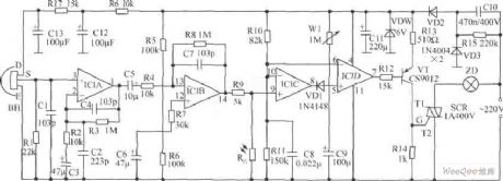
the wind speed program control circuit consisting of 555
Published:2011/7/8 2:25:00 Author:Fiona | Keyword: the wind speed program control
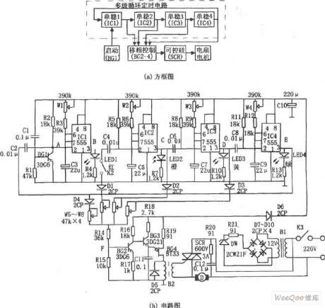
Just when turning on the power,the start-up circuit consisting of R1,C1 and BG1 produces a negative pulse and adds to the trigger of IC1 (555) (② pin), so that the delay circuit consisting of IC1, W1, R3, C3 is set and outputs the high level. The corresponding delay time is td1 = 1.1 (Rw1 + R3) C3, the parameters of the corresponding time is about 0.6 to 10 seconds. During this time, C3 is charged, when the voltage of C3 is filling to make the ⑥ pin reach 2/3VDD, IC1 is reset,after low level output by 3-pin differentials through the C4, R5,it adds to ② pin of IC2 to make the corresponding timing circuit is set and outputs high levelbecause that the ② pin is low level. IC3, IC4's change of state is similar.
(View)
View full Circuit Diagram | Comments | Reading(607)
a TV set automatic shutdown control circuit consisting of 555
Published:2011/7/8 2:18:00 Author:Fiona | Keyword: automatic shutdown control
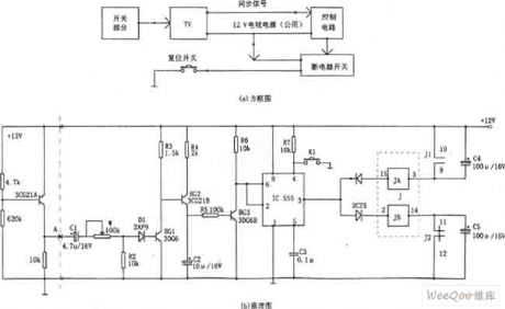
When there is a television program,the sync signal from point A makes BG1 saturated conduct,BG2, BG3 conducts, so that 555 is set due to thepin ② is low level, the high level output by ③ feet makes JB put together, J1 is closed and the TV power supply connects up; when the television program is aired, synchronous signal disappears, BG1, BG2 end.C2 which has been charged discharges through the emitter of R5, BG3 and makesBG3 stay about 10 minutes conducting timeto avoid the undue off phenomenon caused by intermittent or replacement when program broadcasts. (View)
View full Circuit Diagram | Comments | Reading(731)
consisting of 555 no tower pressurization supply water liquid level control circuit
Published:2011/7/8 2:33:00 Author:Fiona | Keyword: no tower pressurization, supply water, liquid level control
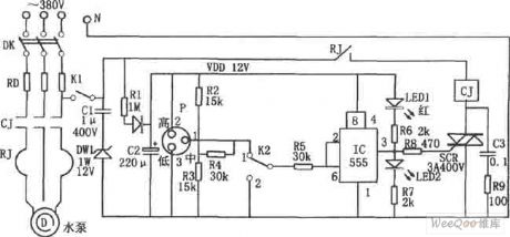
The control circuit consists of capacitance step-down rectifier circuit,electro connecting pressure gauge,555 trigger circuit,SCR control circuit. Capacitance step-down rectifier circuit provides DC voltage for the whole control circuit.When there is no water in the water control, the electro connecting pressure gauge P's internal pressure is low,the movable contact l in table and lower contact 3 are closed,so that IC (555) ② pin is low level,the corresponding 555 is set,the high level output by 3-pin makes the semiconductor control rectifier SCR trigger conduct,CJ pulls in, pump D fetches water inside the water control,the pressure in the pressure gauge increases. (View)
View full Circuit Diagram | Comments | Reading(1095)
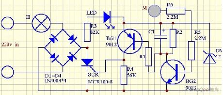
Timed trigger switch circuit
Published:2011/7/1 5:51:00 Author:Fiona | Keyword: timed, trigger switch
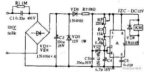
The AC power source reduces the voltage by the capacitance C1,bridge rectifies by diode vDl—vD4,filters by the capacitor C2 and obtains the 12V DC voltage in both ends of the diode VD5.After rectifying and current-limiting by the diode vD6 and resistor R2,the supply voltage charges the capacitor c4 by potentiometer RP, and resistors R3, R4.When the voltage of the A's ② ⑥ pins is greater than 2 / 3 supply voltage because of c4 both ends voltage being charged to time base integrated circuit, A is in reset state, its ③ pin is low,the relay KM is closed to make the moving contacts are launched to control the trigger circuit or lanterns.
(View)
View full Circuit Diagram | Comments | Reading(767)
The switching solenoid driver circuit
Published:2011/7/8 3:18:00 Author:Fiona | Keyword: switching solenoid

The picture shows the switching solenoid driver circuit,the device U8 is 74123 chip, the device 02,03 are solid-state relays,coil PUSH is the switching inhaled coil,HOLD's ability is to maintain the coil,the power supply VDD is 24V.When the switching mechanism converts to dual fuel conversion mechanism working condition,Y1 input from 74123's B pin jumps from low to high.This change will make 74123's the output end Q input a transient high current pulse,the maintain time is ΔT.After the inverter 7404,the potential UA of A-point will appear the same width of pulse low level,the input of solid-state relay 02 has ΔT time current passed,when the output of the solid-state relay 02 has ΔT time conduction.
(View)
View full Circuit Diagram | Comments | Reading(1932)
The fire damper auto control circuit of the air-conditioner
Published:2011/7/7 1:10:00 Author:Borg | Keyword: fire damper, control circuit, the air-conditioner
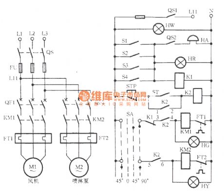
In the project that there is the requirement of ventilation and air-conditioning, there must be the fire damper in the air supply and return tube. When there's a fire, the temperature of air supply or return is rising up (about 70oC), which fuses the fuse strip of the fire damper, the damper is closed and makes the micro switch take action, so the fire alarm is ringing, the wind motor stops, see as the figure. This system has 4 fire dampers. When SA is in 90o (left 45o is pump running, right 45o is the motor running, 0 is shutting down), just press the key of starting ST. (View)
View full Circuit Diagram | Comments | Reading(2510)
Large power switch-The important tasks of transistors
Published:2011/7/7 1:08:00 Author:Borg | Keyword: power switch, transistors
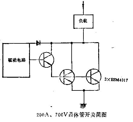
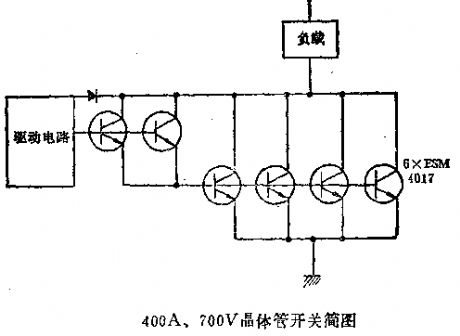
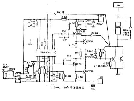
1. Controlling the large power Nowadays, the power transistor can control powers of hundreds of thousands of volt, using the transistor as the switch has many virtues, which are:(1) it's easy to cut off, and it needs a few additional elements; (2) it's fast to switch, and it can work in a high frequency; (3) the withstand voltages of the available elements range from 100V to 700V. Years ago, the switching ability of the transistor is lower than 10kW. Nowadays, it can control powers of hundreds of thousands of volt.2. It directly works on the transistor power switch of the rectified 380V mains
(View)
View full Circuit Diagram | Comments | Reading(701)
UCC3895N phase shift control circuit
Published:2011/7/8 21:08:00 Author:chopper | Keyword: phase shift, control circuit
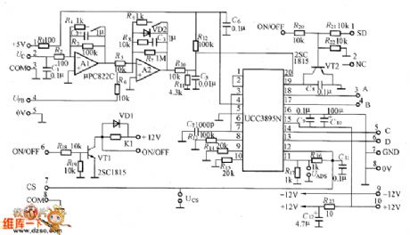
Figure shows the UCC3895N phase shift control circuit,and in order to reduce the interference of the power switching circuit, it can substrate the control circuit.Uc control input voltage of ② end of left placode can offer 0~+5V voltage by connecting 5V benchmark voltage of UCC3895N to 10kΩ adjustable resistor,can also use D/A converter to generate the control voltage. It can not join capacitor Ca in order to speed up response time. (View)
View full Circuit Diagram | Comments | Reading(1585)
traditional PWM control full-bridge circuit
Published:2011/7/9 3:12:00 Author:chopper | Keyword: traditional, PWM control, full-bridge circuit
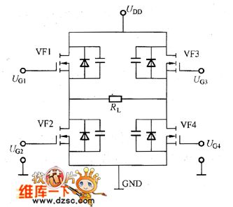
Figure shows a traditional PWM control full-bridge circuit and waveforms of control signal. As for 4 switches in the circuit,VF1 and VF4 will conduct meanwhile(positive output), and VF2 and VF3 will conduct meanwhile(negative output). Change the conduction and close time of switch tube as well as duty ration to control the output voltage.
(View)
View full Circuit Diagram | Comments | Reading(744)
NE555 Overvoltage and Overcurrent Protection Circuit
Published:2011/6/23 10:10:00 Author:Michel | Keyword: Overvoltage, Overcurrent, Protection Circuit
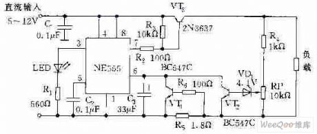
The picture is the overvoltage and overcurrent protection circuit composed of NE555. VT1 and VT ends, NE555 resets, and all of the transistor is in conduction mode.It absorbs current from VT3 which makes VT stay in saturation condition and 5~12V DC power supply provides load via VT3.When load current exceeds rating value and voltage on RS increases which makes VT1 conduct and NE555 be triggered and then VT3 stops,load power supply cuts off.At the time,NE555 is in monostable condition and NE555 is triggered again VT3 continuely isolates load from power supply as long as the load flow does not rule out. (View)
View full Circuit Diagram | Comments | Reading(3021)
6-way infrared remoter controller circuit without no debugging
Published:2011/7/9 10:09:00 Author:Lena | Keyword: 6-way, infrared, remoter controller, no debugging
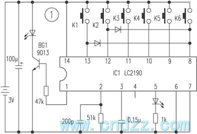
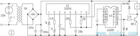
Here introduces a remote controller that consists of transmitting and receiving parts.Transmitting circuit is with LC2190 as the core, K1-K6 are coding switchs, C2 is a pulse interval timing capacitance. Modulated coding signal is outputted by IC1 ① pin, then be amplified by BG1, and be emitted by load infrared LED. The principle is shown figure 1.Receiving circuit is shown in figure 2. Encoding signal transmitted by remote controller is sent to LC2200 by IC2 CX20106, then LC2200 outputs control various ways load, A-F are related K1-K6 control output ends.
(View)
View full Circuit Diagram | Comments | Reading(988)
| Pages:205/312 At 20201202203204205206207208209210211212213214215216217218219220Under 20 |
Circuit Categories
power supply circuit
Amplifier Circuit
Basic Circuit
LED and Light Circuit
Sensor Circuit
Signal Processing
Electrical Equipment Circuit
Control Circuit
Remote Control Circuit
A/D-D/A Converter Circuit
Audio Circuit
Measuring and Test Circuit
Communication Circuit
Computer-Related Circuit
555 Circuit
Automotive Circuit
Repairing Circuit